Contents
• Design Considerationsfor horizontal and vertical
vessels
• Foundation for rotating equipment
• Equipment loads and loading combinations
• Checks required during design
• Foundation types for static equipment.
3.
1. Design Procedure:
1.1Dead Loads: If you apply working strength design or limit state
design, the dead load will consist of the following items (these loads
represent all the types that will affect the pressure vessel during its
lifetime
1. Structure dead load (Ds): the weight of the foundation and soil above
the part of the foundation that resists uplift.
2. Erection dead load (Df): the fabricated weight of the exchanger or
vessel, generally taken from certified exchanger or vessel drawings.
3. Empty dead load (De): the empty weight of the exchanger or vessel,
including all attachments, trays, internals, bundle, insulation, fireproofing,
agitators, piping, ladders, platforms, and others. The eccentric load should
also be added to the empty dead load weight.
4. Operating dead load (Do): the load affect during operation. This load
will be the empty dead load of the exchanger or vessel, in addition to the
maximum weight of contents during normal operation. The eccentric load
should also be added to the operating dead load weight.
5. Test dead load (Dt): the load during testing of the vessel. This load is
the dead load of an empty vessel plus the weight of the test medium
contained in the system. The fluid that will be used in the test should be as
specified in the contract documents or by the owner.
4.
1.2 Live Loads
•The live load data is concerned with access for maintenance of valves, measurement, and other activities.
There will be less load effect in these cases than in the case of pressure vessels.
1.3 Wind Loads
• The engineering office is responsible for determining the wind loads (W) used for the foundation design.
Wind loads from vendors or other engineering disciplines should not be accepted without verification.
• Transverse wind—the wind pressure on the projected area of the side of the exchanger or vessel—should
be applied as a horizontal shear at the center of the exchanger or vessel. Including the wind load on
projections such as piping, manways, insulation, and platforms during wind analysis is important.
• Longitudinal wind—the wind pressure on the end of the exchanger or vessel—should be applied as a
horizontal shear at the center of the exchanger or vessel. The flat surface wind pressure on the exposed area
of both piers and both columns should also be included, applied as a horizontal shear at the centroid of the
exposed area.
5.
1.4 Earthquake Loads
•The procedures and limitations for the design of structures shall
be determined by considering seismic zoning, site
characteristics, occupancy, configuration, structural system, and
height.
• Earthquake loads (E) should be calculated in accordance with
the relevant code of the country where the plant is located, but
in general, UBC is the most popular code for earthquake loads
for buildings, whereas SEI/ASCE 7-05 is preferred for
nonbuilding structures, as this code focuses specifically on
them.
• In India, we use IS-1893 Part I
6.
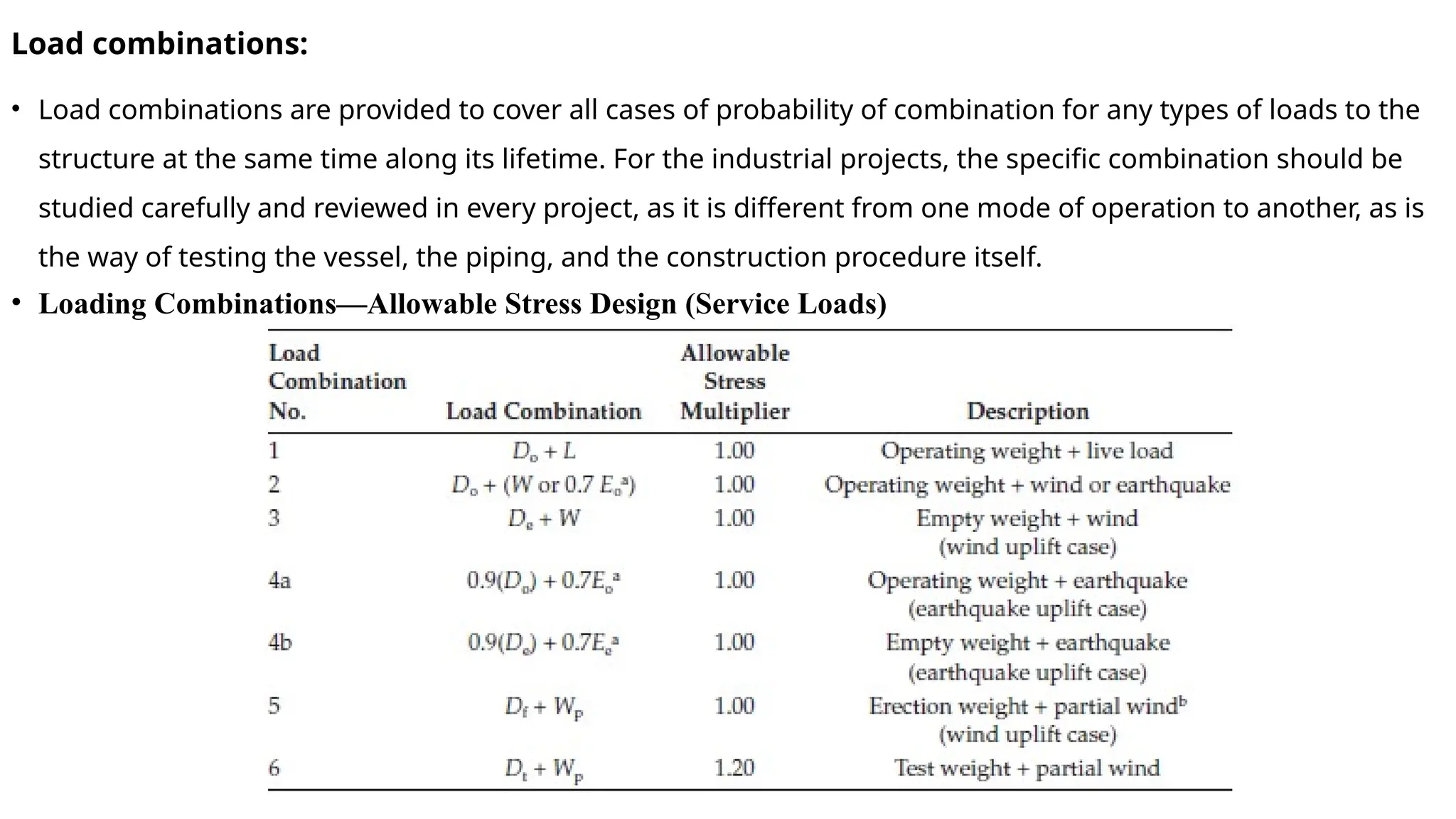
Load combinations:
• Loadcombinations are provided to cover all cases of probability of combination for any types of loads to the
structure at the same time along its lifetime. For the industrial projects, the specific combination should be
studied carefully and reviewed in every project, as it is different from one mode of operation to another, as is
the way of testing the vessel, the piping, and the construction procedure itself.
• Loading Combinations—Allowable Stress Design (Service Loads)
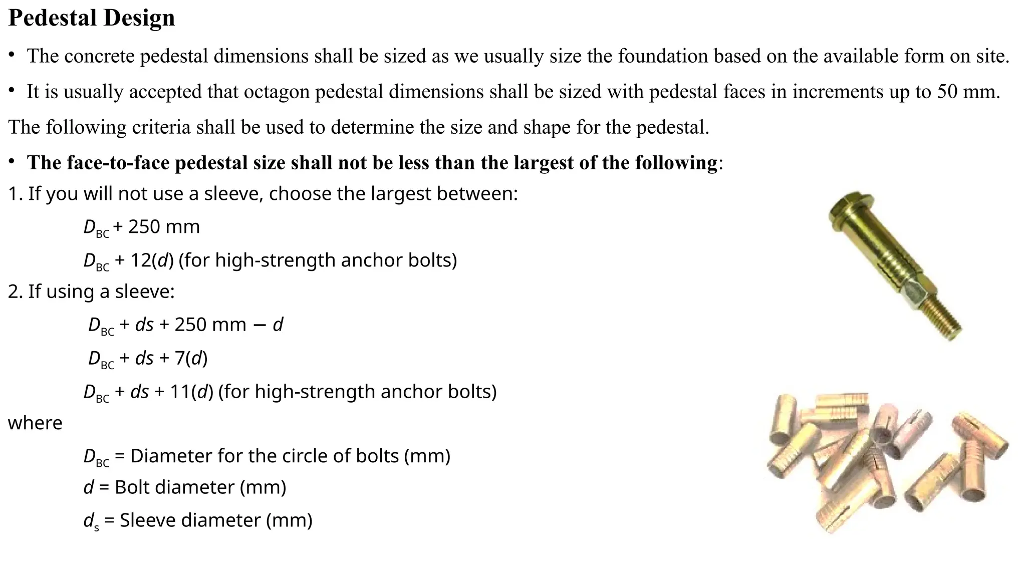
Pedestal Design
• Theconcrete pedestal dimensions shall be sized as we usually size the foundation based on the available form on site.
• It is usually accepted that octagon pedestal dimensions shall be sized with pedestal faces in increments up to 50 mm.
The following criteria shall be used to determine the size and shape for the pedestal.
• The face-to-face pedestal size shall not be less than the largest of the following:
1. If you will not use a sleeve, choose the largest between:
DBC + 250 mm
DBC + 12(d) (for high-strength anchor bolts)
2. If using a sleeve:
DBC + ds + 250 mm − d
DBC + ds + 7(d)
DBC + ds + 11(d) (for high-strength anchor bolts)
where
DBC = Diameter for the circle of bolts (mm)
d = Bolt diameter (mm)
ds = Sleeve diameter (mm)
9.
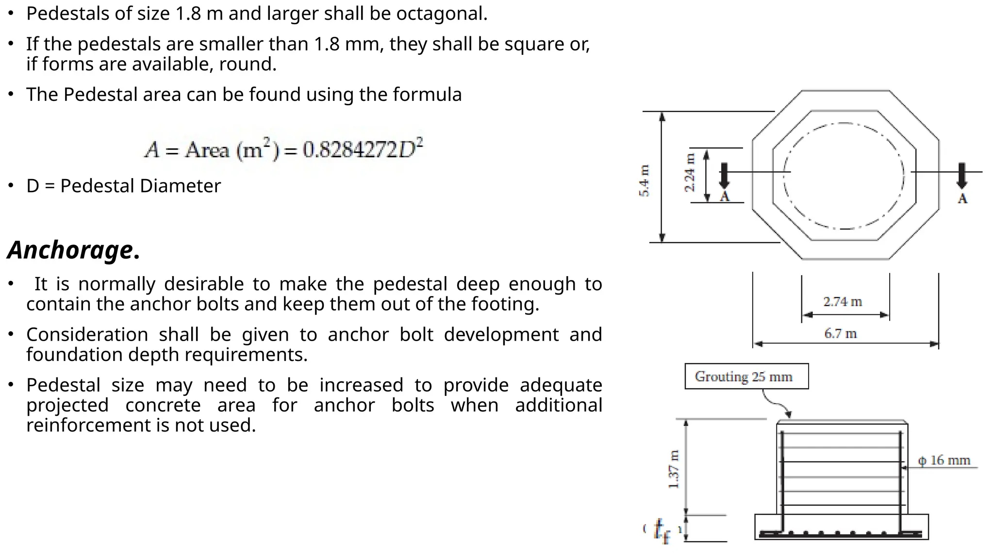
• Pedestals ofsize 1.8 m and larger shall be octagonal.
• If the pedestals are smaller than 1.8 mm, they shall be square or,
if forms are available, round.
• The Pedestal area can be found using the formula
• D = Pedestal Diameter
Anchorage.
• It is normally desirable to make the pedestal deep enough to
contain the anchor bolts and keep them out of the footing.
• Consideration shall be given to anchor bolt development and
foundation depth requirements.
• Pedestal size may need to be increased to provide adequate
projected concrete area for anchor bolts when additional
reinforcement is not used.
10.
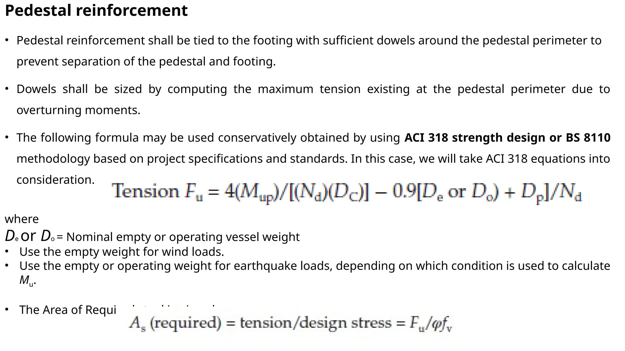
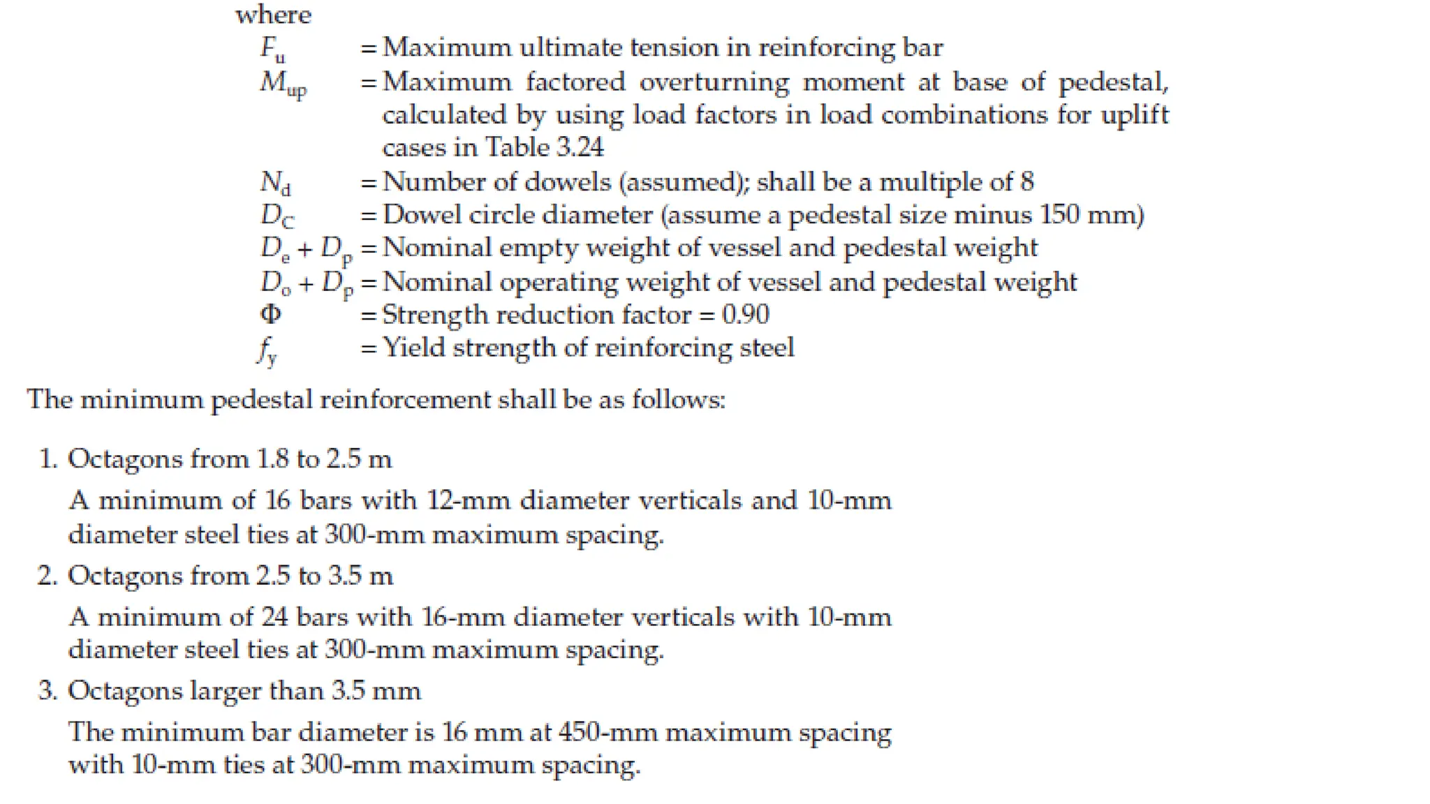
Pedestal reinforcement
• Pedestalreinforcement shall be tied to the footing with sufficient dowels around the pedestal perimeter to
prevent separation of the pedestal and footing.
• Dowels shall be sized by computing the maximum tension existing at the pedestal perimeter due to
overturning moments.
• The following formula may be used conservatively obtained by using ACI 318 strength design or BS 8110
methodology based on project specifications and standards. In this case, we will take ACI 318 equations into
consideration.
where
De or Do = Nominal empty or operating vessel weight
• Use the empty weight for wind loads.
• Use the empty or operating weight for earthquake loads, depending on which condition is used to calculate
Mu.
• The Area of Required steel is given by
12.
• Top reinforcement,a mat of reinforcing steel at the top of the pedestal, shall be provided. This entails a
minimum of steel bars with 12-mm diameter at 300-mm maximum spacing across the flats in two directions
only.
13.
Footing Design:
• Thesize of spread footings may be governed by stability requirements, sliding, soil-bearing
pressure, or settlement.
• Footings for vertical vessels shall be octagonal or square and sized based on standard available
form sizes.
• Where a footing is required, the footing thickness shall be a minimum of 300 mm.
For the first trial, the diameter (D) of an octagonal footing may be approximated by the
following formula:
• where
• Mftg = Nominal overturning moment at base of footing (mt)
• qall = Allowable gross soil-bearing (ton/m2
)
• After determining the trial diameter, calculate the area of pedestal footing.
Then check the footing against soil bearing and stability.
14.
Check for soilBearing and Stability:
• The stability factor of safety can be calculated from the following
equation:
FS = D/2e where e = Eccentricity (Mftg/P)
• The minimum stability safety factor against overturning for service
loads other than earthquake shall be 1.5.
• Soil-bearing pressure shall be computed using the following formula:
q = LP/A,
It should be lesser than the given soil bearing pressure.
The L value is determined by knowing e/D
values, and by referring the Table. Provided that
the e/D > 0.122
15.
Check for FoundationSliding
• The minimum safety factor against sliding for service loads other than earthquake
shall be 1.5.
• The coefficient of friction used in computing the safety factor against sliding for
cast-in-place foundations shall be 0.40, unless specified otherwise in a detailed
soil investigation.
16.
•For a givendesign data of the vertical vessel:
•Empty weight = 60 tons, Operating weight = 156.57 tons, Test weight = 283 tons, unit weight of structure = 2 ton/m3
, steel yield
strength = 420 N/mm2
, Wind Load by SEI/ASCE 7-02 = 20.3 ton, Moment at base =262.94 mt, Anchor Bolt: 65-mm, type,
ϕ
ASTM F1554 Grade 36, with a 100 mm × 400 mm long sleeve and 350-mm projection on 4.53 m bolt circle. Assume number
ϕ ϕ
of dowels as 40.
• Design a suitable pedestal with reinforcement details.


![Unit-2 [Dynamic Equipment Foundation].pdf](https://cdn.slidesharecdn.com/ss_thumbnails/unit-2dynamicequipmentfoundation-231010072957-6de83d97-thumbnail.jpg?width=640&height=640&fit=bounds)


