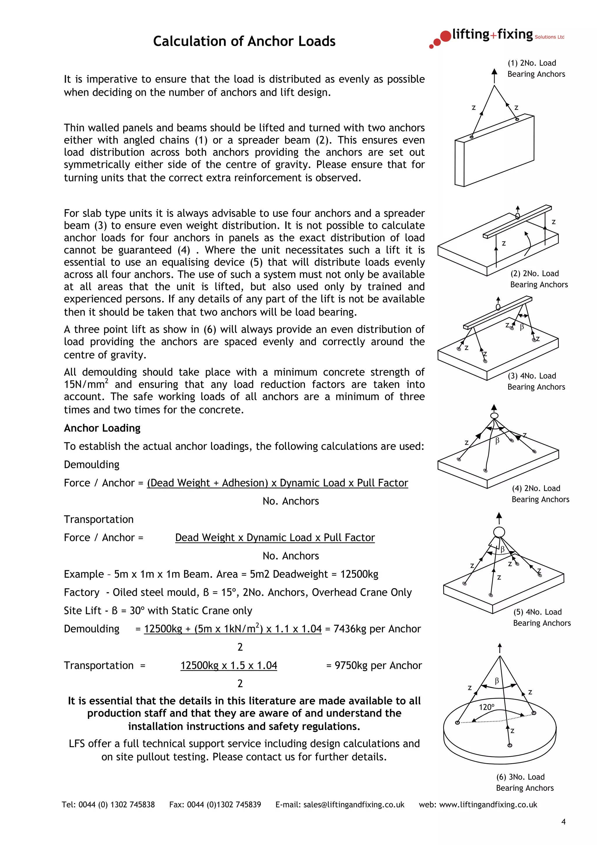
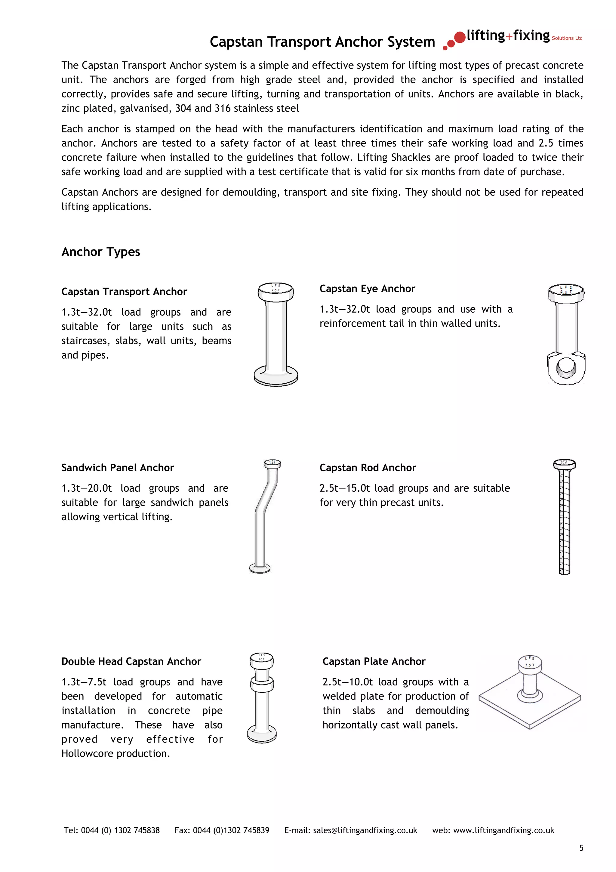
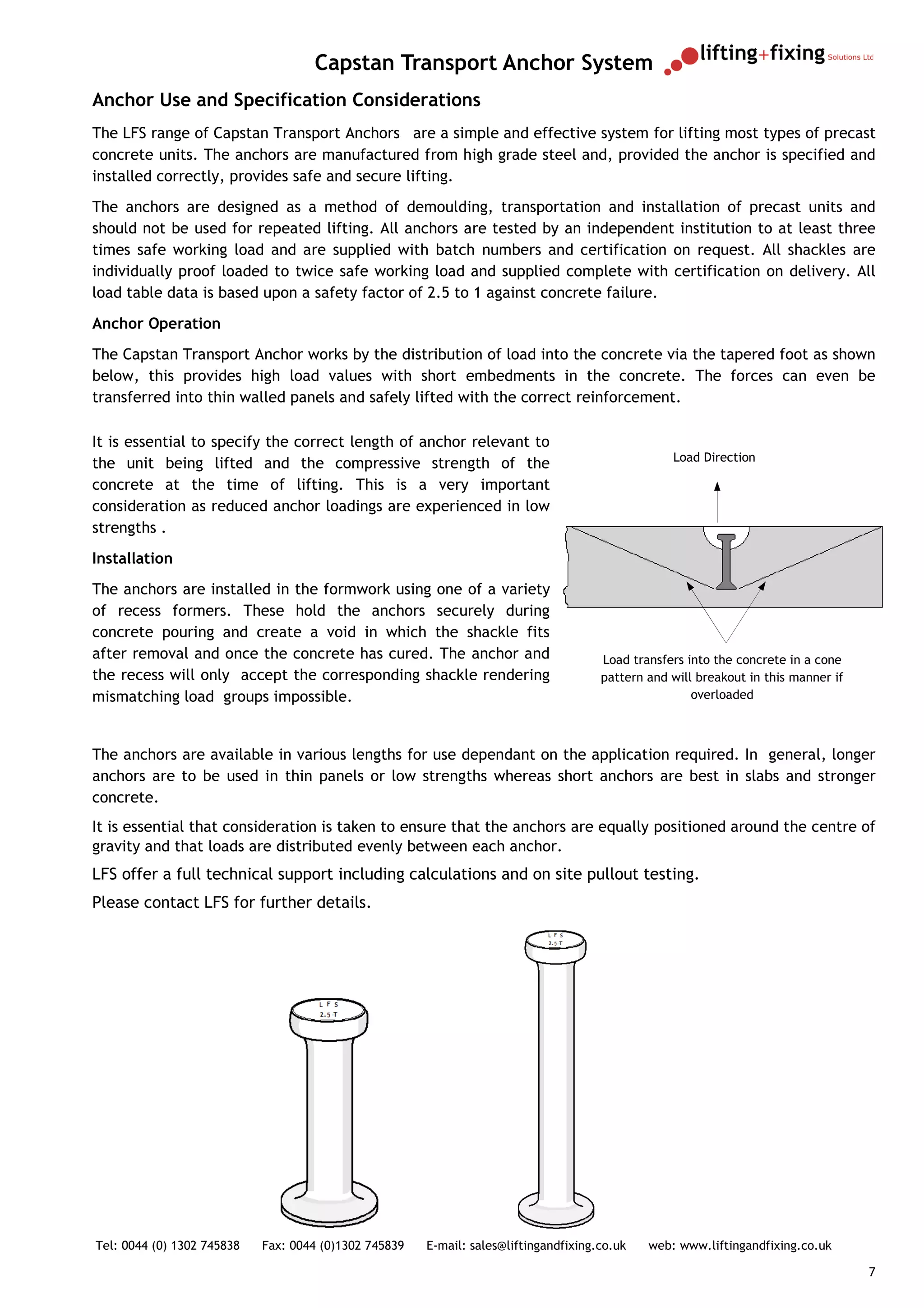
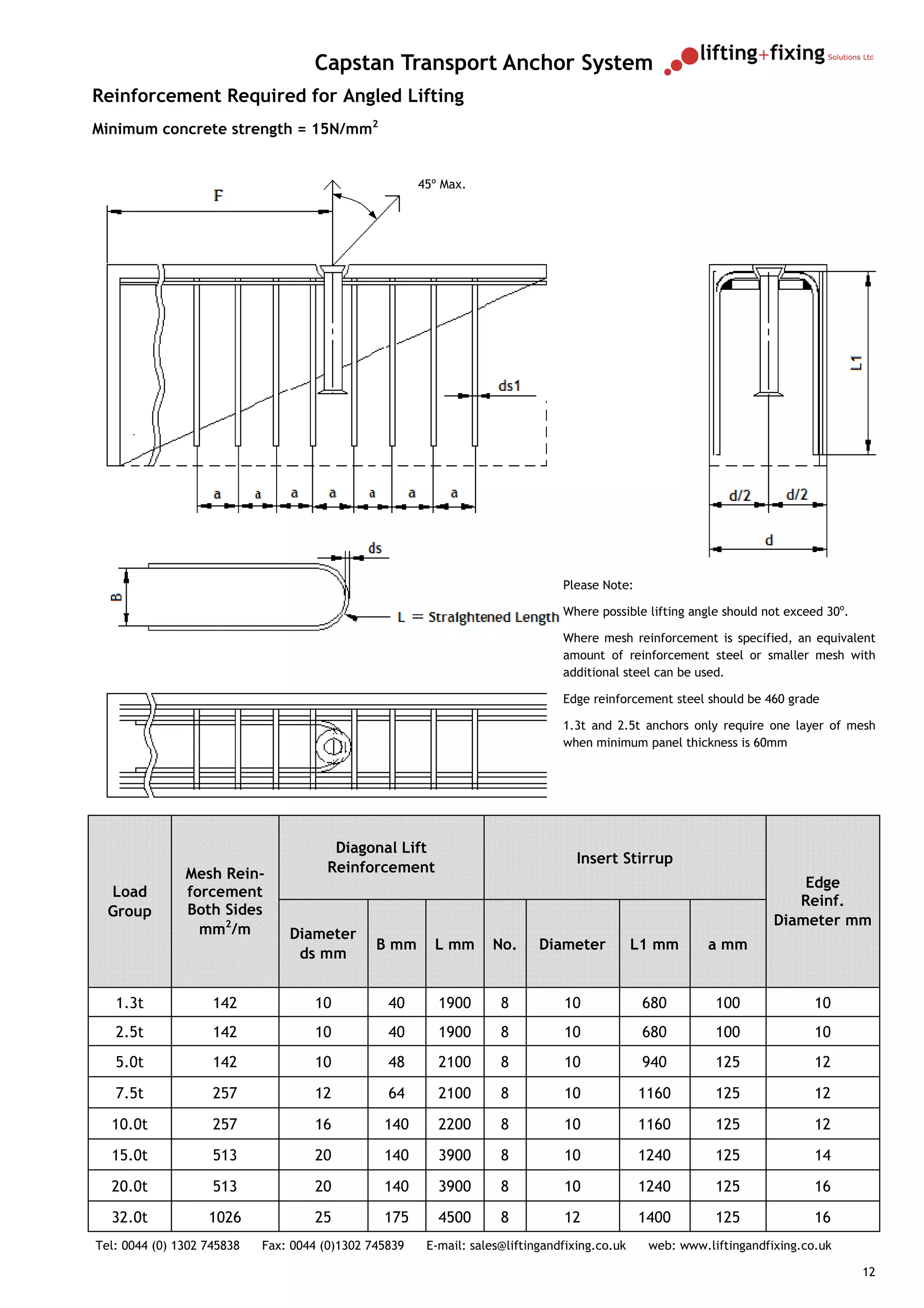
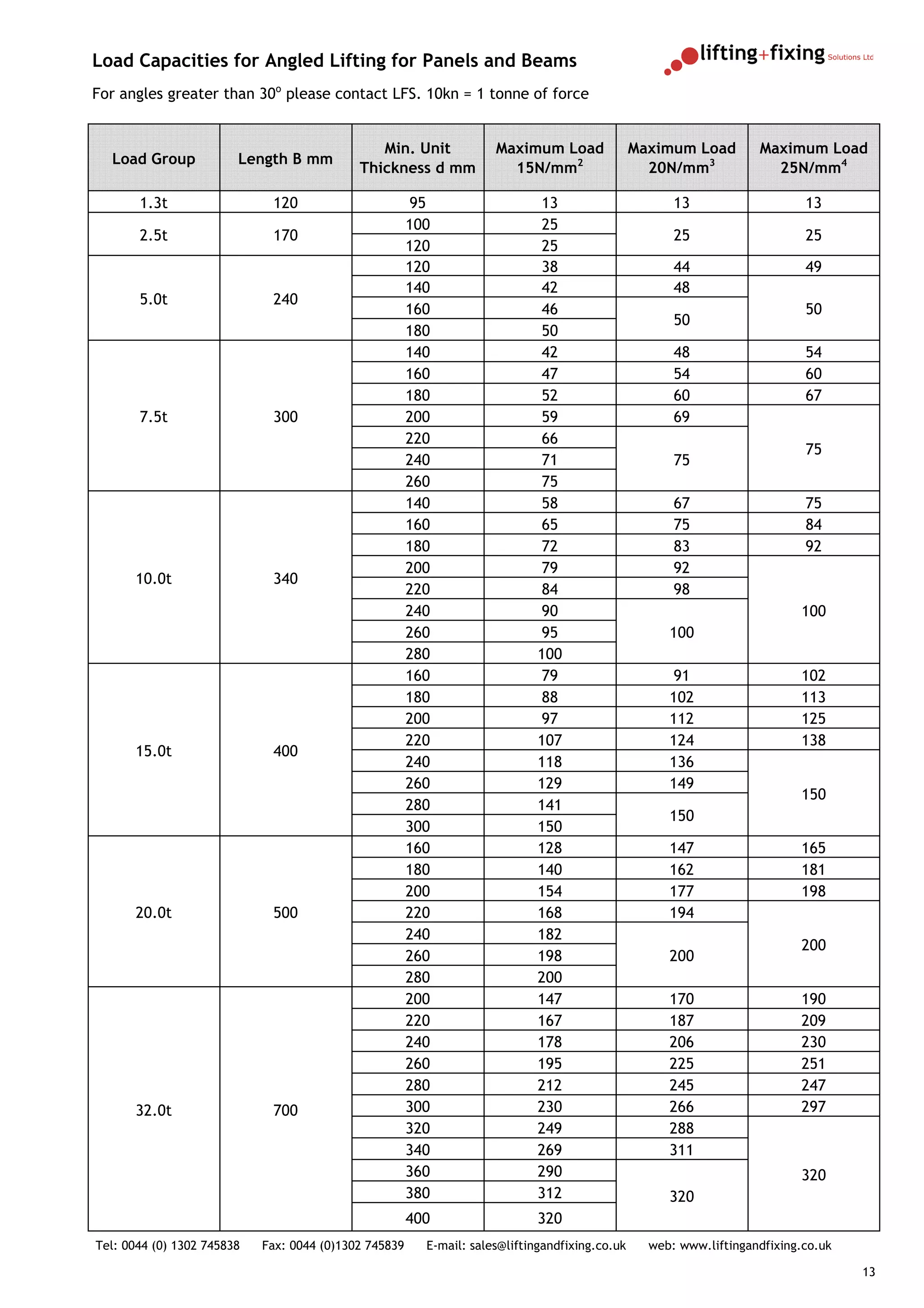
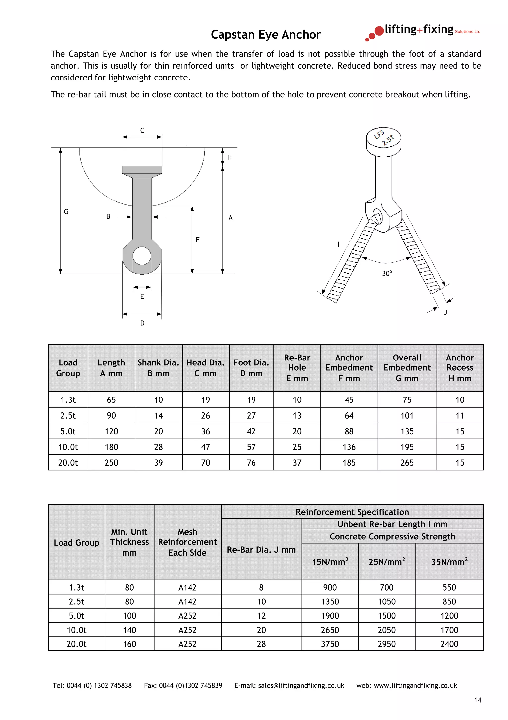
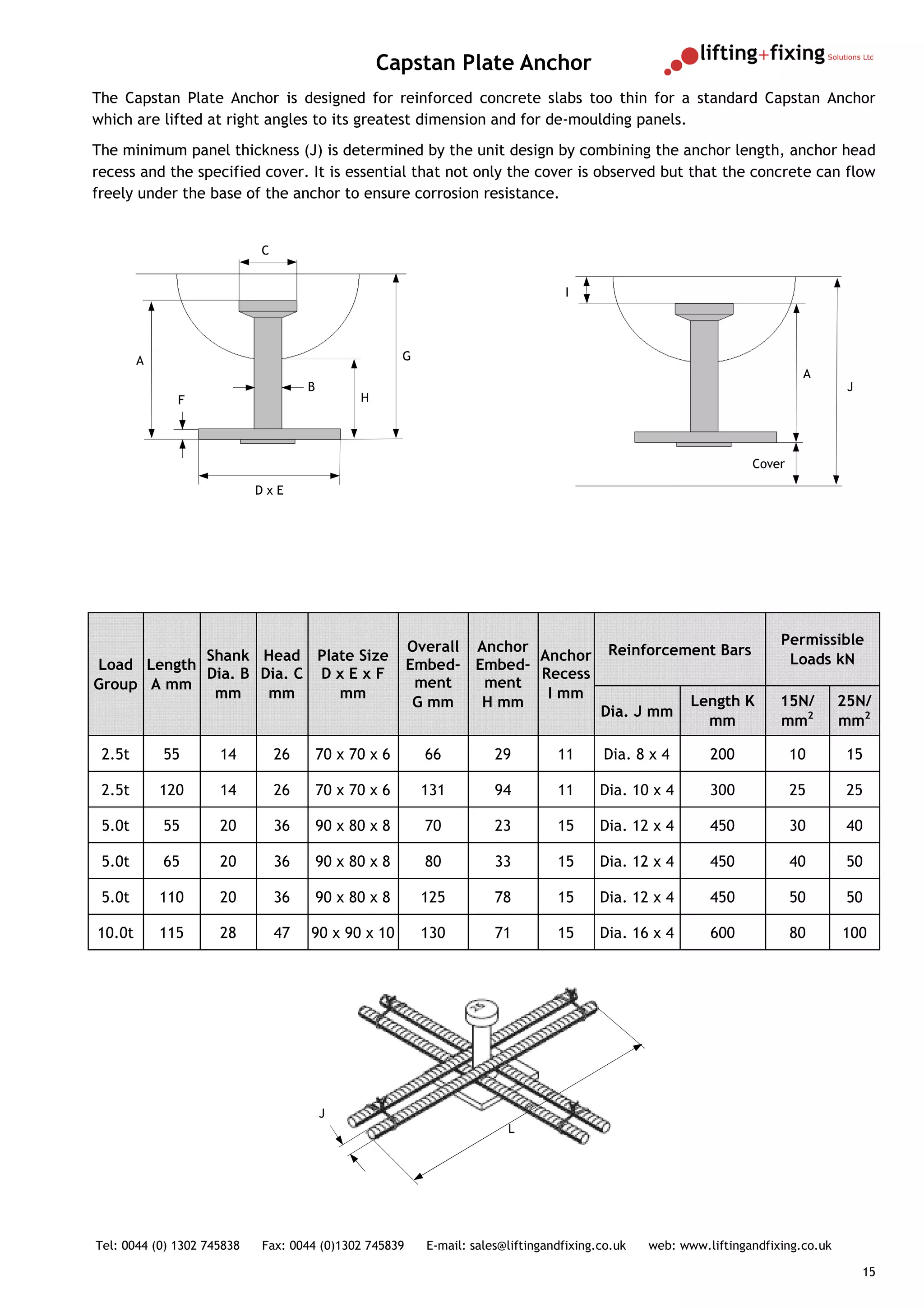
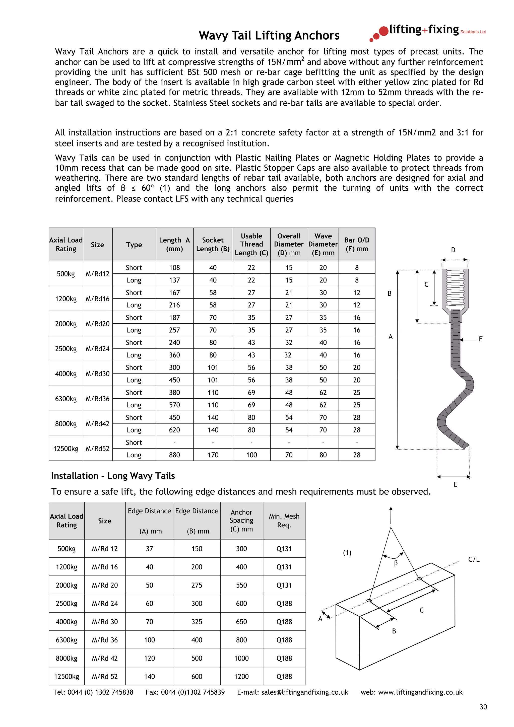
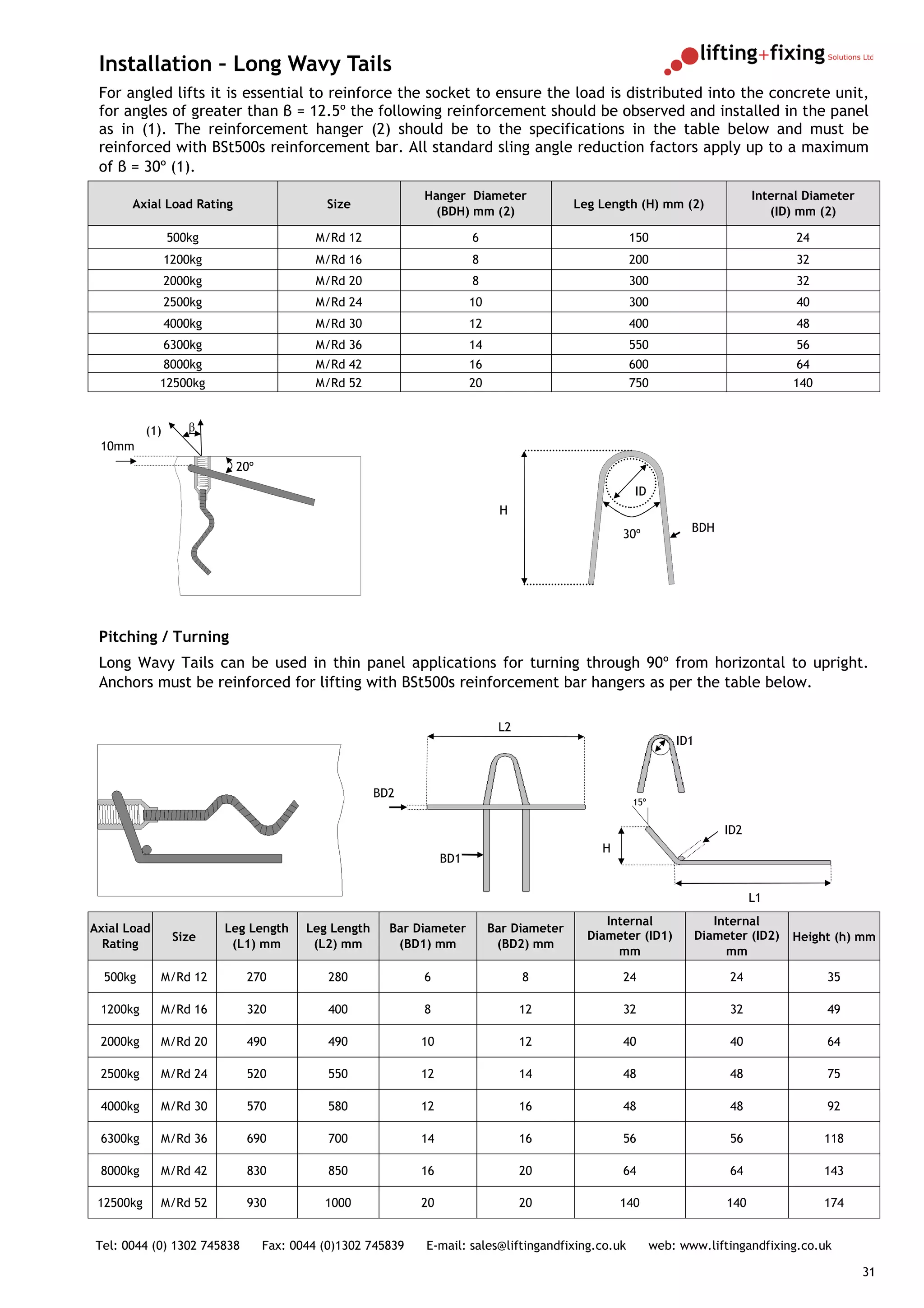
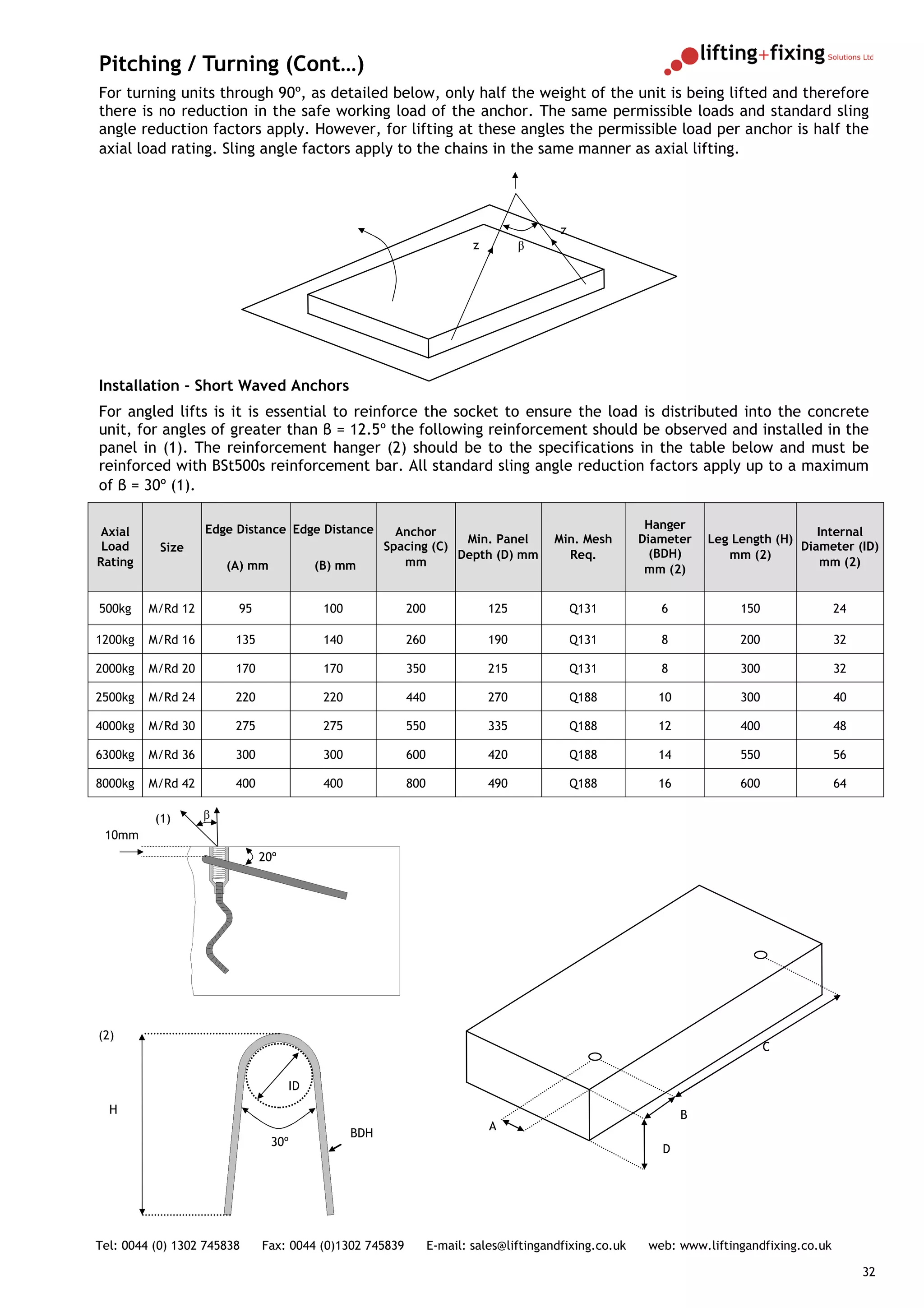
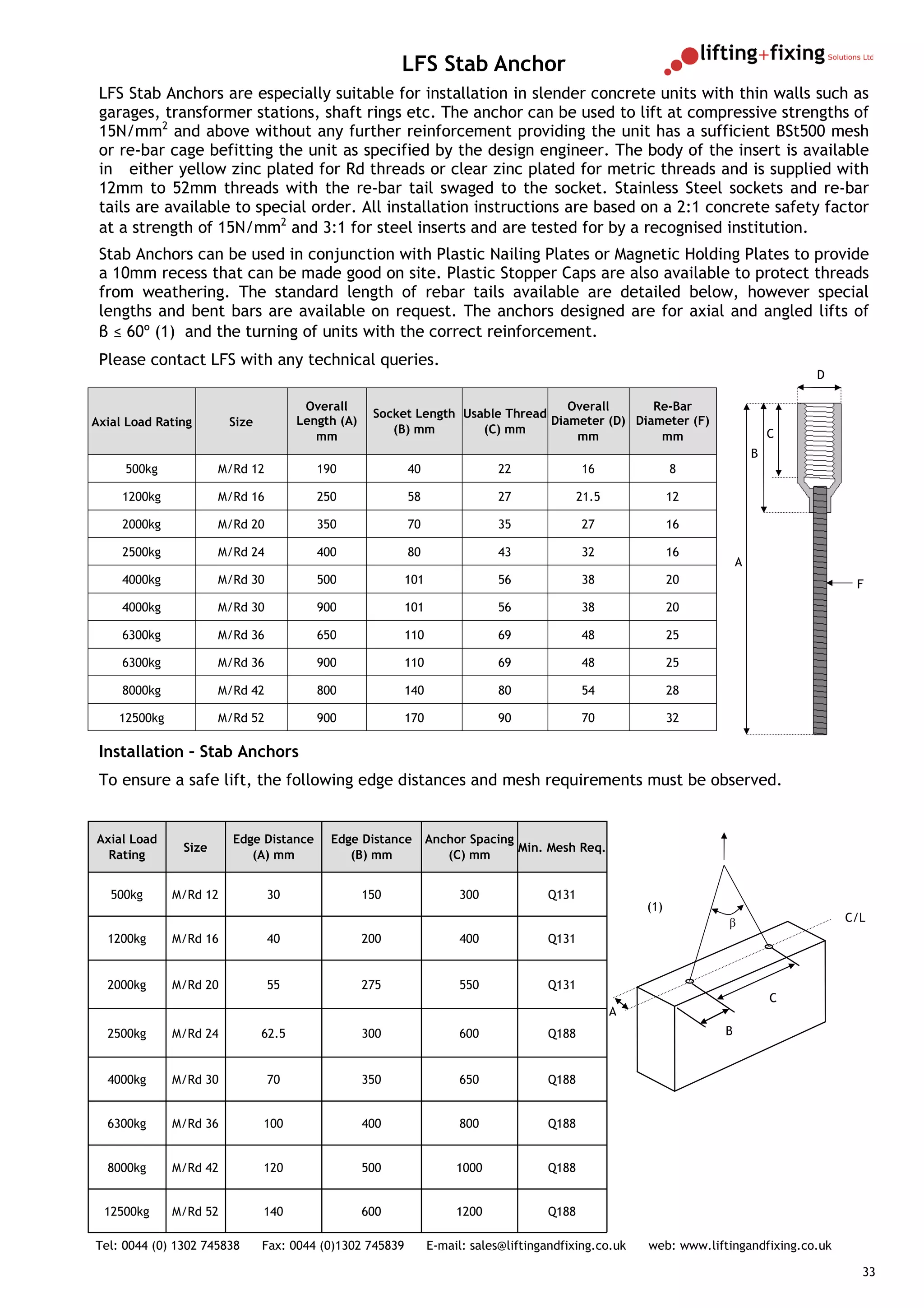
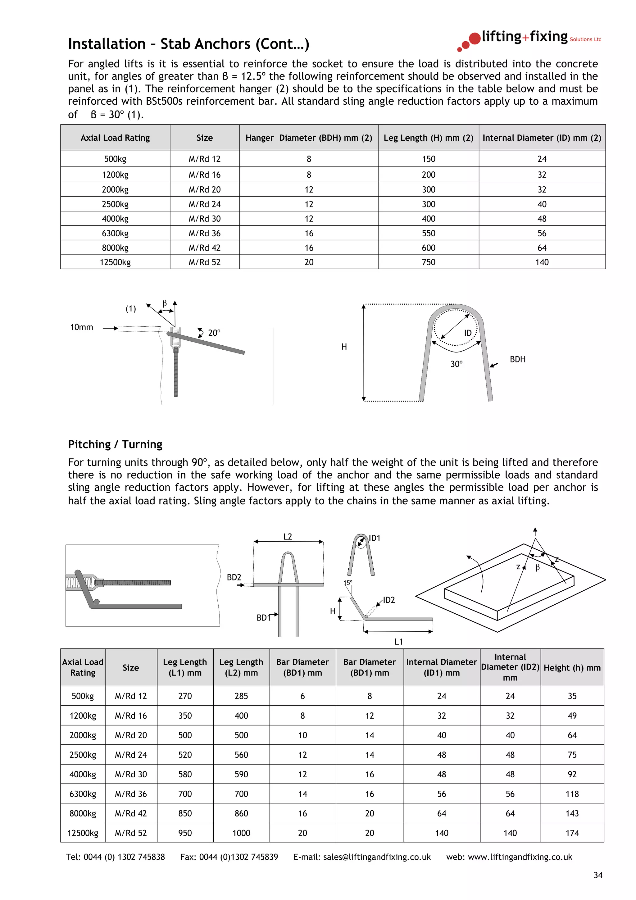
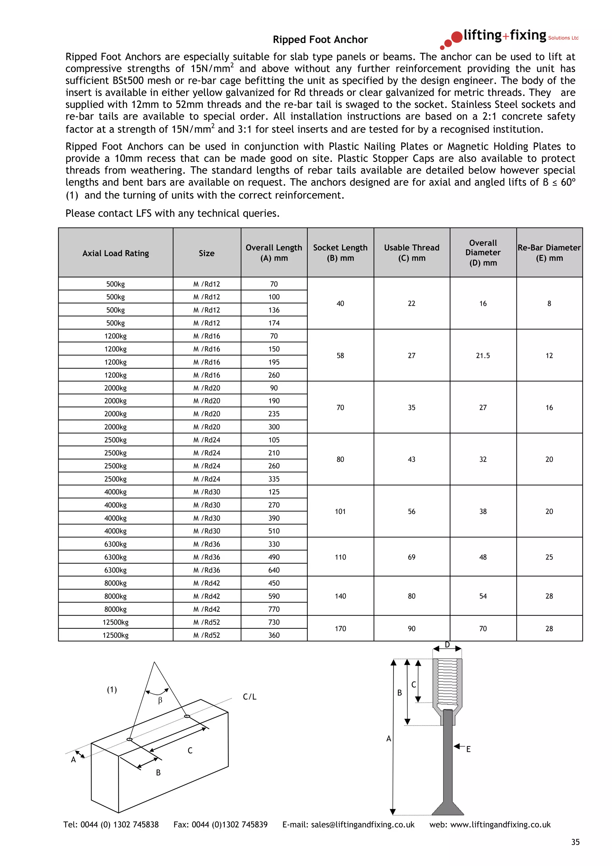
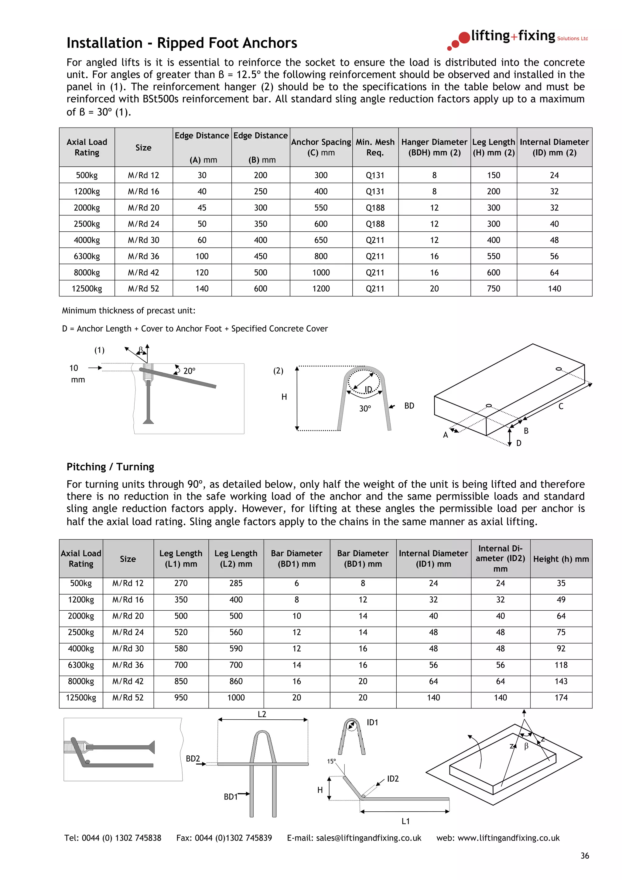
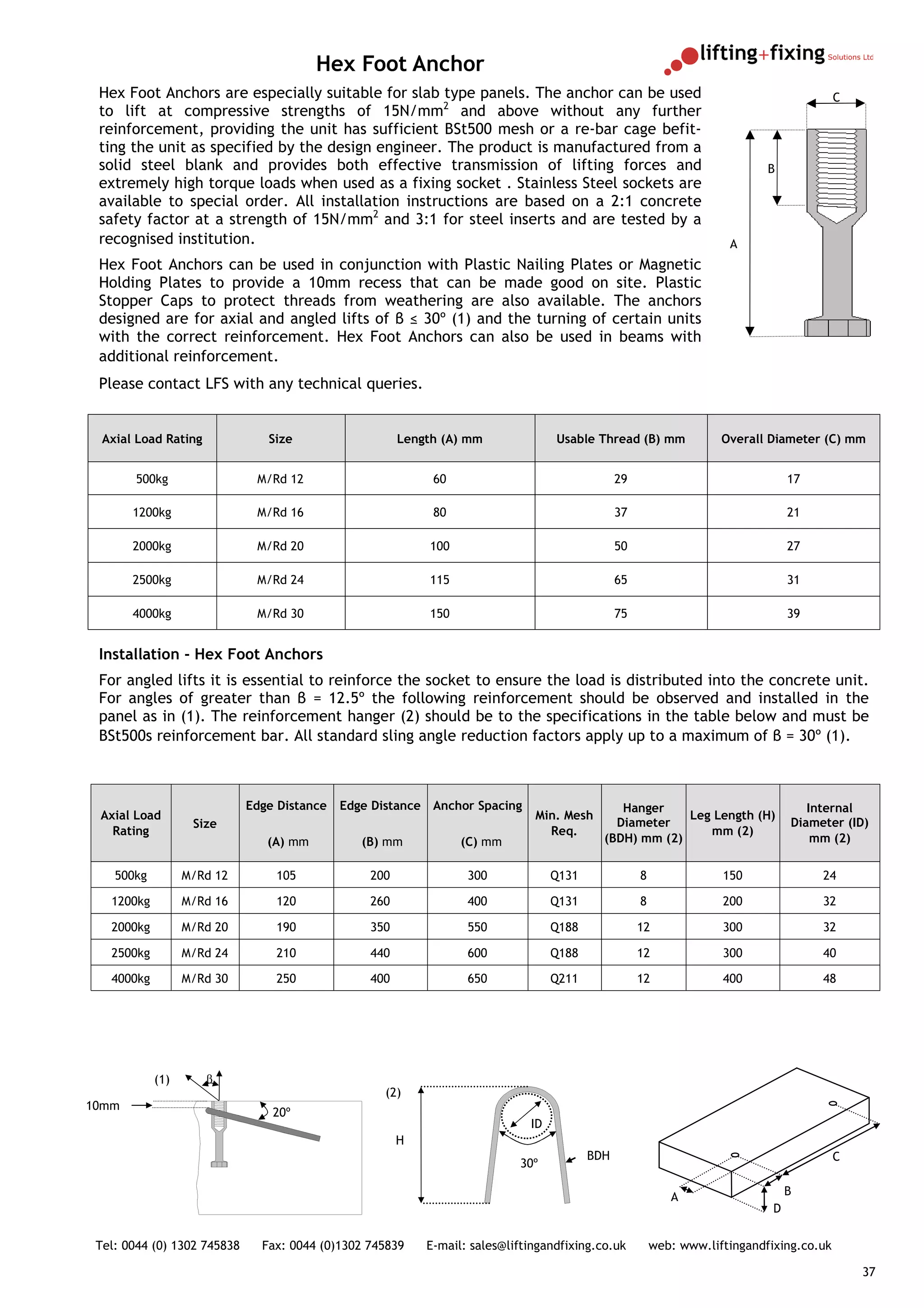
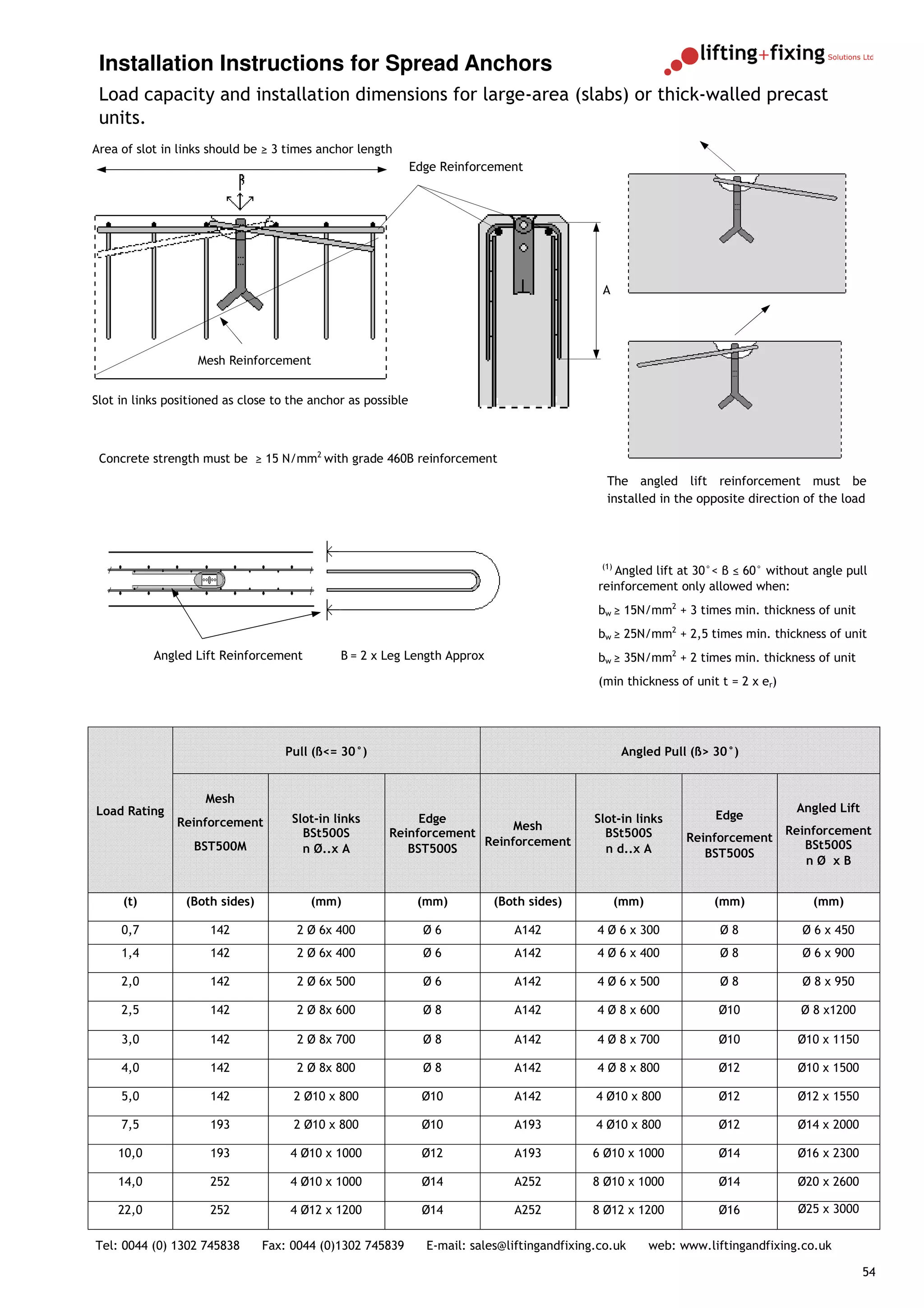
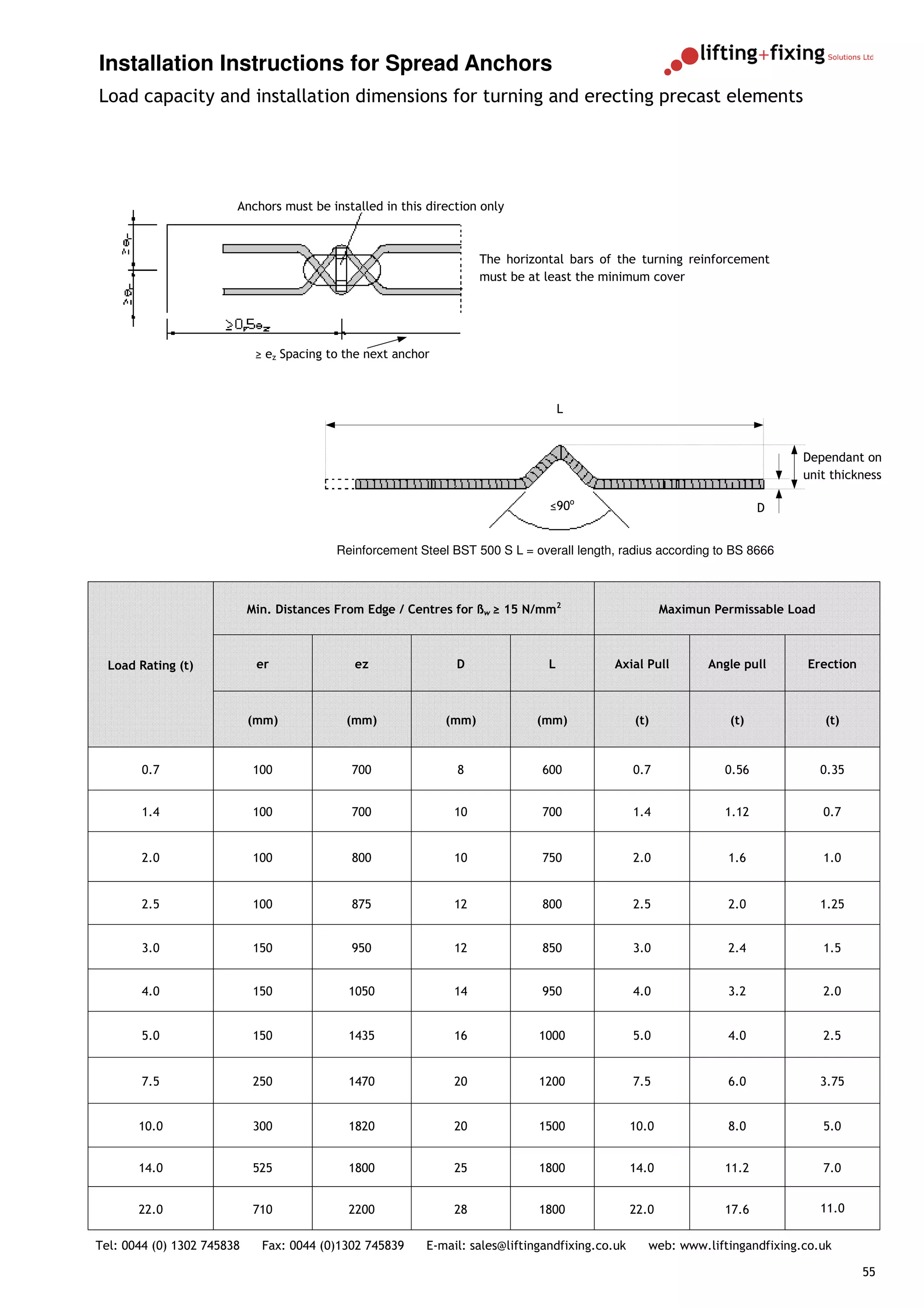
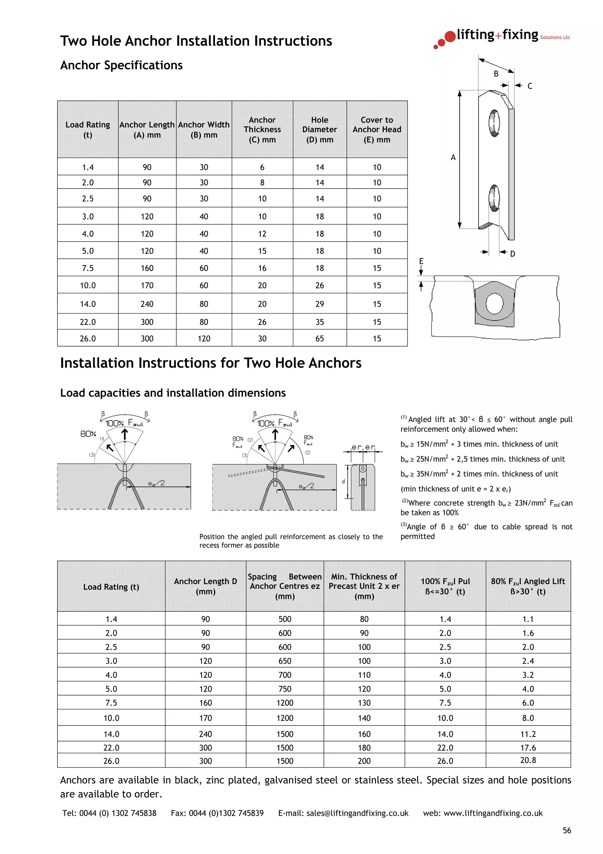
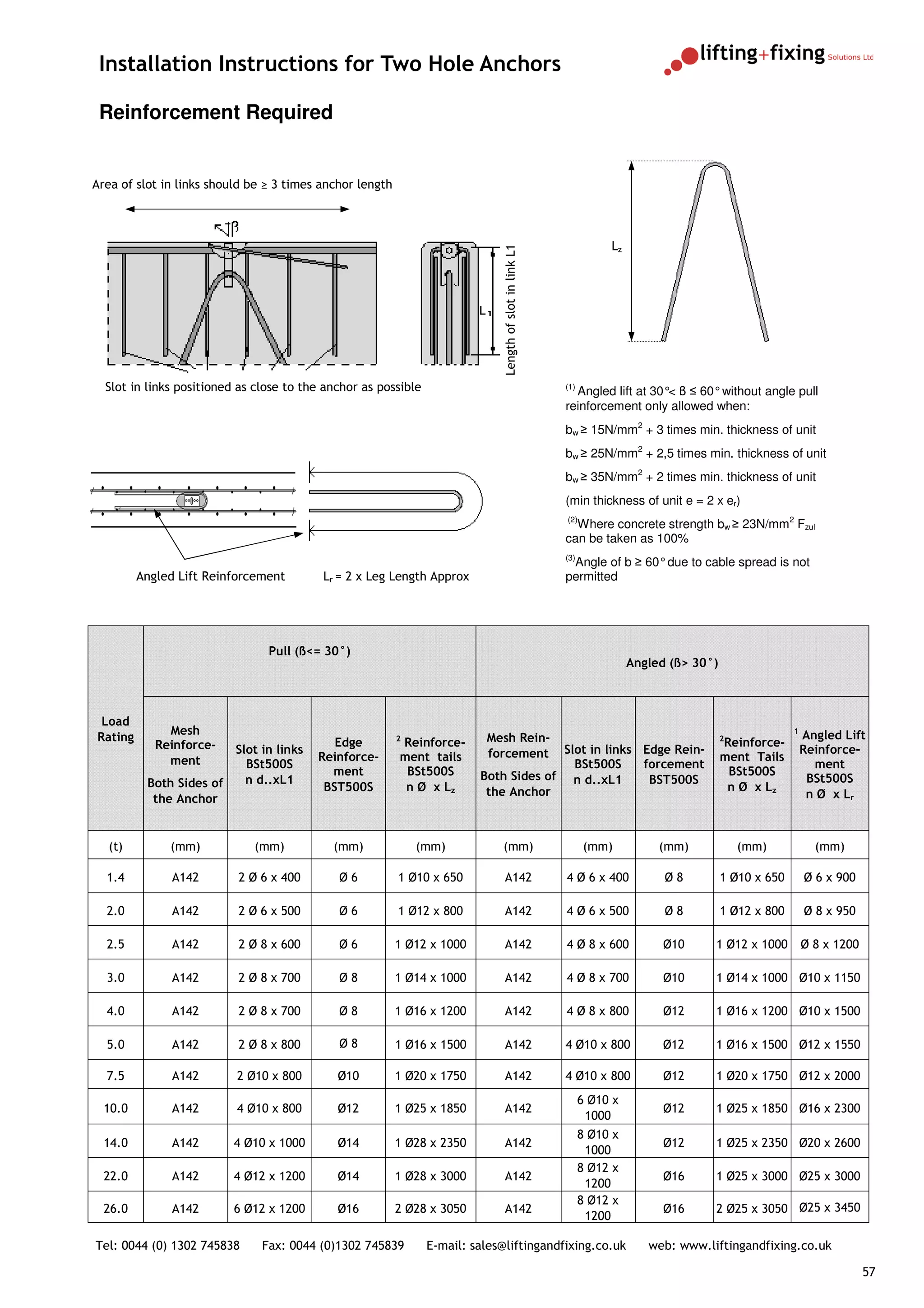
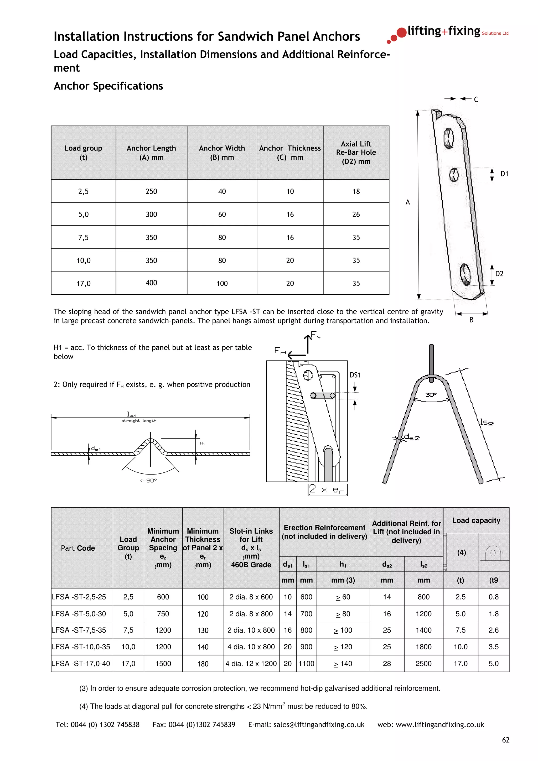
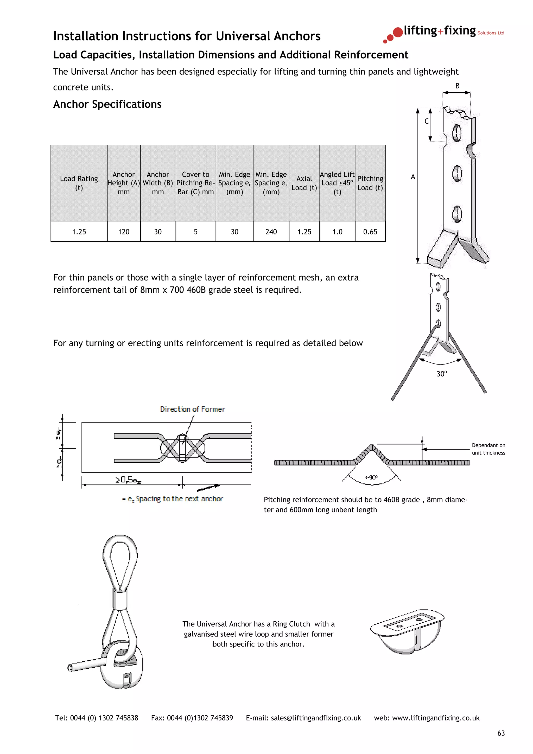
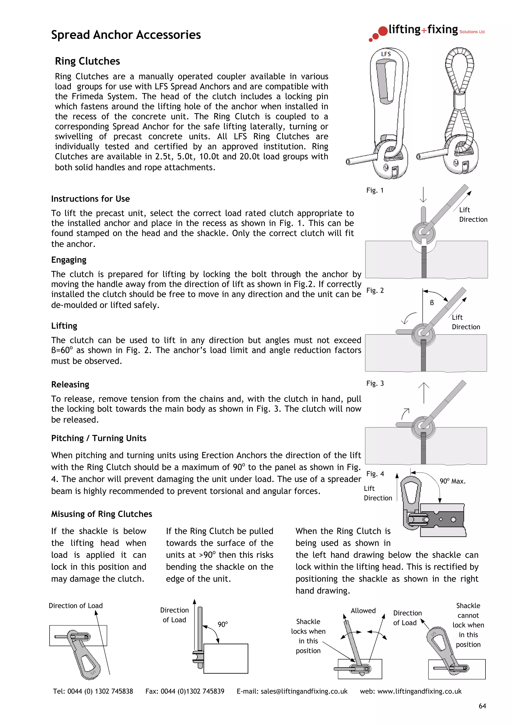
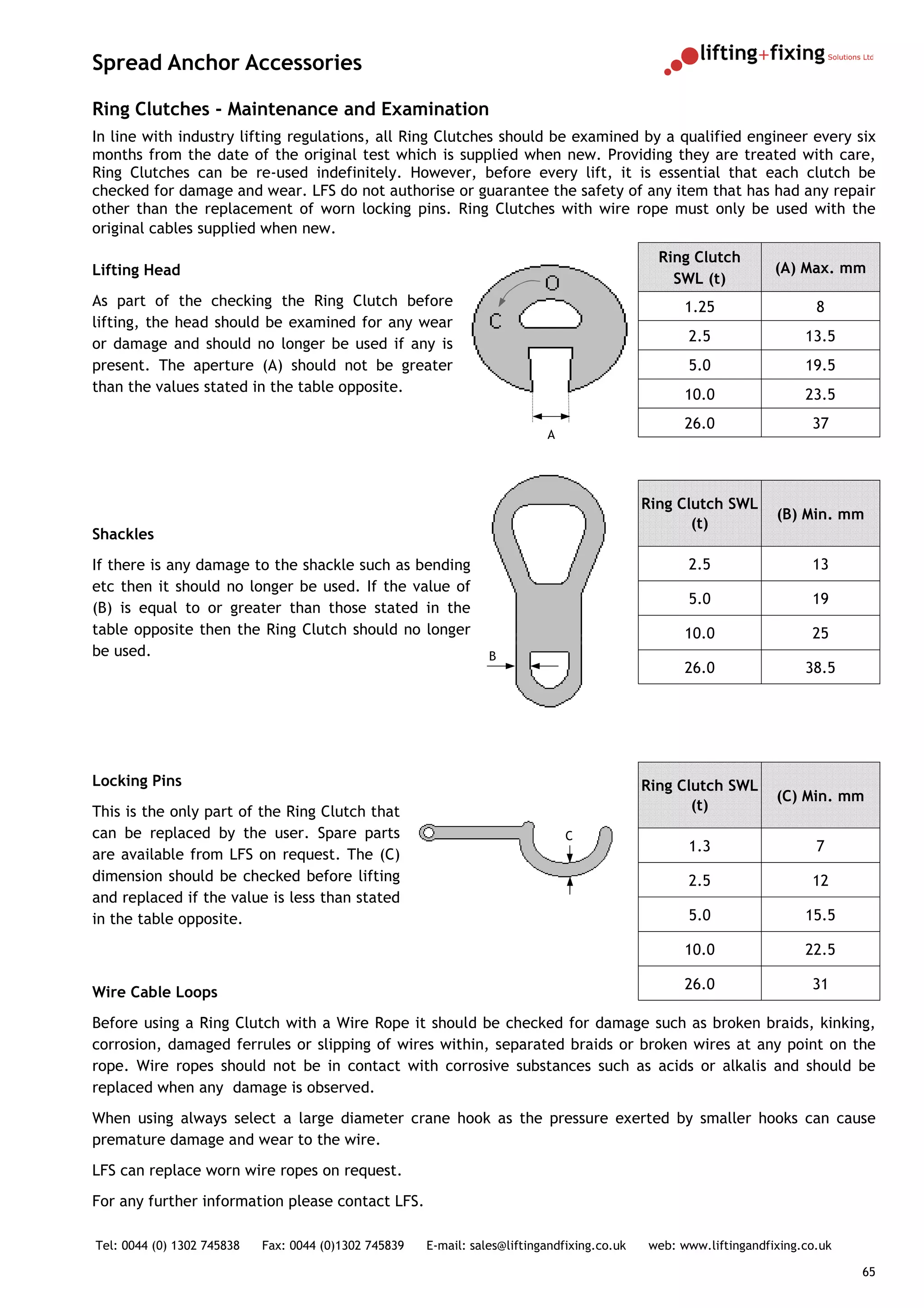
PRODUCT GUIDE AND
PRECAST TECHNICAL MANUAL


The professional choice for all your precast
     concrete anchors and accessories


Tel: 0044 (0) 1302 745838   Fax: 0044 (0)1302 745839   E-mail: sales@liftingandfixing.co.uk   web: www.liftingandfixing.co.uk

                                                                                                                                1
LFS Product and Technical Manual


                                                       Contents


   Page 3-4                                             Precast Concrete Lifting Design


   Page 5-22                                           Capstan Transport Anchor Systems


    Page 23—41                                                Threaded Lifting Systems


    Page 46—62                                                   Spread Anchor System


        Page 63                                                     Plastic Accessories


Tel: 0044 (0) 1302 745838   Fax: 0044 (0)1302 745839   E-mail: sales@liftingandfixing.co.uk   web: www.liftingandfixing.co.uk

                                                                                                                                2
Precast Concrete Lifting Design

The selection of lifting devices should be carefully made dependant on the type of lift or lifts that the unit will
be subject to once manufactured. It is vitally important to ensure both safe lifting and that no damage to the
concrete occurs. When assessing the lifting of a unit the following factors must be considered.


The Weight of the Unit
The dead weight of a normal precast unit should be calculated using a concrete density of 2500kN/m2. The
theoretical weight can be calculated either mathematically via the dimensions of the unit or through design
packages. The adhesion to the mould must also be included in the calculation of forces dependant on the type
of mould that the unit is cast in. The following can be used as a guide:


Oiled steel mould                      = 1kN/m2
Varnished timber mould                 = 2kn/m2
Rough timber mould                     = 3kn/m2
The value of adhesion to the mould is calculated by multiplying the area of the concrete in contact with the
mould by the adhesion factor = Area x Mould Adhesion Factor
Double T Beam should be calculated using 2 x deadweight and Coffered units should be 4 x deadweight.


Dynamic Loads
These should be calculated in most lifts of precast units, they are controlled by both the velocity and quality
of lifting equipment and the terrain being transported across.
The following factors should be used:
       Demoulding                      = x 1.1
       Turning                         = x 1.3
       Site Transportation             = x 1.5       (With a stationary crane)
       Site Transportation             = x 1.65      (Over even ground)


These are based on using overhead or static cranes at speeds of <=90m/min. For rough ground or when the site
installation details are not known, always use a factor of Dynamic Load ≥ x 2.
The true mass of a precast unit for anchor specification is worked out as follows:
       (Demoulding) Mass               = (Deadweight +Adhesion Factor) x Dynamic Load
       (Transportation) Mass           = Deadweight x Dynamic Load


Sling Angle
The angle is dependant on the length of chains / cables that are used to lift the unit. The shorter the chains
the greater the tensile load becomes on each anchor point. The following table show the factors by which the
pull factor should be calculated.
Angle β                Pull Factor (z)
0º                     1.00                                                                                 β
                                                                                                                   z
15º                    1.01                                                                             z

30                     1.04
45º                    1.08
60                     1.16
90º                    1.41
(Consult LFS for angles above 90º)

Tel: 0044 (0) 1302 745838     Fax: 0044 (0)1302 745839   E-mail: sales@liftingandfixing.co.uk   web: www.liftingandfixing.co.uk

                                                                                                                                  3
Calculation of Anchor Loads
                                                                                                                                   (1) 2No. Load
                                                                                                                                   Bearing Anchors
It is imperative to ensure that the load is distributed as evenly as possible
when deciding on the number of anchors and lift design.
                                                                                                                z                          z

Thin walled panels and beams should be lifted and turned with two anchors
either with angled chains (1) or a spreader beam (2). This ensures even
load distribution across both anchors providing the anchors are set out
symmetrically either side of the centre of gravity. Please ensure that for
turning units that the correct extra reinforcement is observed.


For slab type units it is always advisable to use four anchors and a spreader
                                                                                                                                                           z
beam (3) to ensure even weight distribution. It is not possible to calculate
anchor loads for four anchors in panels as the exact distribution of load                                                      z
cannot be guaranteed (4) . Where the unit necessitates such a lift it is
essential to use an equalising device (5) that will distribute loads evenly
across all four anchors. The use of such a system must not only be available                                                           (2) 2No. Load
at all areas that the unit is lifted, but also used only by trained and                                                                Bearing Anchors
experienced persons. If any details of any part of the lift is not be available
then it should be taken that two anchors will be load bearing.
                                                                                                                                   z           β
A three point lift as show in (6) will always provide an even distribution of
                                                                                                                                                       z
load providing the anchors are spaced evenly and correctly around the                                      z
centre of gravity.                                                                                                   z

All demoulding should take place with a minimum concrete strength of                                                               (3) 4No. Load
15N/mm2 and ensuring that any load reduction factors are taken into                                                                Bearing Anchors
account. The safe working loads of all anchors are a minimum of three
times and two times for the concrete.
Anchor Loading
                                                                                                                                               z
                                                                                                           z               β
To establish the actual anchor loadings, the following calculations are used:
Demoulding
Force / Anchor = (Dead Weight + Adhesion) x Dynamic Load x Pull Factor                                                                 (4) 2No. Load
                                                       No. Anchors                                                                     Bearing Anchors

Transportation
Force / Anchor =             Dead Weight x Dynamic Load x Pull Factor
                                                                                                                               β
                                                       No. Anchors
                                                                                                               z                   z
                                                                                                                                                       z
Example – 5m x 1m x 1m Beam. Area = 5m2 Deadweight = 12500kg                                                               z

Factory - Oiled steel mould, β = 15º, 2No. Anchors, Overhead Crane Only
Site Lift - β = 30º with Static Crane only                                                                                             (5) 4No. Load
                                                  2                                                                                    Bearing Anchors
Demoulding         = 12500kg + (5m x 1kN/m ) x 1.1 x 1.04 = 7436kg per Anchor
                                             2
Transportation =              12500kg x 1.5 x 1.04                     = 9750kg per Anchor
                                             2                                                                             β
                                                                                                            z
                                                                                                                                                   z
 It is essential that the details in this literature are made available to all
                                                                                                                    120º
      production staff and that they are aware of and understand the
               installation instructions and safety regulations.                                                                       z
 LFS offer a full technical support service including design calculations and
        on site pullout testing. Please contact us for further details.
                                                                                                                           (6) 3No. Load
                                                                                                                           Bearing Anchors

Tel: 0044 (0) 1302 745838   Fax: 0044 (0)1302 745839     E-mail: sales@liftingandfixing.co.uk   web: www.liftingandfixing.co.uk

                                                                                                                                                               4
Capstan Transport Anchor System
The Capstan Transport Anchor system is a simple and effective system for lifting most types of precast concrete
unit. The anchors are forged from high grade steel and, provided the anchor is specified and installed
correctly, provides safe and secure lifting, turning and transportation of units. Anchors are available in black,
zinc plated, galvanised, 304 and 316 stainless steel
Each anchor is stamped on the head with the manufacturers identification and maximum load rating of the
anchor. Anchors are tested to a safety factor of at least three times their safe working load and 2.5 times
concrete failure when installed to the guidelines that follow. Lifting Shackles are proof loaded to twice their
safe working load and are supplied with a test certificate that is valid for six months from date of purchase.
Capstan Anchors are designed for demoulding, transport and site fixing. They should not be used for repeated
lifting applications.


Anchor Types


Capstan Transport Anchor                                        Capstan Eye Anchor

1.3t—32.0t load groups and are                                  1.3t—32.0t load groups and use with a
suitable for large units such as                                reinforcement tail in thin walled units.
staircases, slabs, wall units, beams
and pipes.


Sandwich Panel Anchor                                           Capstan Rod Anchor
1.3t—20.0t load groups and are                                  2.5t—15.0t load groups and are suitable
suitable for large sandwich panels                              for very thin precast units.
allowing vertical lifting.


Double Head Capstan Anchor                                       Capstan Plate Anchor
1.3t—7.5t load groups and have                                   2.5t—10.0t load groups with a
been developed for automatic                                     welded plate for production of
installation in concrete pipe                                    thin slabs and demoulding
manufacture. These have also                                     horizontally cast wall panels.
proved very effective for
Hollowcore production.


Tel: 0044 (0) 1302 745838   Fax: 0044 (0)1302 745839   E-mail: sales@liftingandfixing.co.uk   web: www.liftingandfixing.co.uk

                                                                                                                                5
Capstan Transport Anchor System


Capstan Anchor Accessories


Capstan Rubber Recess Former                                  Capstan Fixing Screw
1.3t—32.0t load groups and are for                            1.3t—32.0t load group and are for attaching
attaching the anchor to the mould                             the former through the mould. The screw
before casting. The former creates                            holds the anchor tightly to the formwork
a void in the precast to accept the                           when fastened with a washer and nut.
Shackle and to allow lifting through
360o.


Capstan Magnetic Recess Former                                  Capstan Steel Recess Former and
                                                                Grommet
1.3t—10.0t load groups and are for
attaching the anchor to steel                                   1.3t—10.0t load groups and are for
moulds before casting. The former                               attaching the anchor to steel moulds
creates a void in the precast to                                before casting. The former creates a void
accept the Shackle and to allow                                 in the precast to accept the Shackle and
lifting through 360o.                                           to allow lifting through 360o. This part
                                                                requires a hole in the mould through
                                                                which a fixing screw is inserted and
                                                                fastened with a washer and nut.


Double Head Capstan Magnetic Recess Former
1.3t—10.0t load groups and are for attaching the anchor to the mould. The
former creates a void in the precast to accept the Shackle and to allow lifting
through 360o. They are available with either three or six magnets dependant on
the adhesion required. A rubber version for use in wooden moulds or for quick
release floating applications such as hollow core flooring is also available.


Capstan Lifting Shackle
1.3t—32.0t load groups and are for lifting and turning concrete units with
corresponding anchors cast in. The shackle head surrounds the anchor and can rotate
through 360o. Only the correct shackle for the anchor load group will fit.


Tel: 0044 (0) 1302 745838   Fax: 0044 (0)1302 745839   E-mail: sales@liftingandfixing.co.uk   web: www.liftingandfixing.co.uk

                                                                                                                                6
Capstan Transport Anchor System
Anchor Use and Specification Considerations
The LFS range of Capstan Transport Anchors are a simple and effective system for lifting most types of precast
concrete units. The anchors are manufactured from high grade steel and, provided the anchor is specified and
installed correctly, provides safe and secure lifting.
The anchors are designed as a method of demoulding, transportation and installation of precast units and
should not be used for repeated lifting. All anchors are tested by an independent institution to at least three
times safe working load and are supplied with batch numbers and certification on request. All shackles are
individually proof loaded to twice safe working load and supplied complete with certification on delivery. All
load table data is based upon a safety factor of 2.5 to 1 against concrete failure.
Anchor Operation
The Capstan Transport Anchor works by the distribution of load into the concrete via the tapered foot as shown
below, this provides high load values with short embedments in the concrete. The forces can even be
transferred into thin walled panels and safely lifted with the correct reinforcement.

It is essential to specify the correct length of anchor relevant to
                                                                                                  Load Direction
the unit being lifted and the compressive strength of the
concrete at the time of lifting. This is a very important
consideration as reduced anchor loadings are experienced in low
strengths .
Installation
The anchors are installed in the formwork using one of a variety
of recess formers. These hold the anchors securely during
concrete pouring and create a void in which the shackle fits
after removal and once the concrete has cured. The anchor and                         Load transfers into the concrete in a cone
the recess will only accept the corresponding shackle rendering                       pattern and will breakout in this manner if
mismatching load groups impossible.                                                                   overloaded


The anchors are available in various lengths for use dependant on the application required. In general, longer
anchors are to be used in thin panels or low strengths whereas short anchors are best in slabs and stronger
concrete.
It is essential that consideration is taken to ensure that the anchors are equally positioned around the centre of
gravity and that loads are distributed evenly between each anchor.
LFS offer a full technical support including calculations and on site pullout testing.
Please contact LFS for further details.


Tel: 0044 (0) 1302 745838   Fax: 0044 (0)1302 745839   E-mail: sales@liftingandfixing.co.uk   web: www.liftingandfixing.co.uk

                                                                                                                                    7
Capstan Transport Anchor System
Installation Instructions for Panels and Beams
For vertical lifting of panels and beams the minimum edge distance required is as follows:
Edge Distance F = (Anchor Length A + Recess Depth E) x 3
These dimensions assume that the concrete is un-reinforced. Smaller edge distances are possible with suitable
reinforcement.
Walls and beams that contain only standard reinforcement shown overleaf should only be lifted at angles of
β ≤ 30o. If the loading on the anchors is reduced then the amount of reinforcement can be reduced.


                   E                                                                    F
                                                             C


                                                         B                          A


                                                                   D
Anchor Dimensions and Edge Spacing Required


                                                          Head
                       Length A Shank Dia.                                 Foot Dia. D          Head Recess          Edge Distance F
   Load Group                                           Diameter
                         mm       B mm                                        mm                Depth E mm                mm
                                                          C mm
        1.3t                120          10                   19                 25                   10                     390
        1.3t                240          10                   19                 25                   10                     390
        2.5t                140          14                   26                 35                   11                     450
        2.5t                170          14                   26                 35                   11                     450
        5.0t                240          20                   36                 50                   15                     765
        5.0t                340          20                   36                 50                   15                     765
        5.0t                480          20                   36                 50                   15                     765
        7.5t                300          24                   47                 60                   15                     945
        7.5t                540          24                   47                 60                   15                     945
        7.5t                680          24                   47                 60                   15                     945
       10.0t                340          28                   47                 70                   15                    1100
       10.0t                680          28                   47                 70                   15                    1100
       15.0t                400          34                   70                 85                   15                    1250
       20.0t                500          39                   70                 98                   15                    1550
       20.0t                1000         39                   70                 98                   15                    1550
       32.0t                700          50                   85                130                   23                    2150
       32.0t                1200         50                   88                130                   23                    2150

All other length variations have the same shank, foot and head dimensions. Special lengths are available to
order on request.


Tel: 0044 (0) 1302 745838    Fax: 0044 (0)1302 745839        E-mail: sales@liftingandfixing.co.uk   web: www.liftingandfixing.co.uk

                                                                                                                                       8
Load Capacities for Angled Lifting in Panels and Slabs
The table below is the permissible loads for axial or angled lifting in panels or slabs using Capstan Transport
Shackles. The maximum angle of lift is β = 30o.
10kn = 1 tonne of force
                                                                                              Load Direction
The table below assumes no edge reinforce-                                                                            C
ment and the edge distances can be reduced
in reinforced concrete.
Other lengths of anchor are available.
                                                                                                                  A
Slabs should be designed to accommodate                       B
lifting moments during transportation.
                                                                                                                  10mm Min.
Main reinforcement is not required.


                                               Min. Unit  Edge Distance C Maximum Load                          Maximum Load
  Load Group            Length A mm
                                           Thickness B mm      mm           15N/mm2                               25N/mm4

                              40                   60                     150                     5                        8
                              50                   70                     180                     8                       10
       1.3t
                              65                   85                     225                    13                       13
                              85                   105                    285                    13                       13
       2.5t                   85                   106                    288                    20                       25
       2.5t                  120                   155                    393                    25                       25
                              85                   110                    300                    24                       36
       5.0t                   95                   120                    330                    29                       44
                             120                   145                    405                    50                       50
                             100                   125                    345                    32                       46
                             120                   145                    405                    50                       67
       7.5t
                             140                   165                    465                    68                       75
                             165                   190                    540                    75                       75
                             115                   140                    390                    44                       65
                             135                   160                    450                    62                       77
       10.0t
                             150                   175                    495                    70                       84
                             170                   195                    555                    80                       100
                             140                   165                    465                    68                       88
       15.0t                 165                   190                    540                    78                       111
                             200                   225                    645                    113                      150
                             200                   225                    645                    113                      150
       20.0t
                             240                   265                    765                    145                      180
                             200                   225                    699                    127                      171
       32.0t                 250                   283                    819                    180                      210
                             280                   313                    909                    220                      240


                                                                      β
                                                                          z
                                                                  z


Tel: 0044 (0) 1302 745838   Fax: 0044 (0)1302 745839   E-mail: sales@liftingandfixing.co.uk   web: www.liftingandfixing.co.uk

                                                                                                                                9
Reinforcement Required for Axial Lifting
Minimum concrete strength = 15N/mm2

                                             15º Max.


                                                                                       Please Note:

                                                                                       Where possible lifting angle should not exceed
                                                                                       30o.

                                                                                       Where mesh reinforcement is specified, an
                                                                                       equivalent amount of reinforcement steel or
                                                                                       smaller mesh with additional steel can be used.

                                                                                       Edge reinforcement steel should be 460 grade

                                                                                       1.3t and 2.5t anchors only require one layer of
                                                                                       mesh when minimum panel thickness is 60mm


Load        Mesh Reinforcement Both                                 Insert Stirrup                         Edge Reinforcement
Group            Sides mm2/m                                                                                  Diameter mm
                                                        No.                   Diameter          L1 mm
  1.3t                      A142
                                                                                    Consult LFS
  2.5t                      A142
  5.0t                      A142                          6                        8              700                  8
  7.5t                      A252                          6                       10             1160                  8
 10.0t                      A252                          6                       10             1160                 12
 15.0t                      B503                          8                       10             1240                 12
 20.0t                      B503                          8                       10             1240                 12
 32.0t                  2 x B503                          8                       12             1400                 16


Tel: 0044 (0) 1302 745838    Fax: 0044 (0)1302 745839   E-mail: sales@liftingandfixing.co.uk   web: www.liftingandfixing.co.uk

                                                                                                                                      10
Load Capacities for Axial Lifting for Panels and Beams
10kn = 1 tonne of force


                                      Min. Unit
                  Length B                                Maximum Load                Maximum Load             Maximum Load
Load Group                           Thickness
                    mm                                      15N/mm2                     20N/mm2                  25N/mm2
                                       d mm


                                          60                      13

     1.3t             120                 70                      13                          13                       13

                                          80                      13

                                          80                      21                          24

     2.5t             170                100                      24                                                   25
                                                                                              25
                                         120                      25

                                         100                      43                          49

     5.0t             240                120                      50                                                   50
                                                                                              50
                                         140                      50

                                         120                      60                          69

     7.5t             300                140                      67                                                   75
                                                                                              75
                                         160                      75

    10.0t             340                140                      100                         100                     100

                                         160                      128                         148

    15.0t             400                180                      142                                                 150
                                                                                              150
                                         200                      150

                                         160                      166                         191

                                         180                      182
    20.0t             500                                                                                             200
                                         200                      199                         200

                                         220                      200

                                         200                      191                         221                     247

                                         220                      211                         243                     272

                                         240                      231                         267                     298

    32.0t             700                260                      253                         292

                                         280                      275                         318
                                                                                                                      320
                                         300                      299
                                                                                              320
                                         320                      320

Tel: 0044 (0) 1302 745838   Fax: 0044 (0)1302 745839   E-mail: sales@liftingandfixing.co.uk   web: www.liftingandfixing.co.uk

                                                                                                                                11
Capstan Transport Anchor System
Reinforcement Required for Angled Lifting
Minimum concrete strength = 15N/mm2


                                                       45º Max.


                                                                                Please Note:

                                                                                Where possible lifting angle should not exceed 30o.

                                                                                Where mesh reinforcement is specified, an equivalent
                                                                                amount of reinforcement steel or smaller mesh with
                                                                                additional steel can be used.

                                                                                Edge reinforcement steel should be 460 grade

                                                                                1.3t and 2.5t anchors only require one layer of mesh
                                                                                when minimum panel thickness is 60mm


                                        Diagonal Lift
                                                                                   Insert Stirrup
               Mesh Rein-              Reinforcement
                                                                                                                         Edge
  Load         forcement
                                                                                                                        Reinf.
  Group        Both Sides
                                                                                                                     Diameter mm
                 mm2/m          Diameter
                                               B mm      L mm      No.      Diameter           L1 mm      a mm
                                 ds mm


   1.3t             142             10           40       1900       8          10              680        100              10
   2.5t             142             10           40       1900       8          10              680        100              10
   5.0t             142             10           48       2100       8          10              940        125              12

   7.5t             257             12           64       2100       8          10             1160        125              12

  10.0t             257             16          140       2200       8          10             1160        125              12
  15.0t             513             20          140       3900       8          10             1240        125              14

  20.0t             513             20          140       3900       8          10             1240        125              16
  32.0t            1026             25          175       4500       8          12             1400        125              16
Tel: 0044 (0) 1302 745838   Fax: 0044 (0)1302 745839    E-mail: sales@liftingandfixing.co.uk    web: www.liftingandfixing.co.uk

                                                                                                                                      12
Load Capacities for Angled Lifting for Panels and Beams
For angles greater than 30o please contact LFS. 10kn = 1 tonne of force


                                               Min. Unit             Maximum Load               Maximum Load        Maximum Load
  Load Group            Length B mm
                                            Thickness d mm             15N/mm2                    20N/mm3             25N/mm4

       1.3t                  120                       95                    13                       13                    13
                                                       100                    25
       2.5t                  170                                                                      25                    25
                                                       120                    25
                                                       120                    38                      44                    49
                                                       140                    42                      48
       5.0t                  240
                                                       160                    46                                            50
                                                                                                      50
                                                       180                    50
                                                       140                    42                      48                    54
                                                       160                    47                      54                    60
                                                       180                    52                      60                    67
       7.5t                  300                       200                    59                      69
                                                       220                    66
                                                                                                                            75
                                                       240                    71                      75
                                                       260                    75
                                                       140                    58                      67                    75
                                                       160                    65                      75                    84
                                                       180                    72                      83                    92
                                                       200                    79                      92
      10.0t                  340
                                                       220                    84                      98
                                                       240                    90                                           100
                                                       260                    95                     100
                                                       280                   100
                                                       160                    79                      91                   102
                                                       180                    88                     102                   113
                                                       200                    97                     112                   125
                                                       220                   107                     124                   138
      15.0t                  400
                                                       240                   118                     136
                                                       260                   129                     149
                                                                                                                           150
                                                       280                   141
                                                                                                     150
                                                       300                   150
                                                       160                   128                     147                   165
                                                       180                   140                     162                   181
                                                       200                   154                     177                   198
      20.0t                  500                       220                   168                     194
                                                       240                   182
                                                                                                                           200
                                                       260                   198                     200
                                                       280                   200
                                                       200                   147                     170                   190
                                                       220                   167                     187                   209
                                                       240                   178                     206                   230
                                                       260                   195                     225                   251
                                                       280                   212                     245                   247
      32.0t                  700                       300                   230                     266                   297
                                                       320                   249                     288
                                                       340                   269                     311
                                                       360                   290                                           320
                                                       380                   312                     320
                                                       400                   320
Tel: 0044 (0) 1302 745838   Fax: 0044 (0)1302 745839     E-mail: sales@liftingandfixing.co.uk     web: www.liftingandfixing.co.uk

                                                                                                                                    13
Capstan Eye Anchor
The Capstan Eye Anchor is for use when the transfer of load is not possible through the foot of a standard
anchor. This is usually for thin reinforced units or lightweight concrete. Reduced bond stress may need to be
considered for lightweight concrete.
The re-bar tail must be in close contact to the bottom of the hole to prevent concrete breakout when lifting.


                            C


                                                           H


   G
                B                                          A


                                               F
                                                                                                  I


                                                                                                                   30o


                            E

                                                                                                                                      J
                            D


                                                                               Re-Bar         Anchor                  Overall          Anchor
 Load         Length        Shank Dia. Head Dia. Foot Dia.
                                                                                Hole        Embedment               Embedment          Recess
 Group        A mm            B mm      C mm      D mm
                                                                               E mm            F mm                   G mm             H mm

  1.3t           65                10              19              19             10                  45                  75              10
  2.5t           90                14              26              27             13                  64                 101              11
  5.0t          120                20              36              42             20                  88                 135              15
 10.0t          180                28              47              57             25                  136                195              15
 20.0t          250                39              70              76             37                  185                265              15


                                                                                   Reinforcement Specification
                                                                                             Unbent Re-bar Length I mm
                  Min. Unit              Mesh
                                                                                           Concrete Compressive Strength
Load Group        Thickness         Reinforcement
                     mm               Each Side            Re-Bar Dia. J mm
                                                                                        15N/mm2                25N/mm2            35N/mm2

       1.3t           80                  A142                          8                   900                    700                550
       2.5t           80                  A142                          10                 1350                   1050                850
       5.0t           100                 A252                          12                 1900                   1500               1200
    10.0t             140                 A252                          20                 2650                   2050               1700
    20.0t             160                 A252                          28                 3750                   2950               2400


Tel: 0044 (0) 1302 745838       Fax: 0044 (0)1302 745839       E-mail: sales@liftingandfixing.co.uk         web: www.liftingandfixing.co.uk

                                                                                                                                               14
Capstan Plate Anchor
The Capstan Plate Anchor is designed for reinforced concrete slabs too thin for a standard Capstan Anchor
which are lifted at right angles to its greatest dimension and for de-moulding panels.
The minimum panel thickness (J) is determined by the unit design by combining the anchor length, anchor head
recess and the specified cover. It is essential that not only the cover is observed but that the concrete can flow
freely under the base of the anchor to ensure corrosion resistance.


                            C


                                                                                    I


        A                                              G
                                                                                                                            A
                                     B                                                                                               J
              F                                H


                                                                                                                   Cover

                            DxE


                                                       Overall Anchor                                                   Permissible
            Shank Head Plate Size                                     Anchor               Reinforcement Bars
Load Length                                            Embed- Embed-                                                     Loads kN
            Dia. B Dia. C D x E x F                                   Recess
Group A mm                                              ment    ment
             mm     mm      mm                                         I mm
                                                        G mm   H mm                                      Length K       15N/        25N/
                                                                                          Dia. J mm
                                                                                                           mm           mm2         mm2

 2.5t       55       14         26       70 x 70 x 6       66          29         11      Dia. 8 x 4        200            10        15

 2.5t       120      14         26       70 x 70 x 6       131         94         11      Dia. 10 x 4       300            25        25

 5.0t       55       20         36       90 x 80 x 8       70          23         15      Dia. 12 x 4       450            30        40

 5.0t       65       20         36       90 x 80 x 8       80          33         15      Dia. 12 x 4       450            40        50

 5.0t       110      20         36       90 x 80 x 8       125         78         15      Dia. 12 x 4       450            50        50

10.0t       115      28         47   90 x 90 x 10          130         71         15      Dia. 16 x 4       600            80       100


                                         J
                                                                         L


Tel: 0044 (0) 1302 745838   Fax: 0044 (0)1302 745839       E-mail: sales@liftingandfixing.co.uk   web: www.liftingandfixing.co.uk

                                                                                                                                         15
Curved Capstan Transport Anchor
The Curved Capstan Transport Anchor is specifically designed for lifting, pitching and transporting sandwich
panels.
After installing the anchor head is positioned in the centroidal axis of the panel with the foot being central in
the load bearing layer which ensures a proper load transference. Spalling of the concrete during erection and
lifting is avoided with Curved Capstan Transport Anchors. A tilting table should be used to pitch units if
produced with only a front layer on top. Using connector pins close to the anchor is advisable.
These anchors should be used in conjunction with a spreader beam.
10kn = 1 tonne of force

                                                   Load Direction
                                                                                     Load Direction


A


                     B


                                                                    C


                                                                                                                    Min.Unit
                                                                                                      Permissible
                                              Load Group Length A mm Offset B mm                                  Thickness C
                                                                                                       Load Kn
                                                                                                                       mm


                                                   1.3t                 277             50               13               80

                                                   2.5t                 268             50               25               100

                                                   5.0t                 466             60               50               100

                                                   7.5t                 664             70               75               120

                                                  10.0t                 667             70               100              140

                                                  15.0t                 825             70               150              180

                                                  20.0t                 986             90               200              200


Tel: 0044 (0) 1302 745838   Fax: 0044 (0)1302 745839   E-mail: sales@liftingandfixing.co.uk   web: www.liftingandfixing.co.uk

                                                                                                                                16
Capstan Rod Anchor
The Capstan Rod Anchor is designed to pitch and lift very thin wall panels, reinforced girders or similar types of
unit as well as masonry wall units.
The anchor consists of a ribbed steel bar with a forged Capstan lifting head. The load is transferred into the
concrete by the ribs of the steel bar.
For special fabrications the bar can be bent in an offset manner to fit units such as sandwich panels.
10kn = 1 tonne of force


                                                                               B

                                                                               A
                                   G
                                                                               C


                                       E                                                                                       D          F


                                                                                    Minimum                                         Mesh
                       Total      Rod                 Bar                                             Anchor
Load      Length                                                    Anchor Head       Panel                      Permissible   Reinforcement
                     Embedment Embedment           Diameter                                           Recess
Group      A mm                                                      Dia. E mm      Thickness                     Load kN      Both Sides mm/
                       B mm      C mm                D mm                                              G mm
                                                                                      F mm                                           m2


 2.5t       400             411            374            14             26            100              11            25             188

 2.5t       520             531            494            14             26            100              11            25             188

 5.0t       580             595            548            20             36            140              15            50             257

 5.0t       900             915            868            20             36            140              15            50             257

 7.5t       750             765            706            24             46            140              15            75             257

 7.5t       1150            1165           1106           24             46            140              15            75             257

 10.0t      870             870            885            28             46            160              15           100             257

 10.0t      1300            1315           1256           28             46            160              15           100             257

 15.0t      1080            1095           1015           34             69            200              15           150             257

 15.0t      1550            1565           1485           34             69            200              15           150             257


Tel: 0044 (0) 1302 745838      Fax: 0044 (0)1302 745839        E-mail: sales@liftingandfixing.co.uk     web: www.liftingandfixing.co.uk

                                                                                                                                              17
Double Head Capstan Transport Anchor
The Double Head Capstan Transport Anchor has been specifically developed for use in pipe production where
anchor installation is automated. This permits high volume production by eliminating the manual operation of
fixing anchors.
The second head of the anchor assists accurate positioning and ensures perpendicular installation as it sits
tightly in the hollow of the former.
This feature also benefits the production of high volume flooring where large amounts of anchors are installed
on a regular basis. The rubber former is hard wearing and has a thread which allows quick removal and cleaning
with no requirement to remove excess concrete in the void. This anchor is lifted with the same shackle as
standard anchors.
                                                                                                                           B

       Load Rating                  1.3t               2.5t             4.0t              5.0t

                                     40                85                95                95

                                     50                120              170               100
      Length (A) mm
                                     65                 -                 -               180
                                                                                                                                    C
                                    100                 -                 -                 -               A

 Head Diameter (B) mm                19                26                36                36

 Shank Diameter (C) mm               10                14                18                20

Permissible Loads for Double Head Capstan Transport Anchor
The concrete strength is for the time of first lifting.


        Load Group                 Length (A) mm                 25N/mm2                   35N/mm2                    45N/mm2
                                            40                      0.7t                        0.9t                    1.0t
                                            50                      1.0t                        1.0t                    1.0t
            1.3t                            65                      1.3t                        1.3t                    1.3t
                                           100                      1.3t                        1.3t                    1.3t
                                           120                      1.3t                        1.3t                    1.3t
                                            85                      2.5.t                       2.5.t                   2.5.t
             2.5
                                           120                      2.5.t                       2.5.t                   2.5.t
                                            95                      4.0t                        4.0t                    4.0t
            4.0t
                                           170                      4.0t                        4.0t                    4.0t
                                            95                      4.0t                        5.0t                    5.0t
            5.0t                           100                      4.0t                        5.0t                    5.0t
                                           180                      5.0t                        5.0t                    5.0t

Recess Formers
There are steel, magnetic and rubber formers available for Double Head Anchors. The steel formers are
designed for welding to the mould and have a magnetic insert to keep the anchor in place when casting.
Magnetic formers are also steel and have magnets in the base to securely attach to the formwork.
Rubber formers work in the same manner but have a metric screw thread in the base to attach through wooden
formwork for quick removal from cured concrete with a floating application.

Magnetic Former                                                         The second head sits
                                                                        flush with the base of
                                                                        the former.


Tel: 0044 (0) 1302 745838   Fax: 0044 (0)1302 745839     E-mail: sales@liftingandfixing.co.uk     web: www.liftingandfixing.co.uk

                                                                                                                                    18
Double Head Capstan Transport Anchor
Use with Hollowcore Flooring Manufacture
The Double Head Capstan Transport Anchor is a very effective method of demoulding, lifting and installation of
most types of Hollowcore flooring panels.
The anchors are installed in extruded or slip formed Hollowcore by collapsing the cores at the required lifting
points and back filling with a suitably wet mix of the same concrete to the top of the panel. Larger sizes of
cores may require the use of a Slab Cap or semi-dry mix inside the core either side of the lifting point. The
concrete should be compacted well without damaging the webs, taking care that the recess is completely
filled.
The anchor should be worked down in the poured concrete until the former is flush with the top of the panel
ensuring no possibility of air gaps and trowel around the former for a neat finish.
It is recommended that, where possible, demoulding Hollowcore should be carried out using clamps or ensuring
that the concrete is sufficiently cured to support the load required for the lift.
With most Hollowcore applications, the edge distances that are achievable are less than would be expected for
obtaining full lifting loads in unreinforced concrete. However, as the deadweight of the units are greatly
reduced by the cores or polystyrene, the loads on each anchor is reduced resulting in effective lifting with
relatively small edge distances.

                                             Because there are large variations in the concrete mixes, reinforcement
                                             strand patterns and lifting intentions, it is imperative to ensure that the
                                             anchor and installation is correct for each application. LFS offer a
                                             complete design and technical support service for customers wishing to
                                             implement the Double Head Anchor system into their production. This
                                             service includes load calculations, anchor specification, training and an
                                             on-site service to test the load capabilities in concrete panels. Our test
                                             unit has a 25.0t capacity for both proof and destructive loading of
                                             anchors. This testing includes both initial set up and periodically
                                             arranged visits to monitor the continuity of achievable loads. This test-
                                             ing is backed up by a full report of results and technical support for
                                             customers working in partnership with LFS.

Lifting with Double Head Anchors
The Double Head Anchor uses the same shackle as standard Capstan Anchors. LFS recommend that clients using
this system should fully convey the permitted lifting design to their customers, for example, many installations
are intended for final positioning only. It is imperative that the installation teams are fully aware of such
arrangements.

When all site lifting requires use of Double Head
Anchors, the use of a Safety Lifting Rig is
recommended. The rig is constructed as shown
opposite and is designed to offer complete
security with safety chains under the panels and
exact load distribution between each anchor by
use of an equalising plate.
Safety Lifting Rigs are designed for panels up to
10.0t and can be manufactured specific to
customer requirements. These are supplied with
test certificates and are available for both sale
and hire at daily and weekly rates.
Please contact LFS for all sale, hire and technical
information.
Tel: 0044 (0) 1302 745838   Fax: 0044 (0)1302 745839   E-mail: sales@liftingandfixing.co.uk   web: www.liftingandfixing.co.uk

                                                                                                                                19
Capstan Lifting Shackles
The Capstan Shackle is the attachment used for lifting, turning and transportation of concrete units with the
corresponding anchors cast in. This is a manually operated device which is available in 1.3t—32.0t load groups.
Each shackle is proof loaded to twice safe working load at a recognised independent test institution and
supplied certified and index numbered for traceability when supplied new. All health and safety regulations
and suitable risk assessments should be observed when using LFS lifting shackles and site lifting equipment.


                                                            Crane Hole Width           Crane Hole Height          Anchor Aperture
          Load Group            Overall Length (mm)
                                                                 (mm)                        (mm)                      (mm)

              1.3t                        188                        40                        68                       11
              2.5t                        230                        50                        86                       16
           4.0t - 5.0t                    283                        70                        88                       21
           7.5t - 10t                     401                        90                        115                      30
          15.0t - 20.0t                   506                        140                       135                      41
             32.0t                        680                        160                       189                      52
Using Capstan Lifting Shackles

Engaging
Select the correct shackle and place the head opening over the anchor
and lower the weighted lip down onto the concrete as show in Fig. 1.
The shackle will now be ready for use.

Lifting
Once the shackle is engaged the unit can be lifted. The direction of lip
must always be in the direction of the lift as this locks the shackle under
load. The shackle is suitable for axial / angled lifting, turning, pitching
and swivelling of units providing the anchors have been suitably
reinforced. Please observe the maximum lifting angles per the design
which should be supplied by the manufacturer or engineer.


Releasing
Once the lift has been completed and the load has been removed the                               Lift Direction
shackle can be released by moving the lip towards the handle. Always
ensure that the shackle is clear of the recess before withdrawing the                                                  Lift Direction
crane.                                                                Fig
Maintenance
Shackles should be checked for damage prior to each lift and inspected                                                 Weighted lip
by a qualified engineer every six months and recorded appropriately.                                                   must always
                                                                                                                       be in the load
The maximum life of a shackle under constant use is seven years
                                                                                                                       direction
provided the limited dimensions are not exceeded. Any modifications or
repairs are strictly prohibited.

                                      Max Aperture              Min. Aperture
          Load Group
                                      Width (mm)               Thickness (mm)
              1.3t                          13                        5.5
              2.5t                          18                          6
           4.0t - 5.0t                      25                         8
           7.5t - 10t                       32                         12
          15.0t - 20.0t                     46                         18
              32.0t                         58                         24
Tel: 0044 (0) 1302 745838   Fax: 0044 (0)1302 745839   E-mail: sales@liftingandfixing.co.uk   web: www.liftingandfixing.co.uk

                                                                                                                                    20
Capstan Recess Formers
The Capstan Anchor must be installed in the unit using the correct former for the anchor and application. This
will provide quick and secure installation and form a recess for the shackle. Only the correct former will fit the
anchor and the load group is marked on each one. The former can be used by floating in the concrete or by
bolting through the formwork or by magnets. The formers are available in recyclable rubber and steel in load
groups from 1.3t to 32.0t.

Rubber Formers
The rubber former is resistant to oil and retains its shape in temperatures up to 120 oC. The former is reusable
many times if correctly used and cleaned after each use. Mould oil should be applied to the former before the
anchor is inserted.
Short sided formers are also available and are for use when lifting thin panels.


Floated Installation
With this application the concrete is poured first and the anchor is installed once the fill level has been
achieved. The anchor is inserted into the concrete until the bottom of the former is touching the concrete
which should then be vibrated until the top is flush with the concrete. At its final position the anchor much be
perpendicular to the base of formwork. It is advisable to use a fixing screw and a wooden block to ensure the
former is tightly shut to prevent any concrete ingress.


Removal of Former
When the concrete has cured the former is simple to remove. If a fixing screw has been used, remove this first
and, with two pieces of reinforcement bar, use a scissors action to release the former from around the anchor
and lift the former clear. If there is any excess concrete in the recess this should be removed before lifting.

Installation with Fixing Screw
When installing through wooden formwork a fixing screw or nut is required. If the
sides of formwork can be removed in a horizontal direction then a fixing screw
can be used. When this is not possible then a separate fixing nut and screw is
required. These are available in all load groups.


Tel: 0044 (0) 1302 745838   Fax: 0044 (0)1302 745839   E-mail: sales@liftingandfixing.co.uk   web: www.liftingandfixing.co.uk

                                                                                                                                21
Steel Recess Formers
The Capstan Anchor can be installed in metal formwork by the use of a steel formers.
These is used where the lifting anchors are not accessible when casting. They are
available in load groups from 1.3t to 20.0t. All steel formers are zinc plated for
corrosion resistance.
Using Steel Formers
The former is first attached to the mould by either its thread or by welding. The
anchor is then placed in the centre of the former and the rubber sleeve put around
the shank and pushed into the void, holding it tightly in position. The former and
sleeve should be coated in mould oil before casting. When the unit is struck the
former remains on the mould with the anchor and sleeve coming away with the unit.
The sleeve should then be removed and cleaned for reuse.


When installing using steel formers, particularly when the anchors are horizontal to the formwork, provisions
should be made to ensure it remains fixed during pouring. This can be done by tying the anchor to the form-
work or by using spacers.
Magnetic Formers
The steel formers are also available with magnets installed in the base to allow the attachment of anchors at
any required point in a steel mould. These have either three or six magnets in the base and should be chosen
dependant on the adhesion required when casting. Larger units with a heavy concrete flow should use the
higher adhesion. The rubber sleeve should be used in the same manner as standard steel formers.


Anchor Load                                               Concrete
            Adhesion (kp)                Ø (mm)
    (t)                                                  Cover (mm)

      1.3               50                  60               10
      2.5                50                 74               11
      3.5               100                 74               11
      5.0                50                 94               15
      5.0               100                 94               15
      5.0               120                 94               15
      5.0               180                 94               15
     10.0                50                118               15
     10.0               100                118               15
     10.0               120                118               15
     10.0               180                118               15

Tel: 0044 (0) 1302 745838     Fax: 0044 (0)1302 745839   E-mail: sales@liftingandfixing.co.uk   web: www.liftingandfixing.co.uk

                                                                                                                                  22
Utility Anchors
The Utility Anchor is designed for reinforced or unreinforced concrete units and are especially useful for cover
slabs, pipes and culverts or any application where the construction site can benefit from an approved and
tested lifting anchor that can be used with a crane hook and no other special lifting device.
Benefits of Utility Anchors

•      Economical alternative for de-mould, handling and installing precast units.

•      Versatile system that can be used for most types of precast unit.

•      Lifting capacity of up to 7500kg.

•      Easy to install.


Utility Anchor Components


                                                               Fixing Screw
                                                                                  Wet Setting Plate


Tel: 0044 (0) 1302 745838   Fax: 0044 (0)1302 745839   E-mail: sales@liftingandfixing.co.uk   web: www.liftingandfixing.co.uk

                                                                                                                                23
Utility Anchors
                              Installation Instructions for Precast Units


Placement of Utility Anchors
This can vary dependant on the structural shape of the units
and the manufactures or engineer’s preferences. Utility
Anchors are not designed for thin edge applications. Always
ensure that the minimum edge distances are maintained and
that lifting design takes into consideration the minimum
strengths as noted in the capacity chart along with any other
dynamic forces.
It is recommended that the formers should always be placed in
line with the load direction of lifting chains.


Typical Installations
Wet Setting
1)     Assemble the anchor, former and
       either a Fixing Screw or Wet
       Setting Plate
2)     If required, use grease or duct
       tape for an extra seal for the
       cavity in the former.

3)     Work the assemble into the wet concrete until the top surface of the former is flush to the concrete.
       Ensure that any air bubbles are removed before setting is complete.

Fixing Screw Setting
1)     Assemble the anchor and former.
2)     If required, use grease or duct tape for an extra seal for the cav-
       ity in the former.
3)     Drill a hole in the formwork at the installation point and attach
       the assembly with the fixing screw and the thread cast into the
       former.
4)     Ensure that any air bubbles are removed before setting is
       complete via vibrating poker or similar method.

Fixing Plate Setting
1)     Assemble the anchor and former.
2)     If required, use grease or duct tape to seal the cavity in the
       former.
3)     Screw or nail the fixing plate to the formwork at the installation
       point and place the assembly on the pins and push firmly into
       place.
4)     Ensure that any air bubbles are removed before setting is
       complete via vibrating poker or similar method.

Tel: 0044 (0) 1302 745838   Fax: 0044 (0)1302 745839   E-mail: sales@liftingandfixing.co.uk   web: www.liftingandfixing.co.uk

                                                                                                                                24
Utility Anchors
                              Installation Instructions for Precast Units


                                                                                             Min Panel                  Min Edge
 Product                                                           Tension         Shear SWL
                       A               B               C                                     Thickness                  Distance
  Code                                                             SWL Kg              Kg
                                                                                                mm                        mm

LF01UA08135           80              134              11              800              1300              102             160
LF01UA20095           95              152              11             1800              2500              114             190
LF01UA25120           120             181              11             2000              3000              140             240
LF01UA35170           170             238              11             2500              3500              203             340
LF01UA14080           80              135              17             1400              1800              102             160
LF01UA35095           95              173              17             3500              5000              114             190
LF01UA50120           120             188              17             5000              7000              140             240
LF01UA75170           170             254              17             7500              8500              203             340


                                                   Utility Anchor Former

       Product Code                            C                                  D                                 E

           UAF200                             203                                76                                 89


Tel: 0044 (0) 1302 745838   Fax: 0044 (0)1302 745839   E-mail: sales@liftingandfixing.co.uk    web: www.liftingandfixing.co.uk

                                                                                                                                 25
Utility Anchors
                              Installation Instructions for Precast Units
Angled Lifting
The safe working load figures on Page 25 are based on straight chains providing a pure tension lift. For angled
lifting applications, please reduce the design lifting capacity by the figures quoted in the table below. Dynamic
factors for transport will also apply as detailed on Page 3 of this manual.


                                                   Sling Angle Load Factors


Sling Angle β        120o          105o           90o            75o             60o           45o            30o            15o

 Load Factor           2           1.64          1.41            1.26           1.16           1.08          1.04           1.01


Adjusting Loads for Concrete Strength
The safe working loads detailed on Page 25 are based on a concrete compressive strength of 25N/mm2 and is
quoted for tensile applications. Please consult LFS for any special requirements in shear below this strength.
To convert the allowable load in tension for an unreinforced anchor from a concrete strength of 25N/mm2 to a
greater or lesser concrete strength, multiply the safe working load at 25N/mm2 by the applicable factor listed
below.


                                           Concrete Strength Adjustment Factors


                                                Increased Concrete Strength
                            30N/mm2                                                     Multiply SWL by 1.13

                            35N/mm3                                                     Multiply SWL by 1.19


                                                Increased Concrete Strength
                            20N/mm2                                                     Multiply SWL by 0.92

                            15N/mm3                                                     Multiply SWL by 0.75

Tel: 0044 (0) 1302 745838   Fax: 0044 (0)1302 745839    E-mail: sales@liftingandfixing.co.uk   web: www.liftingandfixing.co.uk

                                                                                                                                   26
Lifting Sockets and Inserts
Flat End and Cylindrical Lifting Sockets provide simple lifting and transporting for most kinds of precast
concrete units, particularly when casting into thin concrete panels. Flat End Lifting Inserts are available in
both high grade zinc plated carbon steel and 303 grade stainless with metric threads. Cylindrical Sockets
are also available in both materials and also Rd and metric type threads. All installation instructions are
based on a 2:1 concrete safety factor at a strength of 15N/mm2 and 3:1 for steel inserts and are tested
for by a recognised institution. Flat End and Cylindrical Lifting Sockets can be used in conjunction with
Plastic Nailing Plates or Magnetic Holding Plates to provide a 10mm recess that can be made good on site.
Plastic Stopper Caps are also available to protect threads from weathering.
Please contact LFS with any technical queries.
                                                                                                                                 F
                            B


                                                                                                                    H

           D

  A                                                                                                        E


                                      Plastic Stopper to
          C                           prevent concrete
                                      ingress
                                                                                                                        G


                    Cylindrical Lifting Sockets                                                  Flat End Lifting Sockets


                                    Overall              Usable                                             Overall
 Axial Load     Size (Thread x              Rebar Hole                              Size (Thread x                  Rebar Hole Usable Thread
                                   Diameter             Thread    Load Rating                              Diameter
   Rating          Length A)                 Size (C)                                  Length E)                     Size (G)   Length (H)
                                      (B)              Length (D)                                             (F)


   500kg        M/Rd 12 x 40          15           8         22           500kg        M12 x 60                15           10           22
   500kg        M/Rd 12 x 48          18           10        25           1200kg       M16 x 80                21           13           27
  1200kg        M/Rd 16 x 58          21           13        27           1200kg      M16 x 100                21           13           27
  2000kg        M/Rd 20 x 70          27           16        35           2000kg       M20 x 95                27           16           35
  2500kg        M/Rd 24 x 80          31           17        43           2500kg      M24 x 110                31           18           43
  4000kg        M/Rd 30 x 101         39           22        56           4000kg       M30 x135                39           22           56
  6300kg        M/Rd 36 x 125         47           25        69           4000kg       M30 x150                38           22           56
  8000kg        M/Rd 42 x 140         54           30        80                              -                 -            -            -
  12500kg       M/Rd 52 x 170         72           40        97                              -                 -            -            -

Anchor Spacing
The following should be observed for all anchor installations and should also have sufficient
                                                                                                                                         C/L
reinforcement as detailed on the next page.

 Axial Load                                Edge Distance     Edge Distance
                         Size
   Rating                                     A mm               B mm
                                                                                         A                                       B
       500kg           M/Rd 12                    37                300
                                                                                                                    B/2
      1200kg           M/Rd 16                    40                400

      2000kg           M/Rd 20                    50                550

      2500kg           M/Rd 24                    60                600

      4000kg           M/Rd 30                    70                650

      6300kg           M/Rd 36                    100               800                                                                       B
      8000kg           M/Rd 42                    120              1000
                                                                                                       A                           B/2
      12500kg          M/Rd 52                    138              1200                                                          3xA
Tel: 0044 (0) 1302 745838       Fax: 0044 (0)1302 745839   E-mail: sales@liftingandfixing.co.uk        web: www.liftingandfixing.co.uk

                                                                                                                                                  27
Lifting Sockets and Inserts
Axial Lifting
All Sockets and Inserts must be reinforced for lifting with BSt500s reinforcement bar as per the table and
sketches below. Reinforcement around the anchor can be in the form two layers of mesh or a re-bar cage
befitting the unit as specified by the design engineer. The socket reinforcement can be in the form of a 60º
angled bar (1) or with parallel ‘U’ bars (2). For slab type units the reinforcement can be cranked down from
the ‘U’ bar to fit the thickness of the panel (3), straight bars must not be used and extra bars must be laid
across the flats of the bar. Mesh reinforcement is essential.

                                                                                                                                   Min. Mesh
  Axial Load                        Leg Length             Leg Length           Bar Diameter          Internal Diameter
                       Size                                                                                                     Reinforcement
    Rating                           (L1) mm                (L2) mm               (BD) mm                 (ID1) mm
                                                                                                                                 (Two Layers)

    500kg          M/Rd 12                230                  190                     6                         24                    Q131

   1200kg          M/Rd 16                320                  280                    10                         40                    Q131

   2000kg          M/Rd 20                440                  380                    12                         48                    Q131

   2500kg          M/Rd 24                475                  410                    12                         56                    Q188

   4000kg          M/Rd 30                650                  570                    16                         64                    Q188

   6300kg          M/Rd 36                820                  720                    20                        140                    Q188

   8000kg          M/Rd 42                850                  730                    25                        175                    Q188

   12500kg         M/Rd 52               1200                  1020                   25                        196                    Q188

                                                         (2)                                          (4)
                 (1)


                                                   ID1                                                                              ID2
     L1
                 ID1                     L2
                              BD                                              (3)                    L3
                                                               BD                                                                30º            BDH
                60º                                                                         L3


For angled lifts it is essential to reinforce the socket to ensure the load is distributed into the concrete unit,
for angles of greater than β = 12.5º the following reinforcement should be observed and installed in the panel
as in (5) with a re-bar hanger as detailed in (3). If this pattern is used straight bars should be laid over the
cranked bars at right angles. The axial pull reinforcement must be in contact with the base of the socket (6).


                                                                                      (5)
                                                Internal
Axial Load                    Leg Length                    Bar Diameter
                 Size                           Diameter                                         β
  Rating                       (L3) mm                       (BDH) mm                                                       B
                                                  (ID2)                             10mm

  500kg        M/Rd 12             150             24                6
                                                                                                                      20º
  1200kg       M/Rd 16             200             32               10
                                                                               (6)
  2000kg       M/Rd 20             300             32               12

  2500kg       M/Rd 24             300             40               14

  4000kg       M/Rd 30             400             48               16

  6300kg       M/Rd 36             550             56               20

  8000kg       M/Rd 42             600             64               25

 12500kg       M/Rd 52             750            140               28

Tel: 0044 (0) 1302 745838     Fax: 0044 (0)1302 745839         E-mail: sales@liftingandfixing.co.uk         web: www.liftingandfixing.co.uk

                                                                                                                                                28
Lifting Sockets and Inserts
Pitching / Turning
Lifting Sockets and Inserts are designed to be used in thin panel applications for turning through 90º from
horizontal to upright. All Sockets and Inserts must be reinforced for lifting with BSt500s reinforcement bar as
per the table and must include the extra reinforcement as detailed below.


                                                                                                                                 Internal
Axial Load                    Leg Length       Leg Length   Bar Diameter             Bar Diameter   Internal Diameter                           Height
                  Size                                                                                                          Diameter
  Rating                       (L1) mm          (L2) mm      (BD1) mm                 (BD2) mm          (ID1) mm                                (h) mm
                                                                                                                                (ID2) mm

  500kg          M/Rd 12         270              280            6                        8                     24                 24              35

 1200kg          M/Rd 16         350              400            8                       12                     32                 32              49

 2000kg          M/Rd 20         500              500            10                      14                     40                 40              64

 2500kg          M/Rd 24         520              560            12                      14                     48                 48              75

 4000kg          M/Rd 30         580              590            12                      16                     48                 48              92

 6300kg          M/Rd 36         700              700            14                      16                     56                 56             118

 8000kg          M/Rd 42         850              860            16                      20                     64                 64             143

 12500kg         M/Rd 52         950             1000            20                      20                 140                    140            174


                         L2
                                                                           ID1

                                                                                               Lift Direction


 BD2                                               15º


                                                                 ID2
                                           H
           BD1


                                                                      L1


For turning or erecting units through 90º as detailed below, only half the weight of the unit is being lifted and
therefore there is no reduction in the safe working load of the anchor and the same permissible loads and
standard sling angle reduction factors apply. However, for lifting at these angles the permissible load per
anchor is half the axial load rating. Sling angle factors apply to the chains in the same manner as axial lifting.
Combination Lifting Loops or Swivel Eyes should always be used for turning or pitching units.


                                                                                 Load Direction


                                                                                                    z
                                                                                 z         β


Tel: 0044 (0) 1302 745838         Fax: 0044 (0)1302 745839      E-mail: sales@liftingandfixing.co.uk                 web: www.liftingandfixing.co.uk

                                                                                                                                                         29
Wavy Tail Lifting Anchors
 Wavy Tail Anchors are a quick to install and versatile anchor for lifting most types of precast units. The
 anchor can be used to lift at compressive strengths of 15N/mm2 and above without any further reinforcement
 providing the unit has sufficient BSt 500 mesh or re-bar cage befitting the unit as specified by the design
 engineer. The body of the insert is available in high grade carbon steel with either yellow zinc plated for Rd
 threads or white zinc plated for metric threads. They are available with 12mm to 52mm threads with the re-
 bar tail swaged to the socket. Stainless Steel sockets and re-bar tails are available to special order.


 All installation instructions are based on a 2:1 concrete safety factor at a strength of 15N/mm2 and 3:1 for
 steel inserts and are tested by a recognised institution.
 Wavy Tails can be used in conjunction with Plastic Nailing Plates or Magnetic Holding Plates to provide a
 10mm recess that can be made good on site. Plastic Stopper Caps are also available to protect threads from
 weathering. There are two standard lengths of rebar tail available, both anchors are designed for axial and
 angled lifts of β ≤ 60º (1) and the long anchors also permit the turning of units with the correct
 reinforcement. Please contact LFS with any technical queries


                                                               Usable    Overall   Wave
Axial Load                            Length A   Socket                                   Bar O/D
              Size      Type                                  Thread    Diameter Diameter
  Rating                                (mm)   Length (B)                                 (F) mm                                      D
                                                             Length (C) (D) mm    (E) mm

                        Short           108            40          22        15         20            8
  500kg      M/Rd12
                        Long            137            40          22        15         20            8
                                                                                                                                C
                        Short           167            58          27        21         30            12           B
 1200kg      M/Rd16
                        Long            216            58          27        21         30            12
                        Short           187            70          35        27         35            16
 2000kg      M/Rd20
                        Long            257            70          35        27         35            16
                                                                                                                   A                           F
                        Short           240            80          43        32         40            16
 2500kg      M/Rd24
                        Long            360            80          43        32         40            16
                        Short           300          101           56        38         50            20
 4000kg      M/Rd30
                        Long            450          101           56        38         50            20
                        Short           380          110           69        48         62            25
 6300kg      M/Rd36
                        Long            570          110           69        48         62            25
                        Short           450          140           80        54         70            28
 8000kg      M/Rd42
                        Long            620          140           80        54         70            28
                        Short            -             -            -         -          -            -
 12500kg     M/Rd52
                        Long            880          170        100          70         80            28


Installation – Long Wavy Tails
                                                                                                                                       E
To ensure a safe lift, the following edge distances and mesh requirements must be observed.

                        Edge Distance Edge Distance         Anchor
Axial Load                                                              Min. Mesh
                Size                                        Spacing
  Rating                                                                  Req.
                             (A) mm           (B) mm        (C) mm

  500kg       M/Rd 12           37             150           300          Q131
                                                                                                (1)
                                                                                                                       β                     C/L
  1200kg      M/Rd 16           40             200           400          Q131

  2000kg      M/Rd 20           50             275           550          Q131

  2500kg      M/Rd 24           60             300           600          Q188
                                                                                                                            C
  4000kg      M/Rd 30           70             325           650          Q188          A
                                                                                                                       B
  6300kg      M/Rd 36           100            400           800          Q188

  8000kg      M/Rd 42           120            500           1000         Q188

 12500kg      M/Rd 52           140            600           1200         Q188

 Tel: 0044 (0) 1302 745838      Fax: 0044 (0)1302 745839      E-mail: sales@liftingandfixing.co.uk         web: www.liftingandfixing.co.uk

                                                                                                                                                   30
Installation – Long Wavy Tails
 For angled lifts it is essential to reinforce the socket to ensure the load is distributed into the concrete unit,
 for angles of greater than β = 12.5º the following reinforcement should be observed and installed in the panel
 as in (1). The reinforcement hanger (2) should be to the specifications in the table below and must be
 reinforced with BSt500s reinforcement bar. All standard sling angle reduction factors apply up to a maximum
 of β = 30º (1).
                                                            Hanger Diameter                                                    Internal Diameter
       Axial Load Rating                   Size                                            Leg Length (H) mm (2)
                                                              (BDH) mm (2)                                                        (ID) mm (2)

                 500kg                    M/Rd 12                      6                            150                               24
                 1200kg                   M/Rd 16                      8                            200                               32
                 2000kg                   M/Rd 20                      8                            300                               32
                 2500kg                   M/Rd 24                      10                           300                               40
                 4000kg                   M/Rd 30                      12                           400                               48
                 6300kg                   M/Rd 36                      14                           550                               56
              8000kg                      M/Rd 42                      16                           600                               64
             12500kg                      M/Rd 52                      20                           750                              140


           (1)      β
 10mm
                           20º
                                                                                                     ID
                                                                             H
                                                                                                                 BDH
                                                                                                   30º


 Pitching / Turning
 Long Wavy Tails can be used in thin panel applications for turning through 90º from horizontal to upright.
 Anchors must be reinforced for lifting with BSt500s reinforcement bar hangers as per the table below.

                                                                             L2
                                                                                                              ID1


                                                     BD2
                                                                                                    15º


                                                                                                                        ID2
                                                                                               H
                                                                 BD1


                                                                                                                               L1
                                                                                                Internal               Internal
Axial Load                Leg Length    Leg Length     Bar Diameter         Bar Diameter
                  Size                                                                       Diameter (ID1)         Diameter (ID2)   Height (h) mm
  Rating                   (L1) mm       (L2) mm        (BD1) mm             (BD2) mm
                                                                                                  mm                     mm

  500kg      M/Rd 12         270            280             6                     8                24                    24                35

 1200kg      M/Rd 16         320            400             8                     12               32                    32                49

 2000kg      M/Rd 20         490            490             10                    12               40                    40                64

 2500kg      M/Rd 24         520            550             12                    14               48                    48                75

 4000kg      M/Rd 30         570            580             12                    16               48                    48                92

 6300kg      M/Rd 36         690            700             14                    16               56                    56                118

 8000kg      M/Rd 42         830            850             16                    20               64                    64                143

 12500kg     M/Rd 52         930           1000             20                    20               140                   140               174


Tel: 0044 (0) 1302 745838        Fax: 0044 (0)1302 745839   E-mail: sales@liftingandfixing.co.uk          web: www.liftingandfixing.co.uk

                                                                                                                                                   31
Pitching / Turning (Cont…)
For turning units through 90º, as detailed below, only half the weight of the unit is being lifted and therefore
there is no reduction in the safe working load of the anchor. The same permissible loads and standard sling
angle reduction factors apply. However, for lifting at these angles the permissible load per anchor is half the
axial load rating. Sling angle factors apply to the chains in the same manner as axial lifting.


                                                                                       z
                                                                       z         β


Installation - Short Waved Anchors
For angled lifts is it is essential to reinforce the socket to ensure the load is distributed into the concrete
unit, for angles of greater than β = 12.5º the following reinforcement should be observed and installed in the
panel in (1). The reinforcement hanger (2) should be to the specifications in the table below and must be
reinforced with BSt500s reinforcement bar. All standard sling angle reduction factors apply up to a maximum
of β = 30º (1).

                   Edge Distance Edge Distance                                                         Hanger
 Axial                                                  Anchor                                                                      Internal
                                                                   Min. Panel         Min. Mesh       Diameter    Leg Length (H)
 Load      Size                                       Spacing (C)                                                                Diameter (ID)
                                                                  Depth (D) mm          Req.            (BDH)        mm (2)
Rating                 (A) mm            (B) mm          mm                                                                          mm (2)
                                                                                                       mm (2)


500kg    M/Rd 12        95                100            200               125             Q131          6             150               24

1200kg   M/Rd 16        135               140            260               190             Q131          8             200               32

2000kg   M/Rd 20        170               170            350               215             Q131          8             300               32

2500kg   M/Rd 24        220               220            440               270             Q188          10            300               40

4000kg   M/Rd 30        275               275            550               335             Q188          12            400               48

6300kg   M/Rd 36        300               300            600               420             Q188          14            550               56

8000kg   M/Rd 42        400               400            800               490             Q188          16            600               64

          (1)      β
 10mm
                              20º


(2)
                                                                                                                             C


                                    ID
  H                                                                                                           B
                                                                           A
                                                BDH
                                30º
                                                                                                         D


Tel: 0044 (0) 1302 745838     Fax: 0044 (0)1302 745839         E-mail: sales@liftingandfixing.co.uk    web: www.liftingandfixing.co.uk

                                                                                                                                              32
LFS Stab Anchor
 LFS Stab Anchors are especially suitable for installation in slender concrete units with thin walls such as
 garages, transformer stations, shaft rings etc. The anchor can be used to lift at compressive strengths of
 15N/mm2 and above without any further reinforcement providing the unit has a sufficient BSt500 mesh
 or re-bar cage befitting the unit as specified by the design engineer. The body of the insert is available
 in either yellow zinc plated for Rd threads or clear zinc plated for metric threads and is supplied with
 12mm to 52mm threads with the re-bar tail swaged to the socket. Stainless Steel sockets and re-bar
 tails are available to special order. All installation instructions are based on a 2:1 concrete safety factor
 at a strength of 15N/mm2 and 3:1 for steel inserts and are tested for by a recognised institution.
 Stab Anchors can be used in conjunction with Plastic Nailing Plates or Magnetic Holding Plates to provide
 a 10mm recess that can be made good on site. Plastic Stopper Caps are also available to protect threads
 from weathering. The standard length of rebar tails available are detailed below, however special
 lengths and bent bars are available on request. The anchors designed are for axial and angled lifts of
 β ≤ 60º (1) and the turning of units with the correct reinforcement.
 Please contact LFS with any technical queries.
                                                                                                                                    D

                                       Overall                                     Overall      Re-Bar
                                                    Socket Length Usable Thread
Axial Load Rating       Size          Length (A)                                Diameter (D) Diameter (F)
                                                       (B) mm        (C) mm                                                     C
                                         mm                                         mm           mm
                                                                                                                            B
     500kg            M/Rd 12            190              40                22              16               8

     1200kg           M/Rd 16            250              58                27              21.5             12

     2000kg           M/Rd 20            350              70                35              27               16

     2500kg           M/Rd 24            400              80                43              32               16
                                                                                                                        A
     4000kg           M/Rd 30            500              101               56              38               20                           F
     4000kg           M/Rd 30            900              101               56              38               20

     6300kg           M/Rd 36            650              110               69              48               25

     6300kg           M/Rd 36            900              110               69              48               25

     8000kg           M/Rd 42            800              140               80              54               28

    12500kg           M/Rd 52            900              170               90              70               32

 Installation – Stab Anchors
 To ensure a safe lift, the following edge distances and mesh requirements must be observed.


Axial Load              Edge Distance      Edge Distance        Anchor Spacing
               Size                                                            Min. Mesh Req.
  Rating                   (A) mm             (B) mm               (C) mm


   500kg      M/Rd 12           30                 150               300             Q131
                                                                                                       (1)
                                                                                                                    β                    C/L
  1200kg      M/Rd 16           40                 200               400             Q131


  2000kg      M/Rd 20           55                 275               550             Q131
                                                                                                                                C
                                                                                                   A
  2500kg      M/Rd 24          62.5                300               600             Q188                           B


  4000kg      M/Rd 30           70                 350               650             Q188


  6300kg      M/Rd 36          100                 400               800             Q188


  8000kg      M/Rd 42          120                 500               1000            Q188


  12500kg     M/Rd 52          140                 600               1200            Q188

Tel: 0044 (0) 1302 745838      Fax: 0044 (0)1302 745839         E-mail: sales@liftingandfixing.co.uk   web: www.liftingandfixing.co.uk

                                                                                                                                           33
Installation – Stab Anchors (Cont…)
 For angled lifts is it is essential to reinforce the socket to ensure the load is distributed into the concrete
 unit, for angles of greater than β = 12.5º the following reinforcement should be observed and installed in the
 panel as in (1). The reinforcement hanger (2) should be to the specifications in the table below and must be
 reinforced with BSt500s reinforcement bar. All standard sling angle reduction factors apply up to a maximum
 of β = 30º (1).

    Axial Load Rating              Size           Hanger Diameter (BDH) mm (2)           Leg Length (H) mm (2)            Internal Diameter (ID) mm (2)

             500kg             M/Rd 12                               8                             150                                  24
           1200kg              M/Rd 16                               8                             200                                  32
           2000kg              M/Rd 20                            12                               300                                  32
           2500kg              M/Rd 24                            12                               300                                  40
           4000kg              M/Rd 30                            12                               400                                  48
           6300kg              M/Rd 36                            16                               550                                  56
           8000kg              M/Rd 42                            16                               600                                  64
           12500kg             M/Rd 52                            20                               750                                  140


                         β
                 (1)

 10mm
                                      20º                                                                            ID
                                                                             H
                                                                                                                                BDH
                                                                                                               30º


 Pitching / Turning
 For turning units through 90º, as detailed below, only half the weight of the unit is being lifted and therefore
 there is no reduction in the safe working load of the anchor and the same permissible loads and standard
 sling angle reduction factors apply. However, for lifting at these angles the permissible load per anchor is
 half the axial load rating. Sling angle factors apply to the chains in the same manner as axial lifting.


                                                           L2                      ID1

                                                                                                                                              z
                                                                                                                                    z   β
                                            BD2
                                                                             15º

                                                                                         ID2
                                                                         H
                                                    BD1

                                                                                           L1
                                                                                                                     Internal
Axial Load               Leg Length       Leg Length      Bar Diameter       Bar Diameter       Internal Diameter
                 Size                                                                                             Diameter (ID2) Height (h) mm
  Rating                  (L1) mm          (L2) mm         (BD1) mm           (BD1) mm              (ID1) mm
                                                                                                                       mm

  500kg        M/Rd 12       270             285                 6                 8                     24                    24                 35

 1200kg        M/Rd 16       350             400                 8                 12                    32                    32                 49

 2000kg        M/Rd 20       500             500                 10                14                    40                    40                 64

 2500kg        M/Rd 24       520             560                 12                14                    48                    48                 75

 4000kg        M/Rd 30       580             590                 12                16                    48                    48                 92

 6300kg        M/Rd 36       700             700                 14                16                    56                    56                 118

 8000kg        M/Rd 42       850             860                 16                20                    64                    64                 143

 12500kg       M/Rd 52       950             1000                20                20                  140                     140                174

Tel: 0044 (0) 1302 745838    Fax: 0044 (0)1302 745839           E-mail: sales@liftingandfixing.co.uk          web: www.liftingandfixing.co.uk

                                                                                                                                                        34
Ripped Foot Anchor
Ripped Foot Anchors are especially suitable for slab type panels or beams. The anchor can be used to lift at
compressive strengths of 15N/mm2 and above without any further reinforcement providing the unit has
sufficient BSt500 mesh or re-bar cage befitting the unit as specified by the design engineer. The body of the
insert is available in either yellow galvanized for Rd threads or clear galvanized for metric threads. They are
supplied with 12mm to 52mm threads and the re-bar tail is swaged to the socket. Stainless Steel sockets and
re-bar tails are available to special order. All installation instructions are based on a 2:1 concrete safety
factor at a strength of 15N/mm2 and 3:1 for steel inserts and are tested for by a recognised institution.
Ripped Foot Anchors can be used in conjunction with Plastic Nailing Plates or Magnetic Holding Plates to
provide a 10mm recess that can be made good on site. Plastic Stopper Caps are also available to protect
threads from weathering. The standard lengths of rebar tails available are detailed below however special
lengths and bent bars are available on request. The anchors designed are for axial and angled lifts of β ≤ 60º
(1) and the turning of units with the correct reinforcement.
Please contact LFS with any technical queries.

                                                                                                                  Overall
                                                Overall Length         Socket Length      Usable Thread                       Re-Bar Diameter
      Axial Load Rating               Size                                                                       Diameter
                                                   (A) mm                 (B) mm             (C) mm                               (E) mm
                                                                                                                  (D) mm

            500kg                    M /Rd12             70
            500kg                    M /Rd12             100
                                                                             40                    22                16               8
            500kg                    M /Rd12             136
            500kg                    M /Rd12             174
           1200kg                    M /Rd16             70
           1200kg                    M /Rd16             150
                                                                             58                    27                21.5            12
           1200kg                    M /Rd16             195
           1200kg                    M /Rd16             260
           2000kg                    M /Rd20             90
           2000kg                    M /Rd20             190
                                                                             70                    35                27              16
           2000kg                    M /Rd20             235
           2000kg                    M /Rd20             300
           2500kg                    M /Rd24             105
           2500kg                    M /Rd24             210
                                                                             80                    43                32              20
           2500kg                    M /Rd24             260
           2500kg                    M /Rd24             335
           4000kg                    M /Rd30             125
           4000kg                    M /Rd30             270
                                                                             101                   56                38              20
           4000kg                    M /Rd30             390
           4000kg                    M /Rd30             510
           6300kg                    M /Rd36             330
           6300kg                    M /Rd36             490                 110                   69                48              25
           6300kg                    M /Rd36             640
           8000kg                    M /Rd42             450
           8000kg                    M /Rd42             590                 140                   80                54              28
           8000kg                    M /Rd42             770
           12500kg                   M /Rd52             730
                                                                             170                   90                70              28
           12500kg                   M /Rd52             360
                                                                                                           D


                                                                                                   C
            (1)                                                                                B
                          β                    C/L


                                                                                           A
                                 C                                                                               E
  A
                          B


Tel: 0044 (0) 1302 745838     Fax: 0044 (0)1302 745839         E-mail: sales@liftingandfixing.co.uk     web: www.liftingandfixing.co.uk

                                                                                                                                          35
Installation - Ripped Foot Anchors
 For angled lifts is it is essential to reinforce the socket to ensure the load is distributed into the concrete
 unit. For angles of greater than β = 12.5º the following reinforcement should be observed and installed in the
 panel in (1). The reinforcement hanger (2) should be to the specifications in the table below and must be
 reinforced with BSt500s reinforcement bar. All standard sling angle reduction factors apply up to a maximum
 of β = 30º (1).

                                Edge Distance Edge Distance
 Axial Load                                                            Anchor Spacing Min. Mesh Hanger Diameter Leg Length Internal Diameter
                     Size
   Rating                                                                 (C) mm        Req.     (BDH) mm (2) (H) mm (2)      (ID) mm (2)
                                      (A) mm           (B) mm
   500kg           M/Rd 12              30              200                  300                 Q131               8            150                     24
   1200kg          M/Rd 16              40              250                  400                 Q131               8            200                     32
   2000kg          M/Rd 20              45              300                  550                 Q188              12            300                     32
   2500kg          M/Rd 24              50              350                  600                 Q188              12            300                     40
   4000kg          M/Rd 30              60              400                  650                 Q211              12            400                     48
   6300kg          M/Rd 36              100             450                  800                 Q211              16            550                     56
   8000kg          M/Rd 42              120             500                 1000                 Q211              16            600                     64
  12500kg          M/Rd 52              140             600                 1200                 Q211              20            750                     140

Minimum thickness of precast unit:

D = Anchor Length + Cover to Anchor Foot + Specified Concrete Cover

          (1)           β

  10                              20º                           (2)
  mm
                                                                                              ID
                                                                  H
                                                                                             30º              BD                                           C


                                                                                                                         A                       B
                                                                                                                                             D

 Pitching / Turning
 For turning units through 90º, as detailed below, only half the weight of the unit is being lifted and therefore
 there is no reduction in the safe working load of the anchor and the same permissible loads and standard
 sling angle reduction factors apply. However, for lifting at these angles the permissible load per anchor is
 half the axial load rating. Sling angle factors apply to the chains in the same manner as axial lifting.

                                                                                                                             Internal Di-
Axial Load                   Leg Length       Leg Length        Bar Diameter            Bar Diameter      Internal Diameter
                 Size                                                                                                       ameter (ID2) Height (h) mm
  Rating                      (L1) mm          (L2) mm           (BD1) mm                (BD1) mm             (ID1) mm
                                                                                                                                 mm
  500kg         M/Rd 12         270              285                    6                    8                     24              24                      35
 1200kg         M/Rd 16         350              400                    8                   12                     32              32                      49
 2000kg         M/Rd 20         500              500                   10                   14                     40              40                      64
 2500kg         M/Rd 24         520              560                   12                   14                     48              48                      75
 4000kg         M/Rd 30         580              590                   12                   16                     48              48                      92
 6300kg         M/Rd 36         700              700                   14                   16                     56              56                     118
 8000kg         M/Rd 42         850              860                   16                   20                     64              64                     143
 12500kg        M/Rd 52         950             1000                   20                   20                     140             140                    174
                                                           L2
                                                                                                 ID1
                                                                                                                                                     z
                                                                                                                                         z       β
                                   BD2                                            15º

                                                                                                        ID2
                                                                              H
                                                BD1

                                                                                                              L1
Tel: 0044 (0) 1302 745838       Fax: 0044 (0)1302 745839              E-mail: sales@liftingandfixing.co.uk           web: www.liftingandfixing.co.uk

                                                                                                                                                                36
Hex Foot Anchor
 Hex Foot Anchors are especially suitable for slab type panels. The anchor can be used                                                    C
 to lift at compressive strengths of 15N/mm2 and above without any further
 reinforcement, providing the unit has sufficient BSt500 mesh or a re-bar cage befit-
 ting the unit as specified by the design engineer. The product is manufactured from a
 solid steel blank and provides both effective transmission of lifting forces and                                           B
 extremely high torque loads when used as a fixing socket . Stainless Steel sockets are
 available to special order. All installation instructions are based on a 2:1 concrete
 safety factor at a strength of 15N/mm2 and 3:1 for steel inserts and are tested by a
 recognised institution.                                                                                             A
 Hex Foot Anchors can be used in conjunction with Plastic Nailing Plates or Magnetic
 Holding Plates to provide a 10mm recess that can be made good on site. Plastic
 Stopper Caps to protect threads from weathering are also available. The anchors
 designed are for axial and angled lifts of β ≤ 30º (1) and the turning of certain units
 with the correct reinforcement. Hex Foot Anchors can also be used in beams with
 additional reinforcement.
 Please contact LFS with any technical queries.


  Axial Load Rating             Size                   Length (A) mm              Usable Thread (B) mm              Overall Diameter (C) mm


        500kg                 M/Rd 12                       60                                 29                                17

       1200kg                 M/Rd 16                       80                                 37                                21

       2000kg                 M/Rd 20                       100                                50                                27

       2500kg                 M/Rd 24                       115                                65                                31

       4000kg                 M/Rd 30                       150                                75                                39


 Installation - Hex Foot Anchors
 For angled lifts it is essential to reinforce the socket to ensure the load is distributed into the concrete unit.
 For angles of greater than β = 12.5º the following reinforcement should be observed and installed in the
 panel as in (1). The reinforcement hanger (2) should be to the specifications in the table below and must be
 BSt500s reinforcement bar. All standard sling angle reduction factors apply up to a maximum of β = 30º (1).


                             Edge Distance   Edge Distance Anchor Spacing                     Hanger                                Internal
 Axial Load                                                                   Min. Mesh                 Leg Length (H)
                   Size                                                                      Diameter                            Diameter (ID)
   Rating                                                                       Req.                       mm (2)
                                (A) mm          (B) mm            (C) mm                   (BDH) mm (2)                              mm (2)

    500kg         M/Rd 12        105             200               300            Q131              8               150               24

   1200kg         M/Rd 16        120             260               400            Q131              8               200               32

   2000kg         M/Rd 20        190             350               550            Q188              12              300               32

   2500kg         M/Rd 24        210             440               600            Q188              12              300               40

   4000kg         M/Rd 30        250             400               650            Q211              12              400               48


            (1)       β
                                                    (2)
10mm
                                 20º
                                                                             ID
                                                       H
                                                                                         BDH                                              C
                                                                           30º

                                                                                                           A                     B
                                                                                                                             D

 Tel: 0044 (0) 1302 745838     Fax: 0044 (0)1302 745839    E-mail: sales@liftingandfixing.co.uk         web: www.liftingandfixing.co.uk

                                                                                                                                              37
Flat Steel Anchors
Flat Steel Anchor provide simple lifting and transporting for many kinds of precast concrete units, particularly
when casting into thin concrete slabs. Flat Steel Anchors are available in both high grade zinc plated carbon
steel and 304 Grade Stainless Steel with both Metric and Rd type threads. All installation instructions are based
on a 2:1 concrete safety factor at strength of 15N/mm2 and 3:1 for steel inserts which are tested by a
recognised institution.
Flat Steel Anchors can be used in conjunction with Plastic Nailing Plates or Magnetic Holding Plates to provide a
10mm recess that can be made good on site. Plastic Stopper Caps are available to protect threads from
weathering. Please contact LFS with any technical queries
                                                                                                                            F

                             Overall    Socket     Plate                  Plate             Socket
Axial Load     Thread                                       Plate Width
                            Height (A) Height (B) Width (C)             Thickness          Diameter
  Rating        Size                                          (D) mm
                               mm         mm        mm                   (E) mm             (F) mm            A                    B
  500kg        M/Rd 12            30         22         25              35         3           16
  1200kg       M/Rd 16            35         27         35              50         3           21                                                   E
  2000kg       M/Rd 20            47         35         45              60         5           27
  2500kg       M/Rd 24            54         43         60              80         5           32
  4000kg       M/Rd 30            72         56         80              100        6           38             C
  6300kg       M/Rd 36            80         69         100             130       6            48
  8000kg       M/Rd 42            98         80         130             130       8            54
 12500kg       M/Rd 52            120        97         130             150       8            70
                                                                                                                            D

Installation Instructions
The following should be observed for all anchor installations and should also have the specific pattern of
reinforcement as detailed in (1) and dimensioned per the table below.

Axial                     Edge         Edge       Anchor Min. Panel
                                                                      Min. Mesh Reinf. Dim. Reinf. Dim. Reinf. Dim. Bar Diameter
 Load        Size     Distance (A) Distance (B) Spacing (D) Depth (D)
                                                                        Req.        (A)         (B)         (C)          (D)
Rating                     mm          mm          mm         mm

 500kg      M/Rd 12         180            180          350             70      Q131          250             60          60               6
1200kg      M/Rd 16         250            250          500             85      Q131          420             90          70               8
2000kg      M/Rd 20         300            300          600             100     Q188          640             90          80               8
2500kg      M/Rd 24         400            400          800             115     Q188          640             90          80           10
4000kg      M/Rd 30         500            500          100             140     Q221         830               90        100           12
6300kg      M/Rd 36         650            650          130             160     Q221         1140             140        120           14
8000kg      M/Rd 42         650            650          130             175     Q513         1250             140        120           16
12500kg     M/Rd 52         750            750          150             215     Q513         1530             140        150           20

The minimum panel thickness is determined by taking the conditions of use as a basis, according to DN 0145
Table 10, line 1 and section 13.2. For other applications and environmental conditions, the concrete cover
must be increased and hence enlarging the panel thickness as shown in Fig. 3 (D). When making a recessed
installation with the Plastic or Magnetic Nailing Plate (4) the minimum panel thickness must be increased by
the depth of the recess.
Important – Crossed bars (2) are required for M/Rd 24 threads and above and reinforcement should be wired
either side of the socket to ensure close contact with the plate for all sizes.

                      B                                           (2)
                                   C
      (1)
                      30º                         D                                             (3)

                      A

(4)                                                                                                                                            D
                                                         Recess                        A

                                                                                                                                                        C
                                                         Concrete
                                                          Cover
                                                                                                     B

Tel: 0044 (0) 1302 745838         Fax: 0044 (0)1302 745839    E-mail: sales@liftingandfixing.co.uk       web: www.liftingandfixing.co.uk

                                                                                                                                                   38
Angled Lifting
For angled lifts is it is essential to reinforce the socket to ensure the load is distributed into the concrete
unit. For angles of greater than β = 12.5º the following reinforcement should be observed and installed in the
panel as in (1). The reinforcement hanger (2) should be to the specifications in the table below and must be
reinforced with BSt500s reinforcement bar. All standard sling angle reduction factors apply up to a maximum
of β = 30º.

                                                                                        Hanger                                        Internal
Axial Load                Edge Distance Edge Distance Anchor Spacing                               Leg Length (H)
                Size                                                 Min. Mesh Req. Diameter (BDH)                                 Diameter (ID)
  Rating                     (A) mm        (B) mm        (C) mm                                       mm (2)
                                                                                        mm (2)                                         mm (2)

  500kg      M/Rd 12            30           200            300              Q131                 8                    150              24
 1200kg      M/Rd 16            40           250            400              Q131                 8                    200              32
 2000kg      M/Rd 20            45           300            550              Q188                 12                   300              32
 2500kg      M/Rd 24            50           350            600              Q188                 12                   300              40
 4000kg      M/Rd 30            60           400            650              Q211                 12                   400              48
 6300kg      M/Rd 36            100          450            800              Q211                 16                   550              56
 8000kg      M/Rd 42            120          500            1000             Q211                 16                   600              64
 12500kg     M/Rd 52            140          600            1200             Q211                 20                   750             140


             (1)            β
                                                                          (2)


                                            20º                                                                   ID

       Position of                                                          H
       Reinforcement.                                                                                                        BDH
                                                                                                            30º
       Close contact is
       essential


Pitching / Turning
When lifting or turning in shear force it is essential to reinforce with mesh, crossed bars and angled lifting
reinforcement bars as detailed below. The safe working load of the anchor in this pattern is half that of the
safe working load.


Tel: 0044 (0) 1302 745838       Fax: 0044 (0)1302 745839   E-mail: sales@liftingandfixing.co.uk        web: www.liftingandfixing.co.uk

                                                                                                                                              39
Accessories for Threaded Inserts
When using the LFS Threaded Insert system they must be correctly fixed to the formwork to ensure they are
held firmly and in the correct position when pouring concrete.


Plastic Nailing Plates
For use with wooden formwork and are simply nailed to the mould in the
correct position and the anchor screwed on. For security when pouring, it is
advisable to tie the anchor into the mesh or re-bar cage. These are a short
term re-usable item and provide a cost effective solution. They are
available in M12 to M52 threads.


Steel Nailing Plates
For use with wooden formwork and are simply nailed to the mould in the
correct position and the anchor screwed on. For security when pouring, it is
advisable to tie the anchor into the mesh or re-bar cage. These should be
removed from the unit, and cleaned for re-use. They are available in M12 to
M52 threads.


Magnetic Nailing Plates
For use with steel formwork and are attached by magnetic adhesion to the
mould. The magnetic former is placed in the correct position and the anchor
screwed on. For security when pouring, it is advisable to tie the anchor into
the mesh or re-bar cage. These should be removed from the unit, and
cleaned for re-use. They are available in M12 to M52 threads.


The formers create a recess depths of 10mm for M12—M20 threads, 12mm for M24-M36 and 15mm for M42 and
M52. All metric threaded formers are compatible with Rd threaded inserts.


Removal Tool for Steel Formers
The steel formers are removed from the mould using a square headed tool.


Plastic Sealer Caps
These are used to protect threads from corrosion when units are being
stored. These are available in M12 to M52 threads.


Tel: 0044 (0) 1302 745838   Fax: 0044 (0)1302 745839   E-mail: sales@liftingandfixing.co.uk   web: www.liftingandfixing.co.uk

                                                                                                                                40
Lifting Loops
Lifting Loops are a cost effective method of lifting most types of precast concrete units with all types of
threaded lifting devices.
They are manufactured from high grade steel wire swaged onto a steel ferrule providing a strong and reliable
lifting device that can be re-used subject to being checked for damage prior to each lift.
Each loop is marked with the thread size, safe working load, manufacturer’s mark and an individual index
number which can be found on the test certificate supplied with each loop.
The loops are available in either Metric or Rd threads.


Axial Load Rating            Size                Length (A) mm         Useable Thread (B) mm


      500kg                 M/Rd 12                    155                        22


     1200kg                 M/Rd 16                    155                        27                    A


     2000kg                 M/Rd 20                    215                        35

     2500kg                 M/Rd 24                    255                        37
                                                                                                             B
     4000kg                 M/Rd 30                    300                        50

     6300kg                 M/Rd 36                    340                        65

     8000kg                 M/Rd 42                    425                        70

     12500kg                M/Rd 52                    480                        80                                   90o
                                                                                                                  z             z


Instructions For Use
Prior to each loop being used to lift, it should be threaded fully into the socket until it
bottoms out, this should be at least one and a half times the thread diameter. If dirt or
ingress prevent this then the threads should be cleaned and the loop re-inserted.


Loops can be used to lift at angles of up to β = 90°. Combination Lifting Loop or Swivel
Eye should be used for pitching and turning applications. Using Lifting Loops at angles
greater than β = 90° can cause damage at the ferrule and excess strain on the wires
causing breakages.


All loops must be replaced at the first sign of any broken strands, wire breakage,
crushing, kinking, thread damage, corrosion, sharp bends or any other damage that
could affect the strength or operation of the item. Lifting Loops should be assessed by a
competent person every six months and re-tested annually.


    Loops must not be used for
    pitching and turning units                                                                                   The radius of
                                                                                                                 the crane hook
                                                                                                                 must be at least
                                                                                                                 the diameter of
                                                                                                                 the wire rope.

Tel: 0044 (0) 1302 745838   Fax: 0044 (0)1302 745839   E-mail: sales@liftingandfixing.co.uk   web: www.liftingandfixing.co.uk

                                                                                                                                    41
Combination Lifting Loops

 These are manufactured from high grade steel wire swaged onto a forged steel eye
 providing a strong and reliable lifting device that allows safe turning and erecting of
 precast units. The loops can be re-used subject to being checked for damage prior to each
 lift.
 Each loop is marked with the thread size, safe working load, manufacturer’s mark and an
 individual index number which can be found on the test certificate supplied with each
 loop.                                                                                                                      A

 Combination Loops are available in either Metric or Rd threads with or without a centre
 swage.


Axial Load Rating            Size             Length (A) mm       Useable Thread (B) mm


     500kg                  M/Rd 12                 355                      22


     1200kg                 M/Rd 16                 385                      27


     2000kg                 M/Rd 20                 470                      35


     2500kg                 M/Rd 24                 550                      37

     4000kg                 M/Rd 30                 590                      50

     6300kg                 M/Rd 36                 780                      65

     8000kg                 M/Rd 42                 860                      70

    12500kg                 M/Rd 52                1080                      80


Instructions For Use
Prior to each loop being used to lift it, should be threaded fully into the socket until the
face of the eye is flush to the face of the concrete. If dirt or ingress prevent this then the
threads should be cleaned and the loop re-inserted.
Loops can be used to lift in axial loads and right angles for pitching / turning units.
All loops must be replaced at the first sign of any broken strands, wire breakage,
crushing, kinking, thread damage, corrosion, sharp bends or any other damage that could
affect the strength or operation of the item. Lifting Loops should be assessed by a compe-
tent person every six months and re-tested annually.


                                                          Load Direction


Once the concrete units have been pitched to                       The face of the eye must be flush with the concrete

an upright position Combination Lifting Loops
are suitable for axial and angled lifting
providing the correct reinforcement has been
installed and that the correct angle limits are                                                                          The radius of
observed.                                                                                                                the crane hook
                                                                                                                         must be at least
                                                                                                                         the diameter of
                                                                                                                         the wire rope.

Tel: 0044 (0) 1302 745838      Fax: 0044 (0)1302 745839     E-mail: sales@liftingandfixing.co.uk      web: www.liftingandfixing.co.uk

                                                                                                                                            42
Swivel Lifting Eyes
Swivel Lifting Eyes are a cost effective method of lifting most types of precast concrete                                A
units with all types of threaded lifting sockets. They are especially useful for pitching and
turning units and for high volume lifting on site or in the factory where loops can wear out
quickly.
They are manufactured from high grade steel which provides a strong and reliable lifting
device that can be re-used repeatedly subject to being checked for damage prior to each                                               B
lift.
Each eye is marked with the safe working load, manufacturer’s production marks, angle
guides and an individual index number which can be found on the test certificate supplied
with each item. The eyes are available in either Metric or Rd threads.


                            A         B         C        D          E          F          O       Spanner
 Thread
               SWL                                                                                 Width
  Size
                            mm      mm        mm        mm         mm        mm         mm          mm

M/Rd12        700kg         32       55        48        41        18        36.5        13          34

M/Rd16        1400kg        32       55        48        41        20        36.5        13          34

M/Rd20        2500kg        34       70        67        57        30         52         16          46                            Spanner
                                                                                                                                    Width
M/Rd24        4000kg        45       85        75        63        30         57         18          50
                                                                                                             C
                                                                                                                 D
M/Rd30        6700kg        45       85       94.5       78        35         70         20          65

M/Rd36        10000kg       60      115       106        86        50         81         23          75          E

M/Rd42        12500kg       70      140       111        92        60         88         28          80
                                                                                                                          F

Instructions For Use
Prior to each Swivel Lifting Eye being used to lift it should be threaded fully into the socket until the face of
the eye is flush to the face of the concrete and hand tightened with a spanner. If dirt or ingress prevent this
then the threads should be cleaned and the loop re-inserted.
Swivel Lifting Eyes can be used in axial loads and at angles of up to 90o for pitching / turning units. The base of
the eye rotates freely through 360o under load.
Swivel Lifting Eyes should be examined for damage before each lift, paying particular attention to the threads,
crane hook eye, and general wear and tear. Wear on the ball bearings can be easily recognised by the
indication ring as shown in the diagram below, replace worn out eyes as soon as this is visible.
Swivel Eyes must be assessed by a competent person every six months and re-tested annually.


          Load Direction

                                                                                               Replace Swivel Eyes when the wear
                                                                                                     indicator ring is visible
 Axial load
 permitted
when turned


Tel: 0044 (0) 1302 745838    Fax: 0044 (0)1302 745839   E-mail: sales@liftingandfixing.co.uk     web: www.liftingandfixing.co.uk

                                                                                                                                      43
Polypropylene Cast In Loops
LFS Polypropylene Cast In Loops are a cost effective method of lifting lightweight concrete units and provide a
crane hook attachment that can be cut off once used.


Product Details
                                                                                                                                A
These are produced from polypropylene rope with a swaged aluminium
ferrule to create a loop which is individually marked with the
appropriate load rating. These are designed for use for de-moulding,
transportation and fixing only and should not be used more than once
                                                                                                                                     B
such cycle.
The loops are available in load ratings from 150kg to 1200kg and should
be selected according to the lifting design considerations detailed in
pages one and two of this catalogue.
These items can be used with concrete strengths above 15N/mm2 for
axial or angled lifts and for pitching at 20N/mm2 and above. These have
the advantage that the rope does not corrode and stain the concrete.


Installation
Cast In Loops should be installed in the direction of the load with the ferrule in the opposite direction. They
should be positioned around the centre of gravity in a manner that will give a balanced load making sure that
the minimum dimensions are observed as set out in the table below. It may be necessary to use reinforcement
bar for thin units and should be looped as shown below.
When lifting it is essential that the curvature of crane hook is at least the diameter of the loop.
Please contact LFS with any technical queries.


                                                                                                                           Min Edge
 Load Rating      Exposed Height Cast In Height                Edge Distance Edge Distance
                                                Rope Dia. (mm)                                                            Distance E
    (kg)             A (mm)         B (mm)                        C (mm)        D (mm)
                                                                                                                             (mm)

      150                   100                 160                  6                  200                 100                40
      250                   100                 160                  8                  200                 100                50
      360                   100                 200                 10                  300                 150                60
      500                   100                 200                 12                  300                 150                70
      875                   120                 240                 14                  400                 200                80
     1200                   120                 240                 16                  450                 225                100


            Direction of Load                                                            E


                                                                                         E


                        C                                    D                                    For thin units reinforcement bar
                                                                                                  should be used as shown above.

Tel: 0044 (0) 1302 745838       Fax: 0044 (0)1302 745839   E-mail: sales@liftingandfixing.co.uk    web: www.liftingandfixing.co.uk

                                                                                                                                     44
Cast-In Concrete Lifting Loops

Cast-In Concrete Lifting Loops are a cost effective method of lifting many types of precast
concrete units quickly and safely. They provide a quick installation when casting and can
easily be cut off once in position and concealed. However, it should be noted that the
remaining ends can rust and hence stain if not properly concealed.
Providing the following reinforcement details are observed, no further reinforcement is
required under normal circumstances. For any angles greater than β =60º, please contact
Lifting and Fixing Solutions Ltd. The sling angle reduction factors do not apply to Cast-In
Loops. All installation instructions are based on a 2.5:1 concrete safety factor at a
strength of 15N/mm2 and 3:1 for wire rope and are tested for by a recognised institution.
The Loops are manufactured from galvanised steel wire with identification tags showing
the manufactures name and load rating. This product is not designed for repeated use and
should only be used for lifting from factory to site and final installation.
Loops should be selected correctly dependant on the size of the concrete unit, taking all
lifting factors into account. Please contact Lifting and Fixing Solutions Ltd should
calculations be required.
Loops should be installed in the lift direction as follows. The swage should in opposites to
the load with the exposed portion the correct height and the identification tag clear of the
poured concrete. When setting the loops there should be 1/3 of the loop remaining proud
of the concrete. Anchors are also available in higher capacities up to 99.0t on request.


Installation Instructions
To ensure a safe lift, the following edge distances and mesh requirements must be observed.

                                                                                              When lifting it is essential that
                                                       Length        Height of
Axial Load Length (L) Wire Diameter Necessary Mesh
                                                   Reinforcement Reinforcement                the curvature of crane hook is at
Rating (kg)   mm           mm       Reinforcement
                                                      (A) mm     Stirrups (B) mm              least the diameter of the loop.


  800kg        200           6              Q131              40                23


 1200kg        220           7              Q131              45                25


 1600kg        235           8              Q131              50                30
                                                                                                      A
 2000kg        255           9              Q188              55                35


 2500kg        280           10             Q188              65                45


 4000kg        330           12             Q188              70                50

                                                                                                                                 B
 5200kg        385           14             Q188              80                55


 6300kg        385           16             Q188              95                60


 8000kg        430           18             Q221             105                70


 10000kg       470           20             Q221             120                80


 12500kg       510           22             Q221             130                90


 16000kg       560           26             Q221             150               100


 20000kg       610           28             Q377             170               115


 25000kg       670           32             Q377             195               130

Tel: 0044 (0) 1302 745838   Fax: 0044 (0)1302 745839   E-mail: sales@liftingandfixing.co.uk   web: www.liftingandfixing.co.uk

                                                                                                                                45
Installation Instructions (Cont…)
    Prior to installation it is essential to check each loop carefully for broken strands, corrosion, pinched wire or
    any other damage that could compromise the strength of the product. Discard any such damaged loops
    immediately.
    For most applications the loops should be installed parallel to the face of the unit as detailed in (1) with the
    minimum edge distances and anchor spacings adhered to. They can be installed at right angles to the face as
    in (2) but the panel thickness must be increased accordingly.


                                                                                                       Panel Thickness         Panel Thickness
                               Embedment    Exposed Distance Anchor Spacing       Edge Distance
    Axial Load Rating                                                                                 Parallel Instalation      Right Angled
                                 (A) mm         (B) mm          (C) mm               (D) mm
                                                                                                            (E) mm           Installation (E) mm


         800kg                    150              50                540               270                    70                    135

         1200kg                   160               6                620               310                    90                    140

         1600kk                   175              60                690               350                    120                   170

         2000kg                   195              65                830               420                    140                   175

         2500kg                   205              75                890               450                    160                   180

         4000kg                   250              80               1000               500                    220                   220

         5200kg                   285              100              1030               520                    290                   290

         6300kg                   285              100              1150               580                    320                   320

         8000kg                   320              110              1290               650                    400                   400

        10000kg                   350              120              1460               730                    440                   440

        12500kg                   380              130              1620               810                    560                   560

        16000kg                   420              140              1860               930                    620                   620

        20000kg                   460              150              2120               1060                   680                   680

        25000kg                   510              160              2410               1210                   750                   750


          (1) Parallel Installation                                              (2) Right Angled Installation

                 D                 C           D                                      D                 C               D
                                                                                                                                 Lift Direction
                                                          Lift Direction
                     30º 30º                                                              30º   30º


B                                                                          B


                                                                           A
A


                                                               E                                                                          E


    Tel: 0044 (0) 1302 745838       Fax: 0044 (0)1302 745839   E-mail: sales@liftingandfixing.co.uk    web: www.liftingandfixing.co.uk

                                                                                                                                              46
Fixing Inserts with Cross Hole
Fixing Inserts provide a cost effective threaded fixing system in cast concrete with compressive strength of
30N/mm2 and above. They are effective for a single point fixing where no tolerance for attaching is required.
They are manufactured from either zinc plated high grade carbon steel or stainless steel tube.
Fixing Inserts can be used in conjunction with Plastic Nailing Plates or Magnetic Holding Plates to provide a
10mm recess that can be made good on site. Plastic Stopper Caps are also available to protect threads from
weathering. Please contact LFS with any technical queries

                                   Usable
 Axial                   Rebar                                                                    Re-Bar Min Unbent
                Length            Thread Edge Distance Edge Distance Edge Distance Edge Distance
 Load    Thread        Hole Size                                                                 Diameter   Re-Bar
                (A) mm           Length (C) (D) mm        (E) mm        (F) mm        (G) mm
Rating                  (B) mm                                                                      mm    Length mm
                                    mm

150kg      M6        35         6        10            60             60               80           80            5          320

200kg      M8        40         8        15            60             60               80           80            6          320

350kg      M10       50         10       17            75             75               100          100           8          540

500kg      M12       60         12       23            90             90               120          120           10         540

500kg      M12       70         12       33            105           105               140          140           10         540
700kg      M16       70         12       20            105           105               140          140           10         650
800kg      M16       80         12       30            120           120               160          160           10         650
800kg      M16      100         12       50            150           150               200          200           10         650
800kg      M16      120         12       70            180           180               240          240           10         650

1250kg     M20      100         14       40            150           150               200          200           12         770
1250kg     M20      120         14       60            180           180               240          240           12         770
1800kg     M24      120         14       40            180           180               240          240           12         880
2750kg     M30      150         16       65            225           225               300          300           14        1100


                                               C/L

          (1)                                                                                                 C
                                                           (2)


                                                                                                          A
D                           E


                                                       F                           G
                                                                                                                                   B


Installation Instructions
For all sizes above M6 a BSt500s reinforcement bar tail must be used to ensure anchorage in the concrete and
should be fitted inside a re-bar cage befitting the unit as specified by the design engineer. All bar sizes and
minimum edge distances in the table above should be observed. The pattern of reinforcement bar bending
can be tailored to the unit, examples of suitable patterns are shown below. Permissible safe working loads
are based upon a safety factor approximately three times the safe working load. Loads in shear are taken as
approximately half the safe working load.


Tel: 0044 (0) 1302 745838   Fax: 0044 (0)1302 745839    E-mail: sales@liftingandfixing.co.uk   web: www.liftingandfixing.co.uk

                                                                                                                                   47
Fixing Inserts With Cross Pin
 Fixing Inserts with Cross Pins provide a cost effective threaded fixing system in cast concrete with
 compressive of 30N/mm2 and above where either the unit or speed of installation required does not permit
 the use of a reinforcement bar tail. They are effective for a single point fixing where no tolerance is required
 for attachment. They are manufactured from either high grade zinc plated mild or stainless steel tube for
 light duty and solid bar for heavy duty use dependant on the application required. Fixing Inserts can be used
 in conjunction with Plastic Nailing Plates or Magnetic Holding Plates to provide a 10mm recess that can be
 made good on site. Plastic Stopper Caps are also available to protect threads from weathering.
 Please contact LFS with any technical queries.

                              Light Duty Fixing Inserts with Cross Pin


  Axial Load                                        Usable Thread     Bar Diameter        Bar Length (D)
                     Thread      Length (A) mm                                                                        B
    Rating                                          Length (B) mm        (C) mm                mm


     200kg            M8                 40              10                   6                40                A
     350kg            M10                50              17                   6                40

     500kg            M12                60              23                   8                50

     800kg            M16                80              30                   10               80                                                 C

     800kg            M16               100              50                   10               80

    1250kg            M20               100              40                   12               100

    1800kg            M24               120              60                   12               100                               D


                       Heavy Duty Fixing Inserts with Cross Pin
                                                                                                                     C1
                                      Usable
 Axial    Shear                                                                        Bar
                             Length   Thread    Diameter Bar Length
  Load     Load      Thread                                                         Diameter
                            (A1) mm Length (B2) (C1) mm   (D1) mm
 Rating   Rating                                                                    (E1) mm
                                       mm                                                                  B2
 600kg       400kg    M10         60           35          16            50               6
                                                                                                     A1
 900kg       560kg    M12         50           20          20            75            10
 900kg       560kg    M12         75           40          20            75            10
 1700kg   1100kg      M16         75           40          22            75            10                                                    E1
 1700kg   1100kg      M16        100           40          22            75            10
 2300kg   1700kg      M20         75           35          25            90            12
                                                                                                                     D1
 3000kg   2400kg      M24        100           55          35           100            16
 6000kg   3800kg      M30        125           60          50           120            25


                                 Right Angled Fixing Insert


                                                             Thread
                                                                              Angle Length (C2)
Axial Load Rating      Thread          Length (A2) mm      Embedment
                                                                                     mm
                                                            (B2) mm
                                                                                                                                       B2
     300kg               M8                   50                  8                  20
     600kg              M10                   60                 17                  25                     A2
     500kg              M12                   45                 23                  25
     800kg              M12                   70                 23                  30
     800kg              M16                   60                 24                  35
     800KG              M16                   100                32                  35
     1250kg             M20                   70                 40                  30
                                                                                                                            C2
     1200kg             M20                   100                40                  35

     1600kg             M24                   120                80                  35

 Tel: 0044 (0) 1302 745838      Fax: 0044 (0)1302 745839        E-mail: sales@liftingandfixing.co.uk       web: www.liftingandfixing.co.uk

                                                                                                                                              48
Fixing Inserts Without Cross Hole
Installation Instructions
All Fixing Inserts with Cross Pin or Angled Fixing Inserts should be fitted inside a re-bar cage befitting the unit
as specified by the design engineer and should observe the edge distances as detailed in the table below. The
safe working loads are based upon a 2.5:1 provided a minimum concrete strength of 30N/mm2 has been
achieved. The following edge distances should be observed. For tubular inserts used in shear, safe load limit
is half axial load.


                        Light Duty Fixing Inserts with Cross Pin (1)

 Axial Load                                               Edge Distance (A) Edge Distance (B)                        (1)
                   Thread              Anchor Length
   Rating                                                       mm                mm

   200kg               M8                      40                   60                 60

   350kg               M10                     50                   75                 75

   500kg               M12                     60                   90                 90

                                                                                                          A                         B
   700kg               M16                     80                   120                120
                                                                                                                                C
   800kg               M16                  100                     150                150

  1250kg               M20                  100                     150                150

  1800kg               M24                  120                     180                180


                       Heavy Duty Fixing Inserts with Cross Pin (2)
                                                                                   Minimum
                                          Anchor         Edge           Edge
Axial Load Shear Load                                                               Anchor
                             Thread       Length       Distance       Distance                                 (2)
  Rating     Rating                                                               Spacing (C)
                                           (mm)        (A) mm         (B) mm
                                                                                     mm
  600kg       400kg            M10          75            75              75           150

  900kg       560kg            M12          75            75              75           150

 1700kg       1100kg           M16          75            75              75           150                                              C

 2300kg       1700kg           M20         100            75              75           150            A                         B

 3000kg       2400kg           M24         100           100              100          200

 6000kg       3800kg           M30         125           125              125          250


                   Light Duty Fixing Inserts with Cross Pin (3)


Axial Load Rat-                      Anchor Length     Edge Distance        Edge Distance
                      Thread
      ing                                (mm)             (A) mm               (B) mm


    300kg               M8                50                   60                60                           (3)
    600kg              M10                60                   75                75

    500kg              M12                45                   90                90

    800kg              M12                70                   90                90
    800kg              M16                60                120                  120
                                                                                                  A                         B
    800KG              M16               100                120                  120

    1250kg             M20                70                150                  150
    1200kg             M20               100                150                  150
    1600kg             M24               120                180                  180


Tel: 0044 (0) 1302 745838      Fax: 0044 (0)1302 745839        E-mail: sales@liftingandfixing.co.uk       web: www.liftingandfixing.co.uk

                                                                                                                                            49
Spread Anchor Lifting System
The LFS range of Spread Anchors are a simple and effective system for lifting most types of precast concrete
units. The anchors are manufactured from high grade steel and, providing the anchor is specified and installed
correctly, it provides safe and secure lifting.
Anchor Selection
The following anchors are available:

Spread Anchors
The most versatile of the anchors and is suitable for lifting most types of beams, wall panels
and slabs. The second hole provides the option to use extra reinforcement where required.
These are available in safe working loads from 0.7t to 26.0t


Two Hole Anchors
Two Hole Anchors are suitable for use where load distribution is not possible through the foot
of a spread anchor and is done so by use of a reinforcement bar tail. They are particularly
useful in thin wall panels and trusses or where concrete strength is low. These are available
in safe working loads from 0.7t to 22.0t


Erection / Unilateral Erection Anchors
These anchors are specifically designed for pitching and turning concrete units. They have
a specially designed head which takes the load rather than the concrete which prevents
spalling and is notched to easily install the extra reinforcement required for pitching. They
are particularly useful for turning thin walled units and are available in safe working loads
from 1.4t to 22.0t

Plate Anchors
These anchors are used for thin slabs and reinforcement is essential. They are available in
safe working loads from 1.4t to 10.0t.


Flat Foot Anchors
These anchors similar in use to the Plate Anchor. They are used for thin slabs and
reinforcement is essential. They are available in safe working loads from 1.4t to 22.0t.


Universal Anchor
These are for light duty applications and combine the benefits of Two Hole, Erection and
Spread Anchors. They are available in 1.25t only and use a smaller Ring Clutch specific to this
load group. They are suitable for small precast units or where a small recess is required.


Sandwich Panel Anchor
These anchors are specifically designed for sandwich panel manufacture. When installed the
anchor head is close to the unit’s centre of gravity allowing it to be lifted in a straight and
upright position. These are available in safe working loads from 2.5t to 17.0t


Tel: 0044 (0) 1302 745838   Fax: 0044 (0)1302 745839   E-mail: sales@liftingandfixing.co.uk   web: www.liftingandfixing.co.uk

                                                                                                                                50
Spread Anchor Installation Instructions
Anchor Specifications


                             Anchor Length        Anchor Width       Anchor Thickness          Re-Bar Hole Dia.    Cover to Anchor
 Axial Load Rating (t)
                                (A) mm               (B) mm              (C) mm                    (D) mm           Head (E) mm

          0.7                    110                    30                    5                      14                   10
          1.4                    110                    30                    6                      14                   10
          1.4                    160                    30                    6                      14                   10
          2.0                    130                    30                    8                      14                   10
          2.0                    160                    30                    8                      14                   10
          2.0                    210                    30                    8                      14                   10
          2.5                    150                    30                   10                      14                   10
          2.5                    200                    30                   10                      14                   10
          2.5                    250                    30                   10                      14                   10
          3.0                    160                    40                   10                      18                   10
          3.0                    200                    40                   10                      18                   10
          3.0                    280                    40                   10                      18                   10
          4.0                    180                    40                   12                      18                   10
          4.0                    240                    40                   12                      18                   10
          4.0                    320                    40                   12                      18                   10
          5.0                    180                    40                   15                      18                   10
          5.0                    240                    40                   15                      18                   10
          5.0                    400                    40                   15                      18                   10
          7.5                    260                    60                   16                      26                   15
          7.5                    300                    60                   16                      26                   15
          7.5                    420                    60                   16                      26                   15
         10.0                    300                    60                   20                      26                   15
         10.0                    370                    60                   20                      26                   15
         10.0                    520                    60                   20                      26                   15
         14.0                    370                    80                   20                      35                   15
         14.0                    460                    80                   20                      35                   15
         22.0                    500                    80                   26                      35                   15
         22.0                    620                    80                   26                      35                   15


                                    B
                                              C
                                                                    E


                         A


                                          D


Anchors are available in black, zinc plated, galvanised steel or stainless steel. Special sizes and hole positions
are available to order.

Tel: 0044 (0) 1302 745838    Fax: 0044 (0)1302 745839   E-mail: sales@liftingandfixing.co.uk     web: www.liftingandfixing.co.uk

                                                                                                                                     51
Spread Anchor Installation Instructions
Load capacity and installation dimensions for large-area (slabs) or thick-walled precast units


                                                                                           Minimum Edge Distances
                                                                                                       er
                                   Anchor        Axial Load                                                                                     Min. Spaces
      Load Rating (t)             Length d      Capacity Fzul                                                                                Between Centres
                                    (mm)             (t)                                                                                          ez (mm)
                                                                                                   for ßw
                                                                                for ßw                                  for ßw
                                                                                       2        ≥ 25 N/mm2
                                                                            ≥ 15 N/mm (mm)                         ≥ 35 N/mm2 (mm)
                                                                                                   (mm)

                  0.7                110               0.7                       35                    35                 35                          280
                  1.4                110               1.4                       70                    50                 40                          380
                  2.0                130               2.0                       90                    60                 50                          455
                  2.0                160               2.0                       70                    50                 40                          665
                  2.0                210               2.0                       65                    45                 35                      570
                  2.5                150               2.5                       100                   75                 60                      525
                  2.5                200               2.5                       75                    55                 45                      700
                  2.5                250               2.5                       75                    50                 40                      920
                  3.0                160               3.0                       110                   80                 60                      560
                  3.0                200               3.0                       85                    60                 50                      700
                  3.0                280               3.0                       85                    60                 50                      1025
                  4.0                180               4.0                       150                   100                80                      630
                  4.0                240               4.0                       100                   75                 60                          840
                   4.0               320               4.0                       110                   75                 60                      1175
                   5.0               180               5.0                       190                   140                110                     630
                   5.0               240               5.0                       150                   100                80                      840
                   5.0               400               5.0                       115                   85                 65                      1480
                   7.5               260               7.5                       220                   170                125                     910
                   7.5               300               7.5                       190                   140                110                     1050
                   7.5               420               7.5                       190                   135                110                     1540
                  10.0               300               10.0                      275                   200                175                     1050
                  10.0               370               10.0                      220                   160                125                     1295
                  10.0               520               10.0                      225                   160                130                     1910
                  14.0               370               14.0                      400                   280                225                     1295
                  14.0               460               14.0                      300                   220                175                     1610
                  22.0               500               22.0                      450                   340                300                     1750
                  22.                620               22.0                      400                   280                225                     2170
                                                 ≥e
                                                   r
                                                       ≥e
                                                         r


                         ≥e
                              z


             ez                                                                            t
        .5
      ≥0
                                                         Anchors to be
                                                        installed in this
                                                         direction only
                                                                                                                                                            ≥e
                                                                                                                                                                 r

                                                                                                 ≥e
                                                                                                   z

                                                                                                                                                 ≥e
                                                                                                                                                      z
Re-bar Links
                                                                                                             ≥e
                                                                                                              z
                                              When the load is                                                                      ≥e
                                                                                                                                         r

                                              towards the narrow
                                              edge of a unit angled              Minimum thickness of precast unit:
                                              lift reinforcement must
                                              be installed                       t = Anchor Length + Cover to Anchor Head + Specified Concrete Cover


Tel: 0044 (0) 1302 745838          Fax: 0044 (0)1302 745839           E-mail: sales@liftingandfixing.co.uk        web: www.liftingandfixing.co.uk

                                                                                                                                                                     52
Load Capacity and Installation Dimensions for
 Thin Walled Precast Units
                                                                                                                     (1)
                                                                                                                         Angled lift at 30° β ≤ 60° without angle pull
                                                                                                                                           <
                   100% F zul                                     100% F zul                                         reinforcement only allowed when:
                                                                  30o    30o                                         bw ≥ 15N/mm2 + 3 times min. thickness of unit
      80% (2)     30o   30o                             80% (2)                  80% (2)

                                                                                                   er    er          bw ≥ 25N/mm2 + 2,5 times min. thickness of
(3)                                                     (3)
                                                                                                                     unit
                                                                                                                     bw ≥ 35N/mm2 + 2 times min. thickness of unit
                                                                                                               D
                                                                                   0.5 x ez
                                                                                                                     (min thickness of unit e = 2 x er)
                                  0.5 x A
                                                                                                                     (2)
                                                                                                                        Where concrete strength bw ≥ 23N/mm2 Fzul
                                                                                                                     can be taken as 100%
                                                                                                                     (3)
                                                                                                                      Angle of b ≥ 60° due to cable spread is not
 Load Capacity and Minimum Edge Distances                                                                            permitted

                                                      Spacing                       Min. Thickness of Precast Unit
                                                      Between                                                                              100% Fzul        80% Fzul
                                                   Anchor Centres                                (2 x er)
                                Anchor length                                                                                                Pull         Angled pull
      Load Rating (t)                                                    for ßw ≥ 15 N/       for ßw ≥ 25 N/       for ßw ≥ 35 N/
                                  (D) (mm)             min. ez
                                                                              mm2                  mm2                  mm2                (ß ≤ 30°)       (ß > 30°)
                                                        (mm)                    (mm)              (mm)                     (mm)               (t)              (t)

            0.7                       110                 330                    70                60                       60                0.7             0.6

            1.4                       110                 330                    90                70                       70                1.4             1.1

            2.0                       130                 390                    110               90                       90                2.0             1.6

            2.0                       160                 480                    100               80                       80                2.0             1.6

            2.0                       210                 630                    90                70                       70                2.0             1.6

            2.5                       150                 450                    120               80                       80                2.5             2.0

            2.5                       200                 600                    110               80                       70                2.5             2.0

            2.5                       250                 750                    100               80                       70                2.5             2.0

            3.0                       160                 480                    120               100                     100                3.0             2.4

            3.0                       200                 600                    110               90                       90                3.0             2.4

            3.0                       280                 840                    100               80                       80                3.0             2.4

            4.0                       180                 540                    140               120                     100                4.0             3.2

            4.0                       240                 720                    130               110                     100                4.0             3.2

            4.0                       320                 960                    120               100                     100                4.0             3.2

            5.0                       180                 540                    180               140                     140                5.0             4.0

            5.0                       240                 720                    160               120                     120                5.0             4.0

            5.0                       400                1200                    140               100                     100                5.0             4.0

            7.5                       260                 780                    240               160                     120                7.5             6.0

            7.5                       300                 900                    200               160                     120                7.5             6.0

            7.5                       420                1260                    160               120                     120                7.5             6.0

            10.0                      300                 900                    280               200                     160               10.0             8.0

            10.0                      370                1110                    240               160                     160               10.0             8.0

            10.0                      520                1560                    200               140                     120               10.0             8.0

            14.0                      370                1110                    300               250                     200               14.0            11.2

            14.0                      460                1380                    240               200                     160               14.0            11.2

            22.0                      500                1500                    400               300                     250               22.0            17.6

            22.0                      620                1860                    300               250                     250               22.0            17.6


Tel: 0044 (0) 1302 745838                   Fax: 0044 (0)1302 745839           E-mail: sales@liftingandfixing.co.uk              web: www.liftingandfixing.co.uk

                                                                                                                                                                       53
Installation Instructions for Spread Anchors
 Load capacity and installation dimensions for large-area (slabs) or thick-walled precast
 units.
Area of slot in links should be ≥ 3 times anchor length
                                                              Edge Reinforcement


                                                                                               A


                   Mesh Reinforcement


Slot in links positioned as close to the anchor as possible


 Concrete strength must be ≥ 15 N/mm2 with grade 460B reinforcement
                                                                                                The angled lift reinforcement must be
                                                                                                installed in the opposite direction of the load


                                                                                               (1)
                                                                                                  Angled lift at 30°< β ≤ 60° without angle pull
                                                                                               reinforcement only allowed when:
                                                                                               bw ≥ 15N/mm2 + 3 times min. thickness of unit
                                                                                               bw ≥ 25N/mm2 + 2,5 times min. thickness of unit
           Angled Lift Reinforcement          B = 2 x Leg Length Approx                        bw ≥ 35N/mm2 + 2 times min. thickness of unit
                                                                                               (min thickness of unit t = 2 x er)


                                    Pull (ß<= 30°)                                                    Angled Pull (ß> 30°)


                     Mesh
Load Rating                                                                                                                          Angled Lift
                                     Slot-in links          Edge                              Slot-in links            Edge
               Reinforcement                                              Mesh
                                       BSt500S         Reinforcement                            BSt500S                             Reinforcement
                                                                     Reinforcement                                Reinforcement
                  BST500M              n Ø..x A           BST500S                               n d..x A                               BSt500S
                                                                                                                     BST500S
                                                                                                                                       nØ xB


     (t)         (Both sides)           (mm)                   (mm)         (Both sides)             (mm)              (mm)             (mm)

     0,7              142             2 Ø 6x 400                Ø6             A142           4 Ø 6 x 300               Ø8            Ø 6 x 450
     1,4              142             2 Ø 6x 400                Ø6             A142           4 Ø 6 x 400               Ø8            Ø 6 x 900

     2,0              142             2 Ø 6x 500                Ø6             A142           4 Ø 6 x 500               Ø8            Ø 8 x 950

     2,5              142             2 Ø 8x 600                Ø8             A142           4 Ø 8 x 600              Ø10            Ø 8 x1200

     3,0              142             2 Ø 8x 700                Ø8             A142           4 Ø 8 x 700              Ø10           Ø10 x 1150

     4,0              142             2 Ø 8x 800                Ø8             A142           4 Ø 8 x 800              Ø12           Ø10 x 1500

     5,0              142            2 Ø10 x 800                Ø10            A142           4 Ø10 x 800              Ø12           Ø12 x 1550

     7,5              193            2 Ø10 x 800                Ø10            A193           4 Ø10 x 800              Ø12           Ø14 x 2000

    10,0              193            4 Ø10 x 1000               Ø12            A193           6 Ø10 x 1000             Ø14           Ø16 x 2300

    14,0              252            4 Ø10 x 1000               Ø14            A252           8 Ø10 x 1000             Ø14           Ø20 x 2600

    22,0              252            4 Ø12 x 1200               Ø14            A252           8 Ø12 x 1200             Ø16           Ø25 x 3000

Tel: 0044 (0) 1302 745838       Fax: 0044 (0)1302 745839        E-mail: sales@liftingandfixing.co.uk        web: www.liftingandfixing.co.uk

                                                                                                                                                   54
Installation Instructions for Spread Anchors
Load capacity and installation dimensions for turning and erecting precast elements


                        Anchors must be installed in this direction only


                                                                      The horizontal bars of the turning reinforcement
                                                                      must be at least the minimum cover


                             ≥ ez Spacing to the next anchor


                                                                                     L


                                                                                                                               Dependant on
                                                                                                                               unit thickness

                                                                                 ≤90o                                     D


                                           Reinforcement Steel BST 500 S L = overall length, radius according to BS 8666


                            Min. Distances From Edge / Centres for ßw ≥ 15 N/mm2                         Maximun Permissable Load


  Load Rating (t)            er               ez                D                L          Axial Pull          Angle pull     Erection


                            (mm)             (mm)              (mm)            (mm)               (t)              (t)              (t)


        0.7                  100              700               8               600               0.7              0.56             0.35


        1.4                  100              700               10              700               1.4              1.12             0.7


        2.0                  100              800               10              750               2.0              1.6              1.0


        2.5                  100              875               12              800               2.5              2.0              1.25


        3.0                  150              950               12              850               3.0              2.4              1.5


        4.0                  150             1050               14              950               4.0              3.2              2.0


        5.0                  150             1435               16             1000               5.0              4.0              2.5


        7.5                  250             1470               20             1200               7.5              6.0              3.75


       10.0                  300             1820               20             1500               10.0             8.0              5.0


       14.0                  525             1800               25             1800               14.0             11.2             7.0


       22.0                  710             2200               28             1800               22.0             17.6             11.0

Tel: 0044 (0) 1302 745838     Fax: 0044 (0)1302 745839     E-mail: sales@liftingandfixing.co.uk      web: www.liftingandfixing.co.uk

                                                                                                                                           55
Two Hole Anchor Installation Instructions
Anchor Specifications
                                                                                                                            B
                                                                                                                                      C


                                                   Anchor             Hole           Cover to
 Load Rating      Anchor Length Anchor Width
                                                  Thickness         Diameter       Anchor Head
     (t)             (A) mm        (B) mm
                                                   (C) mm            (D) mm           (E) mm

                                                                                                               A
     1.4               90            30                6                14                 10
     2.0               90            30                8                14                 10
     2.5               90            30               10                14                 10

     3.0               120           40               10                18                 10

     4.0               120           40               12                18                 10

     5.0               120           40               15                18                 10                                    D
                                                                                                      E
     7.5               160           60               16                18                 15

    10.0               170           60               20                26                 15

    14.0               240           80               20                29                 15

    22.0               300           80               26                35                 15

    26.0               300          120               30                65                 15


Installation Instructions for Two Hole Anchors

Load capacities and installation dimensions
                                                                                                (1)
                                                                                                  Angled lift at 30°< β ≤ 60° without angle pull
                                                                                                reinforcement only allowed when:
                                                                                                bw ≥ 15N/mm2 + 3 times min. thickness of unit
                                                                                                bw ≥ 25N/mm2 + 2,5 times min. thickness of unit
                                                                                                bw ≥ 35N/mm2 + 2 times min. thickness of unit
                                                                                                (min thickness of unit e = 2 x er)
                                                                                                (2)
                                                                                                   Where concrete strength bw ≥ 23N/mm2 Fzul can
                                                                                                be taken as 100%
                                                                                                (3)
                                                                                                   Angle of β ≥ 60° due to cable spread is not
                                     Position the angled pull reinforcement as closely to the   permitted
                                     recess former as possible


                                                   Spacing Between Min. Thickness of
                              Anchor Length D                                                         100% Fzul Pul        80% Fzul Angled Lift
     Load Rating (t)                               Anchor Centres ez Precast Unit 2 x er
                                   (mm)                                                                ß<=30° (t)              ß>30° (t)
                                                          (mm)             (mm)

           1.4                       90                      500                     80                     1.4                      1.1
           2.0                       90                      600                     90                     2.0                      1.6
           2.5                       90                      600                     100                    2.5                      2.0
           3.0                       120                     650                     100                    3.0                      2.4
           4.0                       120                     700                     110                    4.0                      3.2
           5.0                       120                     750                     120                    5.0                      4.0
           7.5                       160                    1200                     130                    7.5                      6.0
           10.0                      170                    1200                     140                   10.0                      8.0
           14.0                      240                    1500                     160                   14.0                      11.2
           22.0                      300                    1500                     180                   22.0                      17.6
           26.0                      300                    1500                     200                   26.0                      20.8

Anchors are available in black, zinc plated, galvanised steel or stainless steel. Special sizes and hole positions
are available to order.
Tel: 0044 (0) 1302 745838     Fax: 0044 (0)1302 745839       E-mail: sales@liftingandfixing.co.uk     web: www.liftingandfixing.co.uk

                                                                                                                                                56
Installation Instructions for Two Hole Anchors

 Reinforcement Required


Area of slot in links should be ≥ 3 times anchor length


                                                                                                                     Lz


                                                                              Length of slot in link L1
  Slot in links positioned as close to the anchor as possible                                             (1)
                                                                                                              Angled lift at 30° β ≤ 60° without angle pull
                                                                                                                                <
                                                                                                          reinforcement only allowed when:
                                                                                                          bw ≥ 15N/mm2 + 3 times min. thickness of unit
                                                                                                          bw ≥ 25N/mm2 + 2,5 times min. thickness of unit
                                                                                                          bw ≥ 35N/mm2 + 2 times min. thickness of unit
                                                                                                          (min thickness of unit e = 2 x er)
                                                                                                          (2)
                                                                                                             Where concrete strength bw ≥ 23N/mm2 Fzul
                                                                                                          can be taken as 100%
                                                                                                          (3)
                                                                                                           Angle of b ≥ 60° due to cable spread is not
         Angled Lift Reinforcement        Lr = 2 x Leg Length Approx                                      permitted


                                Pull (ß<= 30°)
                                                                                                                          Angled (ß> 30°)


 Load
              Mesh                                                                                                                                        1
                                                                                                                                                              Angled Lift
Rating                                       Edge         2
                                                          Reinforce-      Mesh Rein-                                                        2
                                                                                                                                            Reinforce-
            Reinforce-    Slot in links                                               Slot in links Edge Rein-                                                Reinforce-
                                          Reinforce-      ment tails      forcement                                                         ment Tails
              ment          BSt500S                                                     BSt500S     forcement                                                   ment
                                            ment           BSt500S       Both Sides of n d..xL1                                              BSt500S
          Both Sides of     n d..xL1                                                                 BST500S                                                   BSt500S
                                           BST500S         n Ø x Lz       the Anchor                                                         n Ø x Lz
           the Anchor                                                                                                                                          n Ø x Lr


   (t)        (mm)           (mm)           (mm)              (mm)           (mm)                               (mm)           (mm)             (mm)            (mm)

  1.4         A142        2 Ø 6 x 400        Ø6           1 Ø10 x 650         A142                        4 Ø 6 x 400           Ø8          1 Ø10 x 650       Ø 6 x 900

  2.0         A142        2 Ø 6 x 500        Ø6           1 Ø12 x 800         A142                        4 Ø 6 x 500           Ø8          1 Ø12 x 800       Ø 8 x 950

  2.5         A142        2 Ø 8 x 600        Ø6           1 Ø12 x 1000        A142                        4 Ø 8 x 600           Ø10     1 Ø12 x 1000          Ø 8 x 1200

  3.0         A142        2 Ø 8 x 700        Ø8           1 Ø14 x 1000        A142                        4 Ø 8 x 700           Ø10     1 Ø14 x 1000 Ø10 x 1150

  4.0         A142        2 Ø 8 x 700        Ø8           1 Ø16 x 1200        A142                        4 Ø 8 x 800           Ø12     1 Ø16 x 1200 Ø10 x 1500

  5.0         A142        2 Ø 8 x 800        Ø8           1 Ø16 x 1500        A142                        4 Ø10 x 800           Ø12     1 Ø16 x 1500 Ø12 x 1550

  7.5         A142        2 Ø10 x 800        Ø10          1 Ø20 x 1750        A142                        4 Ø10 x 800           Ø12     1 Ø20 x 1750 Ø12 x 2000
                                                                                                                6 Ø10 x
  10.0        A142        4 Ø10 x 800        Ø12          1 Ø25 x 1850        A142                                              Ø12     1 Ø25 x 1850 Ø16 x 2300
                                                                                                                 1000
                                                                                                                8 Ø10 x
  14.0        A142        4 Ø10 x 1000       Ø14          1 Ø28 x 2350        A142                                              Ø12     1 Ø25 x 2350 Ø20 x 2600
                                                                                                                 1000
                                                                                                                8 Ø12 x
  22.0        A142        4 Ø12 x 1200       Ø14          1 Ø28 x 3000        A142                                              Ø16     1 Ø25 x 3000 Ø25 x 3000
                                                                                                                 1200
                                                                                                                8 Ø12 x
  26.0        A142        6 Ø12 x 1200       Ø16          2 Ø28 x 3050        A142                                              Ø16     2 Ø25 x 3050 Ø25 x 3450
                                                                                                                 1200

Tel: 0044 (0) 1302 745838      Fax: 0044 (0)1302 745839         E-mail: sales@liftingandfixing.co.uk                         web: www.liftingandfixing.co.uk

                                                                                                                                                                           57
Erection Anchor Installation Instructions
Anchor Specifications


                                                  Unilateral
                          Erection
                                                   Erection         Anchor                                   Cover to  Cover to
Load Rating Anchor Length Anchor
                                                    Anchor         Thickness            (D) mm             Anchor Head Pitching
    (t)        (A) mm    Width (B1)
                                                  Width (B2)        (C) mm                                    (E) mm  Nib (F) mm
                            mm
                                                     mm

    1.4               200              55              40                6                    45                 10                  5
    2.5               230              55              40               10                    45                 10                  5
    4.0               270              70              55               12                    70                 10                  5
    5.0               290              70              55               15                    70                 10                  5
    7.5               320              95              80               15                    90                 10                  6
    10.0              390              95              80               20                    90                 15                  6
    12.5              500              148             115              20                    90                 15                  9
    17.0              500              148             115              25                    90                 15                  9

    22.0              500              148             115              30                    90                 15                  9

                                B
                                                                                         B2


                                         C


                                             D


             A


                               F                                                   E


Tel: 0044 (0) 1302 745838   Fax: 0044 (0)1302 745839   E-mail: sales@liftingandfixing.co.uk        web: www.liftingandfixing.co.uk

                                                                                                                                         58
Installation Instructions for Erection and
Unilateral Erection Anchors
Load Capacities and Installation Dimensions                                                                               Concrete strength bw ≥ 15 N/mm2

                                                                                                           1
                                                                                                           Where concrete strength bw ≥ 23 N/
                                                                                                           mm2 Fzul can be taken as 100%
                                                                                                           2
                                                                                                            Angle of lift b > 60° due to cable
                                                                                                           spread are not permitted
                                                                                                           3
                                                                                                            Insert the pitching reinforcement in
                                                                                                           the anchor notches.


                                                                                                           Only LFEA allows pitching on both
                                                                                                           sides. Reinforcement patterns for
                                                                                                           pitching are the same for both stan-
                                                                                                           dard and unilateral erection anchors.


                                                                                                           Transport             Transport
                                                                  Min. Thickness of Precast Unit              Lift               Angled Lift     Pitching
                                           Min. Spacing                      (2 x er)
Load Rating     Anchor Length                                                                                  (ß ≤ 15°)          (ß > 15°)
                                         Between Anchor
    (t)            d (mm)
                                         Centres ez (mm)
                                                                  Erection            Unilateral                                    80%
                                                                                                       100% Fzul (t)                            50% Fzul (t)
                                                                   Anchor          Erection Anchor                                 Fzul (t)

    1.4                  200                       700               90                  100                        1.4              1.1            0.7

    2.5                  230                       800               120                 120                        2.5              2.0            1.3

    4.0                  270                       950               140                 150                        4.0              3.2            2.0

    5.0                  290                       1000              140                 160                        5.0              4.0            2.5

    7.5                  320                       1200              160                 175                        7.5              6.0            3.8

    10.0                 390                       1500              200                 200                     10.0                8.0            5.0

    12.5                 500                       1500              240                 240                     14.0               11.2            7.0

    17.0                 500                       1500              300                 300                     17.0               13.6            8.5

    22.0                 500                       1500              360                 360                     22.0               17.6           11.0

                                                                                                                                               Dependant on
Reinforcement Required                                                                Concrete strength ßw ≥ 15 N/mm2                          unit thickness

                                  Direction of Former                                                           L


                                                                                                               ≤90o                                 D

                                                                    Reinforcement Steel BST 500 S L = overall length, radius according to BS 8666
                        ≥ ez Spacing to the next


           Load Range                      Pitching Reinforcement
                                                                           Pitching reinforcement on both sides also acts as angled pull
               (t)                           BSt 500 D x L (mm)
                                                                           reinforcement. No further angled lift reinforcement is required. The
              1.4                                    10 x 700              horizontal legs of the turning reinforcement should be situated within the
                                                                           outermost position of the reinforced area.
              2.5                                    12 x 800
              4.0                                    12 x 950
              5.0                                   16 x   1000              For the following strengths, the length of L can be reduced by the
              7.5                                   20 x   1200              following factors:
              10.0                                  20 x   1500
                                                                             ßw ≥ 25 N/mm2 = x 0.8 ßw ≥ 35 N/mm2 = x 0.65
              12.5                                  25 x   1500
              17.0                                  25 x   1800
              22.0                                  28 x 1800
Tel: 0044 (0) 1302 745838           Fax: 0044 (0)1302 745839        E-mail: sales@liftingandfixing.co.uk            web: www.liftingandfixing.co.uk

                                                                                                                                                            59
Installation Instructions for Plate Anchors

Load Capacities, Installation Dimensions and Additional Reinforcement for Thin Slabs


                   Anchor     Anchor    Anchor    Plate      Plate                                             B
  Load Rating
      (t)
                  Height (A) Width (B) Thickness Width (D) Thickness
                     mm        mm       (C) mm     mm       (E) mm                                                   C


                                                                                             A                                   E
      1.4             55              30            6       80           8


      2.5             80              30            10      80           8                                                 D


      5.0             120             40            15      100          10


      10.0            160             60            20      140          12


                                                                   Minimum thickness of precast unit:

                                                                   t = Anchor Length + Cover to Anchor Head + Specified Concrete Cover


                       Anchor               Min. Spaces Between              Reinforcement
                                                                                                           Permissible Load
                       Length              Centres and from Edges                 Tails
  Load Rating
      (t)
                            A                  er             ez              Ø          L         bw ≥ 15 N/mm2         bw ≥ 25 N/mm2

                        (mm)                 (mm)           (mm)          (mm)         (mm)              (t)                   (t)

       1.4                  55                115            230              8         200             1,12                   1,4


       2.5                  80                165            330              10        300             2,0                    2,5


       5.0                  120               240            480              12        450             4,0                    5,0


      10.0                  160               330            660              16        600             8,0                    10,0


Tel: 0044 (0) 1302 745838        Fax: 0044 (0)1302 745839   E-mail: sales@liftingandfixing.co.uk   web: www.liftingandfixing.co.uk

                                                                                                                                         60
Installation Instructions for Flat Foot Anchors
 Load Capacities, Installation Dimensions and Additional Reinforcement for Thin Slabs

                    Anchor          Anchor           Anchor                                                    B
  Load Rating                                                     Foot Width
      (t)
                   Height (A)      Width (B)        Thickness
                                                                    (D) mm
                      mm             mm              (C) mm
                                                                                                                            C
      0.7              65             30                5                70
      1.4              65             30                6                70
      2.0              70             30                8                80
      2.5             75              30               10                94
      3.0             90              40               10               100
      4.0             110             40               12               100         A
      5.0             125             40               15               105
      7.5             170             60               16               120
     10.0             200             60               20               120
     12.5             220             80               16               200
     17.0             270             80               20               200                                                 D
     22.0             310             80               26               200


Reinforcement Required


                                                                          Minimum thickness of precast unit:

                                                                          t = Anchor Length + Cover to Anchor Head + Specified Concrete Cover


Where loads are acting towards the edge of an element, insert angle
pull reinforcement as detailed for spread or Two-Hole anchors.


                                         Minimum              Min. Distances
                        Anchor
                                        Thickness of            Between                 Reinforcement Tails                Permissible Loads
                        Length
                                            Unit            Centres and Edges
   Load Rating
       (t)
                                                                                                                   bw ≥ 15      bw ≥ 25   bw ≥ 30
                             A                  t                  er          ez            Ø            L
                                                                                                                   N/mm2        N/mm2     N/mm2

                            (mm)           (mm)                  (mm)         (mm)         (mm)         (mm)         (t)          (t)          (t)

        0.7                  65                80                 140         280            8           200         0,7          0,7       0,7

        1.4                  65                80                 140         280            8           250         1,4          1,4       1,4
        2.0                  70                90                 150         300            8           300         1,8          2,0       2,0
        2.5                  75                100                160         320            8           300         2,0          2.5       2.5

        3.0                  90                120                190         380            10          400         2,8          3,0       3,0

        4.0                 110                140                230         460            12          450         3,7          4,0       4,0
        5.0                 125                160                206         520            12          500         4,4          5,0       5,0
        7.5                 170                215                340         680            14          600        5,46         7,04       7,5

       10.0                 200             2,45                  400         800            14          600        7,55         10,0      10,0
       12.5                 220                265                440         880            16          750        8,85         12,5      12,5
       17.0                 270                315                540         1080           16          900        12,03        17,0      17,0
       22.0                 310                355                620         1240           20          1100       14,8         22,0      22,0
Tel: 0044 (0) 1302 745838     Fax: 0044 (0)1302 745839          E-mail: sales@liftingandfixing.co.uk   web: www.liftingandfixing.co.uk

                                                                                                                                                     61
Installation Instructions for Sandwich Panel Anchors
Load Capacities, Installation Dimensions and Additional Reinforce-
ment
Anchor Specifications
                                                                                                                                         C


                                                                                           Axial Lift
   Load group         Anchor Length          Anchor Width         Anchor Thickness
                                                                                          Re-Bar Hole
       (t)               (A) mm                 (B) mm                (C) mm
                                                                                           (D2) mm
                                                                                                                                                   D1

       2,5                   250                   40                      10                    18
                                                                                                                A
       5,0                   300                   60                      16                    26


       7,5                   350                   80                      16                    35


       10,0                  350                   80                      20                    35
                                                                                                                                               D2
       17,0                  400                  100                      20                    35


The sloping head of the sandwich panel anchor type LFSA -ST can be inserted close to the vertical centre of gravity
in large precast concrete sandwich-panels. The panel hangs almost upright during transportation and installation.                    B


H1 = acc. To thickness of the panel but at least as per table
below

                                                                                                DS1
2: Only required if FH exists, e. g. when positive production


                                                                                                     Additional Reinf. for   Load capacity
                             Minimum Minimum Slot-in Links                 Erection Reinforcement
                                                                                                     Lift (not included in
                   Load       Anchor Thickness      for Lift              (not included in delivery)
                                                                                                            delivery)
  Part Code        Group     Spacing of Panel 2 x    ds x l s
                                                                                                                               (4)
                     (t)         ez        er        (mm)
                               (mm)      (mm)     460B Grade              ds1   ls1        h1            ds2         ls2

                                                                          mm mm         mm (3)          mm          mm         (t)           (t9

LFSA -ST-2,5-25      2,5           600      100         2 dia. 8 x 600    10    600       > 60           14         800       2.5            0.8

LFSA -ST-5,0-30      5,0           750      120         2 dia. 8 x 800    14    700       > 80           16         1200      5.0            1.8

LFSA -ST-7,5-35      7,5       1200         130         2 dia. 10 x 800   16    800      > 100           25         1400      7.5            2.6

LFSA -ST-10,0-35    10,0       1200         140         4 dia. 10 x 800   20    900      > 120           25         1800      10.0           3.5

LFSA -ST-17,0-40    17,0       1500         180      4 dia. 12 x 1200 20 1100            > 140           28         2500      17.0           5.0


        (3) In order to ensure adequate corrosion protection, we recommend hot-dip galvanised additional reinforcement.

        (4) The loads at diagonal pull for concrete strengths < 23 N/mm2 must be reduced to 80%.

 Tel: 0044 (0) 1302 745838    Fax: 0044 (0)1302 745839        E-mail: sales@liftingandfixing.co.uk      web: www.liftingandfixing.co.uk

                                                                                                                                                   62
Installation Instructions for Universal Anchors
Load Capacities, Installation Dimensions and Additional Reinforcement
The Universal Anchor has been designed especially for lifting and turning thin panels and lightweight
concrete units.                                                                                                             B

Anchor Specifications
                                                                                                                  C


                Anchor     Anchor     Cover to Min. Edge Min. Edge              Angled Lift                   A
 Load Rating                                                            Axial               Pitching
               Height (A) Width (B) Pitching Re- Spacing er Spacing ez          Load ≤45º
     (t)                                                               Load (t)             Load (t)
                  mm        mm      Bar (C) mm     (mm)       (mm)                  (t)


     1.25         120        30          5           30         240       1.25      1.0          0.65


For thin panels or those with a single layer of reinforcement mesh, an extra
reinforcement tail of 8mm x 700 460B grade steel is required.


For any turning or erecting units reinforcement is required as detailed below


                                                                                                                      30o


                                                                                                                                Dependant on
                                                                                                                                unit thickness


                                                               Pitching reinforcement should be to 460B grade , 8mm diame-
                                                               ter and 600mm long unbent length


                                      The Universal Anchor has a Ring Clutch with a
                                      galvanised steel wire loop and smaller former
                                               both specific to this anchor.


Tel: 0044 (0) 1302 745838   Fax: 0044 (0)1302 745839      E-mail: sales@liftingandfixing.co.uk      web: www.liftingandfixing.co.uk

                                                                                                                                          63
Spread Anchor Accessories

 Ring Clutches
 Ring Clutches are a manually operated coupler available in various
 load groups for use with LFS Spread Anchors and are compatible with
 the Frimeda System. The head of the clutch includes a locking pin
 which fastens around the lifting hole of the anchor when installed in
 the recess of the concrete unit. The Ring Clutch is coupled to a
 corresponding Spread Anchor for the safe lifting laterally, turning or
 swivelling of precast concrete units. All LFS Ring Clutches are
 individually tested and certified by an approved institution. Ring
 Clutches are available in 2.5t, 5.0t, 10.0t and 20.0t load groups with
 both solid handles and rope attachments.

                                                                                                   Fig. 1
Instructions for Use
                                                                                                                                     Lift
To lift the precast unit, select the correct load rated clutch appropriate to
                                                                                                                                     Direction
the installed anchor and place in the recess as shown in Fig. 1. This can be
found stamped on the head and the shackle. Only the correct clutch will fit
the anchor.
Engaging
The clutch is prepared for lifting by locking the bolt through the anchor by
moving the handle away from the direction of lift as shown in Fig.2. If correctly
installed the clutch should be free to move in any direction and the unit can be Fig. 2
de-moulded or lifted safely.                                                                                              β

                                                                                                                                   Lift
Lifting                                                                                                                            Direction

The clutch can be used to lift in any direction but angles must not exceed
β=60o as shown in Fig. 2. The anchor’s load limit and angle reduction factors
must be observed.

Releasing                                                                                          Fig. 3

To release, remove tension from the chains and, with the clutch in hand, pull
the locking bolt towards the main body as shown in Fig. 3. The clutch will now
be released.

Pitching / Turning Units
When pitching and turning units using Erection Anchors the direction of the lift
with the Ring Clutch should be a maximum of 90o to the panel as shown in Fig.
                                                                                  Fig. 4
4. The anchor will prevent damaging the unit under load. The use of a spreader                                                  90o Max.
beam is highly recommended to prevent torsional and angular forces.              Lift
                                                                                                  Direction

Misusing of Ring Clutches
If the shackle is below            If the Ring Clutch be pulled            When the Ring Clutch is
the lifting head when              towards the surface of the              being used as shown in
load is applied it can             units at >90o then this risks           the left hand drawing below the shackle can
lock in this position and          bending the shackle on the              lock within the lifting head. This is rectified by
may damage the clutch.             edge of the unit.                       positioning the shackle as shown in the right
                                                                           hand drawing.
Direction of Load                                                                                                                   Shackle
                                 Direction                                                     Allowed        Direction              cannot
                                  of Load                                  Shackle                            of Load
                                                  90o                                                                              lock when
                                                                         locks when                                       LF
                                                                                                                            S
                                                                                                                                     in this
                                                                            in this
                                                                                                                                    position
                                                                           position

             LF
                S


 Tel: 0044 (0) 1302 745838   Fax: 0044 (0)1302 745839   E-mail: sales@liftingandfixing.co.uk     web: www.liftingandfixing.co.uk

                                                                                                                                           64
Spread Anchor Accessories

Ring Clutches - Maintenance and Examination
In line with industry lifting regulations, all Ring Clutches should be examined by a qualified engineer every six
months from the date of the original test which is supplied when new. Providing they are treated with care,
Ring Clutches can be re-used indefinitely. However, before every lift, it is essential that each clutch be
checked for damage and wear. LFS do not authorise or guarantee the safety of any item that has had any repair
other than the replacement of worn locking pins. Ring Clutches with wire rope must only be used with the
original cables supplied when new.
                                                                                                Ring Clutch
Lifting Head                                                                                                       (A) Max. mm
                                                                                                  SWL (t)
As part of the checking the Ring Clutch before                                                      1.25                  8
lifting, the head should be examined for any wear
or damage and should no longer be used if any is                                                    2.5                 13.5
present. The aperture (A) should not be greater                                                     5.0                 19.5
than the values stated in the table opposite.
                                                                                                    10.0                23.5
                                                                                                    26.0                 37
                                                                            A


                                                                                              Ring Clutch SWL
                                                                                                                   (B) Min. mm
                                                                                                     (t)
Shackles
If there is any damage to the shackle such as bending                                               2.5                  13
etc then it should no longer be used. If the value of
                                                                                                    5.0                  19
(B) is equal to or greater than those stated in the
table opposite then the Ring Clutch should no longer                                                10.0                 25
be used.                                                          B
                                                                                                    26.0                38.5


Locking Pins                                                                                  Ring Clutch SWL
                                                                                                                   (C) Min. mm
This is the only part of the Ring Clutch that                                                        (t)
can be replaced by the user. Spare parts                                        C
                                                                                                    1.3                   7
are available from LFS on request. The (C)
dimension should be checked before lifting                                                          2.5                  12
and replaced if the value is less than stated
in the table opposite.                                                                              5.0                 15.5

                                                                                                    10.0                22.5

                                                                                                    26.0                 31
Wire Cable Loops
Before using a Ring Clutch with a Wire Rope it should be checked for damage such as broken braids, kinking,
corrosion, damaged ferrules or slipping of wires within, separated braids or broken wires at any point on the
rope. Wire ropes should not be in contact with corrosive substances such as acids or alkalis and should be
replaced when any damage is observed.
When using always select a large diameter crane hook as the pressure exerted by smaller hooks can cause
premature damage and wear to the wire.
LFS can replace worn wire ropes on request.
For any further information please contact LFS.

Tel: 0044 (0) 1302 745838   Fax: 0044 (0)1302 745839   E-mail: sales@liftingandfixing.co.uk   web: www.liftingandfixing.co.uk

                                                                                                                                65
Spread Anchor Accessories

Rubber Recess Formers
These are used for mounting anchors to wooden formwork or floating installation for
all variations of Spread Anchors. A smaller version is available for Universal Anchors.
The former has a metric thread and a bayonet fixing to allow the user to install
through the side of either wooden or steel formwork with threaded bar. These are
made from a hardwearing and flexible rubber and have a plastic insert that surrounds
the anchor to help prolong the life of the former. Available in all load groups.


Steel Magnetic Formers
Used for mounting anchors to steel moulds or formwork beds. Special variations are
available to order


Metal Nailing Plates
Used for attaching anchor to wooden formwork.


Former Closer
For securely closing the former during floating installations.


Installing Anchors
When installing anchors, always be sure to use the appropriate former for the formwork being used and ensure
that it is firmly attached to prevent it becoming dislodged when pouring concrete. Always ensure that the
former is greased to allow easy removal once the concrete is set and that the possibility of air pockets is
eliminated with vibration or an equally effective method. To remove the former use two steel bars in a scissors
action as shown below being careful not to cause any damage and remove any excess concrete prior to lifting.
Always ensure formers are in suitable condition before casting and replace when worn out.

      Floating Installation                     Installation With Nailing
                                                 Plate (Wooden Mould)


                                                                                               Removal of Former
                                                                                                Using Steel Bars


Installation Through Formwork                  Installation With Magnetic
         (Wood or Steel)                       Holding Plate (Steel Mould)


Tel: 0044 (0) 1302 745838   Fax: 0044 (0)1302 745839   E-mail: sales@liftingandfixing.co.uk   web: www.liftingandfixing.co.uk

                                                                                                                                66
Plastic Spacers and Accessories

                               ‘A' Frame Spacers

      Cover / Max Bar Size                              Pack Size
          15mm    /   16mm                                1,000
          20mm    /   16mm                                1,000
          25mm    /   16mm                                1,000
          30mm    /   16mm                                1,000
          35mm    /   16mm                                1,000
          40mm    /   16mm                                1,000
          50mm / 16mm                                     1,000
          25mm    /   20mm                                1,000
          30mm    /   20mm                                1,000
          40mm    /   20mm                                1,000
          50mm    /   20mm                                1,000

                           Wheel Spacers
       Cover / Max Bar Size                             Pack Size
          15mm / 12mm                                      100
          20mm /12mm                                       100
          25mm / 12mm                                      500
          25mm / 20mm                                      500
          30mm / 12mm                                      500
          30mm / 20mm                                      500
          40mm / 12mm                                      250
          40mm / 20mm                                      300
          50mm / 12mm                                      250
          50mm / 20mm                                      250
          60mm / 28mm                                      100

                 Plastic Shims (Plain and Horseshoe)
                      Thickness                                 Pack Size
                         2mm                                       1,000
                         3mm                                       1,000
                         5mm                                        500
                         7mm                                        500
                         9mm                                        250


                               RE-Bar Safety Caps
                       Bar Range                                Pack Size

                      Small (6-18)                                  250

                      Large (16-32                                  250


Tel: 0044 (0) 1302 745838    Fax: 0044 (0)1302 745839   E-mail: sales@liftingandfixing.co.uk   web: www.liftingandfixing.co.uk

                                                                                                                                 67

01 lfs technical and product manual

  • 1.
    PRODUCT GUIDE AND PRECASTTECHNICAL MANUAL The professional choice for all your precast concrete anchors and accessories Tel: 0044 (0) 1302 745838 Fax: 0044 (0)1302 745839 E-mail: sales@liftingandfixing.co.uk web: www.liftingandfixing.co.uk 1
  • 2.
    LFS Product andTechnical Manual Contents Page 3-4 Precast Concrete Lifting Design Page 5-22 Capstan Transport Anchor Systems Page 23—41 Threaded Lifting Systems Page 46—62 Spread Anchor System Page 63 Plastic Accessories Tel: 0044 (0) 1302 745838 Fax: 0044 (0)1302 745839 E-mail: sales@liftingandfixing.co.uk web: www.liftingandfixing.co.uk 2
  • 3.
    Precast Concrete LiftingDesign The selection of lifting devices should be carefully made dependant on the type of lift or lifts that the unit will be subject to once manufactured. It is vitally important to ensure both safe lifting and that no damage to the concrete occurs. When assessing the lifting of a unit the following factors must be considered. The Weight of the Unit The dead weight of a normal precast unit should be calculated using a concrete density of 2500kN/m2. The theoretical weight can be calculated either mathematically via the dimensions of the unit or through design packages. The adhesion to the mould must also be included in the calculation of forces dependant on the type of mould that the unit is cast in. The following can be used as a guide: Oiled steel mould = 1kN/m2 Varnished timber mould = 2kn/m2 Rough timber mould = 3kn/m2 The value of adhesion to the mould is calculated by multiplying the area of the concrete in contact with the mould by the adhesion factor = Area x Mould Adhesion Factor Double T Beam should be calculated using 2 x deadweight and Coffered units should be 4 x deadweight. Dynamic Loads These should be calculated in most lifts of precast units, they are controlled by both the velocity and quality of lifting equipment and the terrain being transported across. The following factors should be used: Demoulding = x 1.1 Turning = x 1.3 Site Transportation = x 1.5 (With a stationary crane) Site Transportation = x 1.65 (Over even ground) These are based on using overhead or static cranes at speeds of <=90m/min. For rough ground or when the site installation details are not known, always use a factor of Dynamic Load ≥ x 2. The true mass of a precast unit for anchor specification is worked out as follows: (Demoulding) Mass = (Deadweight +Adhesion Factor) x Dynamic Load (Transportation) Mass = Deadweight x Dynamic Load Sling Angle The angle is dependant on the length of chains / cables that are used to lift the unit. The shorter the chains the greater the tensile load becomes on each anchor point. The following table show the factors by which the pull factor should be calculated. Angle β Pull Factor (z) 0º 1.00 β z 15º 1.01 z 30 1.04 45º 1.08 60 1.16 90º 1.41 (Consult LFS for angles above 90º) Tel: 0044 (0) 1302 745838 Fax: 0044 (0)1302 745839 E-mail: sales@liftingandfixing.co.uk web: www.liftingandfixing.co.uk 3
  • 4.
    Calculation of AnchorLoads (1) 2No. Load Bearing Anchors It is imperative to ensure that the load is distributed as evenly as possible when deciding on the number of anchors and lift design. z z Thin walled panels and beams should be lifted and turned with two anchors either with angled chains (1) or a spreader beam (2). This ensures even load distribution across both anchors providing the anchors are set out symmetrically either side of the centre of gravity. Please ensure that for turning units that the correct extra reinforcement is observed. For slab type units it is always advisable to use four anchors and a spreader z beam (3) to ensure even weight distribution. It is not possible to calculate anchor loads for four anchors in panels as the exact distribution of load z cannot be guaranteed (4) . Where the unit necessitates such a lift it is essential to use an equalising device (5) that will distribute loads evenly across all four anchors. The use of such a system must not only be available (2) 2No. Load at all areas that the unit is lifted, but also used only by trained and Bearing Anchors experienced persons. If any details of any part of the lift is not be available then it should be taken that two anchors will be load bearing. z β A three point lift as show in (6) will always provide an even distribution of z load providing the anchors are spaced evenly and correctly around the z centre of gravity. z All demoulding should take place with a minimum concrete strength of (3) 4No. Load 15N/mm2 and ensuring that any load reduction factors are taken into Bearing Anchors account. The safe working loads of all anchors are a minimum of three times and two times for the concrete. Anchor Loading z z β To establish the actual anchor loadings, the following calculations are used: Demoulding Force / Anchor = (Dead Weight + Adhesion) x Dynamic Load x Pull Factor (4) 2No. Load No. Anchors Bearing Anchors Transportation Force / Anchor = Dead Weight x Dynamic Load x Pull Factor β No. Anchors z z z Example – 5m x 1m x 1m Beam. Area = 5m2 Deadweight = 12500kg z Factory - Oiled steel mould, β = 15º, 2No. Anchors, Overhead Crane Only Site Lift - β = 30º with Static Crane only (5) 4No. Load 2 Bearing Anchors Demoulding = 12500kg + (5m x 1kN/m ) x 1.1 x 1.04 = 7436kg per Anchor 2 Transportation = 12500kg x 1.5 x 1.04 = 9750kg per Anchor 2 β z z It is essential that the details in this literature are made available to all 120º production staff and that they are aware of and understand the installation instructions and safety regulations. z LFS offer a full technical support service including design calculations and on site pullout testing. Please contact us for further details. (6) 3No. Load Bearing Anchors Tel: 0044 (0) 1302 745838 Fax: 0044 (0)1302 745839 E-mail: sales@liftingandfixing.co.uk web: www.liftingandfixing.co.uk 4
  • 5.
    Capstan Transport AnchorSystem The Capstan Transport Anchor system is a simple and effective system for lifting most types of precast concrete unit. The anchors are forged from high grade steel and, provided the anchor is specified and installed correctly, provides safe and secure lifting, turning and transportation of units. Anchors are available in black, zinc plated, galvanised, 304 and 316 stainless steel Each anchor is stamped on the head with the manufacturers identification and maximum load rating of the anchor. Anchors are tested to a safety factor of at least three times their safe working load and 2.5 times concrete failure when installed to the guidelines that follow. Lifting Shackles are proof loaded to twice their safe working load and are supplied with a test certificate that is valid for six months from date of purchase. Capstan Anchors are designed for demoulding, transport and site fixing. They should not be used for repeated lifting applications. Anchor Types Capstan Transport Anchor Capstan Eye Anchor 1.3t—32.0t load groups and are 1.3t—32.0t load groups and use with a suitable for large units such as reinforcement tail in thin walled units. staircases, slabs, wall units, beams and pipes. Sandwich Panel Anchor Capstan Rod Anchor 1.3t—20.0t load groups and are 2.5t—15.0t load groups and are suitable suitable for large sandwich panels for very thin precast units. allowing vertical lifting. Double Head Capstan Anchor Capstan Plate Anchor 1.3t—7.5t load groups and have 2.5t—10.0t load groups with a been developed for automatic welded plate for production of installation in concrete pipe thin slabs and demoulding manufacture. These have also horizontally cast wall panels. proved very effective for Hollowcore production. Tel: 0044 (0) 1302 745838 Fax: 0044 (0)1302 745839 E-mail: sales@liftingandfixing.co.uk web: www.liftingandfixing.co.uk 5
  • 6.
    Capstan Transport AnchorSystem Capstan Anchor Accessories Capstan Rubber Recess Former Capstan Fixing Screw 1.3t—32.0t load groups and are for 1.3t—32.0t load group and are for attaching attaching the anchor to the mould the former through the mould. The screw before casting. The former creates holds the anchor tightly to the formwork a void in the precast to accept the when fastened with a washer and nut. Shackle and to allow lifting through 360o. Capstan Magnetic Recess Former Capstan Steel Recess Former and Grommet 1.3t—10.0t load groups and are for attaching the anchor to steel 1.3t—10.0t load groups and are for moulds before casting. The former attaching the anchor to steel moulds creates a void in the precast to before casting. The former creates a void accept the Shackle and to allow in the precast to accept the Shackle and lifting through 360o. to allow lifting through 360o. This part requires a hole in the mould through which a fixing screw is inserted and fastened with a washer and nut. Double Head Capstan Magnetic Recess Former 1.3t—10.0t load groups and are for attaching the anchor to the mould. The former creates a void in the precast to accept the Shackle and to allow lifting through 360o. They are available with either three or six magnets dependant on the adhesion required. A rubber version for use in wooden moulds or for quick release floating applications such as hollow core flooring is also available. Capstan Lifting Shackle 1.3t—32.0t load groups and are for lifting and turning concrete units with corresponding anchors cast in. The shackle head surrounds the anchor and can rotate through 360o. Only the correct shackle for the anchor load group will fit. Tel: 0044 (0) 1302 745838 Fax: 0044 (0)1302 745839 E-mail: sales@liftingandfixing.co.uk web: www.liftingandfixing.co.uk 6
  • 7.
    Capstan Transport AnchorSystem Anchor Use and Specification Considerations The LFS range of Capstan Transport Anchors are a simple and effective system for lifting most types of precast concrete units. The anchors are manufactured from high grade steel and, provided the anchor is specified and installed correctly, provides safe and secure lifting. The anchors are designed as a method of demoulding, transportation and installation of precast units and should not be used for repeated lifting. All anchors are tested by an independent institution to at least three times safe working load and are supplied with batch numbers and certification on request. All shackles are individually proof loaded to twice safe working load and supplied complete with certification on delivery. All load table data is based upon a safety factor of 2.5 to 1 against concrete failure. Anchor Operation The Capstan Transport Anchor works by the distribution of load into the concrete via the tapered foot as shown below, this provides high load values with short embedments in the concrete. The forces can even be transferred into thin walled panels and safely lifted with the correct reinforcement. It is essential to specify the correct length of anchor relevant to Load Direction the unit being lifted and the compressive strength of the concrete at the time of lifting. This is a very important consideration as reduced anchor loadings are experienced in low strengths . Installation The anchors are installed in the formwork using one of a variety of recess formers. These hold the anchors securely during concrete pouring and create a void in which the shackle fits after removal and once the concrete has cured. The anchor and Load transfers into the concrete in a cone the recess will only accept the corresponding shackle rendering pattern and will breakout in this manner if mismatching load groups impossible. overloaded The anchors are available in various lengths for use dependant on the application required. In general, longer anchors are to be used in thin panels or low strengths whereas short anchors are best in slabs and stronger concrete. It is essential that consideration is taken to ensure that the anchors are equally positioned around the centre of gravity and that loads are distributed evenly between each anchor. LFS offer a full technical support including calculations and on site pullout testing. Please contact LFS for further details. Tel: 0044 (0) 1302 745838 Fax: 0044 (0)1302 745839 E-mail: sales@liftingandfixing.co.uk web: www.liftingandfixing.co.uk 7
  • 8.
    Capstan Transport AnchorSystem Installation Instructions for Panels and Beams For vertical lifting of panels and beams the minimum edge distance required is as follows: Edge Distance F = (Anchor Length A + Recess Depth E) x 3 These dimensions assume that the concrete is un-reinforced. Smaller edge distances are possible with suitable reinforcement. Walls and beams that contain only standard reinforcement shown overleaf should only be lifted at angles of β ≤ 30o. If the loading on the anchors is reduced then the amount of reinforcement can be reduced. E F C B A D Anchor Dimensions and Edge Spacing Required Head Length A Shank Dia. Foot Dia. D Head Recess Edge Distance F Load Group Diameter mm B mm mm Depth E mm mm C mm 1.3t 120 10 19 25 10 390 1.3t 240 10 19 25 10 390 2.5t 140 14 26 35 11 450 2.5t 170 14 26 35 11 450 5.0t 240 20 36 50 15 765 5.0t 340 20 36 50 15 765 5.0t 480 20 36 50 15 765 7.5t 300 24 47 60 15 945 7.5t 540 24 47 60 15 945 7.5t 680 24 47 60 15 945 10.0t 340 28 47 70 15 1100 10.0t 680 28 47 70 15 1100 15.0t 400 34 70 85 15 1250 20.0t 500 39 70 98 15 1550 20.0t 1000 39 70 98 15 1550 32.0t 700 50 85 130 23 2150 32.0t 1200 50 88 130 23 2150 All other length variations have the same shank, foot and head dimensions. Special lengths are available to order on request. Tel: 0044 (0) 1302 745838 Fax: 0044 (0)1302 745839 E-mail: sales@liftingandfixing.co.uk web: www.liftingandfixing.co.uk 8
  • 9.
    Load Capacities forAngled Lifting in Panels and Slabs The table below is the permissible loads for axial or angled lifting in panels or slabs using Capstan Transport Shackles. The maximum angle of lift is β = 30o. 10kn = 1 tonne of force Load Direction The table below assumes no edge reinforce- C ment and the edge distances can be reduced in reinforced concrete. Other lengths of anchor are available. A Slabs should be designed to accommodate B lifting moments during transportation. 10mm Min. Main reinforcement is not required. Min. Unit Edge Distance C Maximum Load Maximum Load Load Group Length A mm Thickness B mm mm 15N/mm2 25N/mm4 40 60 150 5 8 50 70 180 8 10 1.3t 65 85 225 13 13 85 105 285 13 13 2.5t 85 106 288 20 25 2.5t 120 155 393 25 25 85 110 300 24 36 5.0t 95 120 330 29 44 120 145 405 50 50 100 125 345 32 46 120 145 405 50 67 7.5t 140 165 465 68 75 165 190 540 75 75 115 140 390 44 65 135 160 450 62 77 10.0t 150 175 495 70 84 170 195 555 80 100 140 165 465 68 88 15.0t 165 190 540 78 111 200 225 645 113 150 200 225 645 113 150 20.0t 240 265 765 145 180 200 225 699 127 171 32.0t 250 283 819 180 210 280 313 909 220 240 β z z Tel: 0044 (0) 1302 745838 Fax: 0044 (0)1302 745839 E-mail: sales@liftingandfixing.co.uk web: www.liftingandfixing.co.uk 9
  • 10.
    Reinforcement Required forAxial Lifting Minimum concrete strength = 15N/mm2 15º Max. Please Note: Where possible lifting angle should not exceed 30o. Where mesh reinforcement is specified, an equivalent amount of reinforcement steel or smaller mesh with additional steel can be used. Edge reinforcement steel should be 460 grade 1.3t and 2.5t anchors only require one layer of mesh when minimum panel thickness is 60mm Load Mesh Reinforcement Both Insert Stirrup Edge Reinforcement Group Sides mm2/m Diameter mm No. Diameter L1 mm 1.3t A142 Consult LFS 2.5t A142 5.0t A142 6 8 700 8 7.5t A252 6 10 1160 8 10.0t A252 6 10 1160 12 15.0t B503 8 10 1240 12 20.0t B503 8 10 1240 12 32.0t 2 x B503 8 12 1400 16 Tel: 0044 (0) 1302 745838 Fax: 0044 (0)1302 745839 E-mail: sales@liftingandfixing.co.uk web: www.liftingandfixing.co.uk 10
  • 11.
    Load Capacities forAxial Lifting for Panels and Beams 10kn = 1 tonne of force Min. Unit Length B Maximum Load Maximum Load Maximum Load Load Group Thickness mm 15N/mm2 20N/mm2 25N/mm2 d mm 60 13 1.3t 120 70 13 13 13 80 13 80 21 24 2.5t 170 100 24 25 25 120 25 100 43 49 5.0t 240 120 50 50 50 140 50 120 60 69 7.5t 300 140 67 75 75 160 75 10.0t 340 140 100 100 100 160 128 148 15.0t 400 180 142 150 150 200 150 160 166 191 180 182 20.0t 500 200 200 199 200 220 200 200 191 221 247 220 211 243 272 240 231 267 298 32.0t 700 260 253 292 280 275 318 320 300 299 320 320 320 Tel: 0044 (0) 1302 745838 Fax: 0044 (0)1302 745839 E-mail: sales@liftingandfixing.co.uk web: www.liftingandfixing.co.uk 11
  • 12.
    Capstan Transport AnchorSystem Reinforcement Required for Angled Lifting Minimum concrete strength = 15N/mm2 45º Max. Please Note: Where possible lifting angle should not exceed 30o. Where mesh reinforcement is specified, an equivalent amount of reinforcement steel or smaller mesh with additional steel can be used. Edge reinforcement steel should be 460 grade 1.3t and 2.5t anchors only require one layer of mesh when minimum panel thickness is 60mm Diagonal Lift Insert Stirrup Mesh Rein- Reinforcement Edge Load forcement Reinf. Group Both Sides Diameter mm mm2/m Diameter B mm L mm No. Diameter L1 mm a mm ds mm 1.3t 142 10 40 1900 8 10 680 100 10 2.5t 142 10 40 1900 8 10 680 100 10 5.0t 142 10 48 2100 8 10 940 125 12 7.5t 257 12 64 2100 8 10 1160 125 12 10.0t 257 16 140 2200 8 10 1160 125 12 15.0t 513 20 140 3900 8 10 1240 125 14 20.0t 513 20 140 3900 8 10 1240 125 16 32.0t 1026 25 175 4500 8 12 1400 125 16 Tel: 0044 (0) 1302 745838 Fax: 0044 (0)1302 745839 E-mail: sales@liftingandfixing.co.uk web: www.liftingandfixing.co.uk 12
  • 13.
    Load Capacities forAngled Lifting for Panels and Beams For angles greater than 30o please contact LFS. 10kn = 1 tonne of force Min. Unit Maximum Load Maximum Load Maximum Load Load Group Length B mm Thickness d mm 15N/mm2 20N/mm3 25N/mm4 1.3t 120 95 13 13 13 100 25 2.5t 170 25 25 120 25 120 38 44 49 140 42 48 5.0t 240 160 46 50 50 180 50 140 42 48 54 160 47 54 60 180 52 60 67 7.5t 300 200 59 69 220 66 75 240 71 75 260 75 140 58 67 75 160 65 75 84 180 72 83 92 200 79 92 10.0t 340 220 84 98 240 90 100 260 95 100 280 100 160 79 91 102 180 88 102 113 200 97 112 125 220 107 124 138 15.0t 400 240 118 136 260 129 149 150 280 141 150 300 150 160 128 147 165 180 140 162 181 200 154 177 198 20.0t 500 220 168 194 240 182 200 260 198 200 280 200 200 147 170 190 220 167 187 209 240 178 206 230 260 195 225 251 280 212 245 247 32.0t 700 300 230 266 297 320 249 288 340 269 311 360 290 320 380 312 320 400 320 Tel: 0044 (0) 1302 745838 Fax: 0044 (0)1302 745839 E-mail: sales@liftingandfixing.co.uk web: www.liftingandfixing.co.uk 13
  • 14.
    Capstan Eye Anchor TheCapstan Eye Anchor is for use when the transfer of load is not possible through the foot of a standard anchor. This is usually for thin reinforced units or lightweight concrete. Reduced bond stress may need to be considered for lightweight concrete. The re-bar tail must be in close contact to the bottom of the hole to prevent concrete breakout when lifting. C H G B A F I 30o E J D Re-Bar Anchor Overall Anchor Load Length Shank Dia. Head Dia. Foot Dia. Hole Embedment Embedment Recess Group A mm B mm C mm D mm E mm F mm G mm H mm 1.3t 65 10 19 19 10 45 75 10 2.5t 90 14 26 27 13 64 101 11 5.0t 120 20 36 42 20 88 135 15 10.0t 180 28 47 57 25 136 195 15 20.0t 250 39 70 76 37 185 265 15 Reinforcement Specification Unbent Re-bar Length I mm Min. Unit Mesh Concrete Compressive Strength Load Group Thickness Reinforcement mm Each Side Re-Bar Dia. J mm 15N/mm2 25N/mm2 35N/mm2 1.3t 80 A142 8 900 700 550 2.5t 80 A142 10 1350 1050 850 5.0t 100 A252 12 1900 1500 1200 10.0t 140 A252 20 2650 2050 1700 20.0t 160 A252 28 3750 2950 2400 Tel: 0044 (0) 1302 745838 Fax: 0044 (0)1302 745839 E-mail: sales@liftingandfixing.co.uk web: www.liftingandfixing.co.uk 14
  • 15.
    Capstan Plate Anchor TheCapstan Plate Anchor is designed for reinforced concrete slabs too thin for a standard Capstan Anchor which are lifted at right angles to its greatest dimension and for de-moulding panels. The minimum panel thickness (J) is determined by the unit design by combining the anchor length, anchor head recess and the specified cover. It is essential that not only the cover is observed but that the concrete can flow freely under the base of the anchor to ensure corrosion resistance. C I A G A B J F H Cover DxE Overall Anchor Permissible Shank Head Plate Size Anchor Reinforcement Bars Load Length Embed- Embed- Loads kN Dia. B Dia. C D x E x F Recess Group A mm ment ment mm mm mm I mm G mm H mm Length K 15N/ 25N/ Dia. J mm mm mm2 mm2 2.5t 55 14 26 70 x 70 x 6 66 29 11 Dia. 8 x 4 200 10 15 2.5t 120 14 26 70 x 70 x 6 131 94 11 Dia. 10 x 4 300 25 25 5.0t 55 20 36 90 x 80 x 8 70 23 15 Dia. 12 x 4 450 30 40 5.0t 65 20 36 90 x 80 x 8 80 33 15 Dia. 12 x 4 450 40 50 5.0t 110 20 36 90 x 80 x 8 125 78 15 Dia. 12 x 4 450 50 50 10.0t 115 28 47 90 x 90 x 10 130 71 15 Dia. 16 x 4 600 80 100 J L Tel: 0044 (0) 1302 745838 Fax: 0044 (0)1302 745839 E-mail: sales@liftingandfixing.co.uk web: www.liftingandfixing.co.uk 15
  • 16.
    Curved Capstan TransportAnchor The Curved Capstan Transport Anchor is specifically designed for lifting, pitching and transporting sandwich panels. After installing the anchor head is positioned in the centroidal axis of the panel with the foot being central in the load bearing layer which ensures a proper load transference. Spalling of the concrete during erection and lifting is avoided with Curved Capstan Transport Anchors. A tilting table should be used to pitch units if produced with only a front layer on top. Using connector pins close to the anchor is advisable. These anchors should be used in conjunction with a spreader beam. 10kn = 1 tonne of force Load Direction Load Direction A B C Min.Unit Permissible Load Group Length A mm Offset B mm Thickness C Load Kn mm 1.3t 277 50 13 80 2.5t 268 50 25 100 5.0t 466 60 50 100 7.5t 664 70 75 120 10.0t 667 70 100 140 15.0t 825 70 150 180 20.0t 986 90 200 200 Tel: 0044 (0) 1302 745838 Fax: 0044 (0)1302 745839 E-mail: sales@liftingandfixing.co.uk web: www.liftingandfixing.co.uk 16
  • 17.
    Capstan Rod Anchor TheCapstan Rod Anchor is designed to pitch and lift very thin wall panels, reinforced girders or similar types of unit as well as masonry wall units. The anchor consists of a ribbed steel bar with a forged Capstan lifting head. The load is transferred into the concrete by the ribs of the steel bar. For special fabrications the bar can be bent in an offset manner to fit units such as sandwich panels. 10kn = 1 tonne of force B A G C E D F Minimum Mesh Total Rod Bar Anchor Load Length Anchor Head Panel Permissible Reinforcement Embedment Embedment Diameter Recess Group A mm Dia. E mm Thickness Load kN Both Sides mm/ B mm C mm D mm G mm F mm m2 2.5t 400 411 374 14 26 100 11 25 188 2.5t 520 531 494 14 26 100 11 25 188 5.0t 580 595 548 20 36 140 15 50 257 5.0t 900 915 868 20 36 140 15 50 257 7.5t 750 765 706 24 46 140 15 75 257 7.5t 1150 1165 1106 24 46 140 15 75 257 10.0t 870 870 885 28 46 160 15 100 257 10.0t 1300 1315 1256 28 46 160 15 100 257 15.0t 1080 1095 1015 34 69 200 15 150 257 15.0t 1550 1565 1485 34 69 200 15 150 257 Tel: 0044 (0) 1302 745838 Fax: 0044 (0)1302 745839 E-mail: sales@liftingandfixing.co.uk web: www.liftingandfixing.co.uk 17
  • 18.
    Double Head CapstanTransport Anchor The Double Head Capstan Transport Anchor has been specifically developed for use in pipe production where anchor installation is automated. This permits high volume production by eliminating the manual operation of fixing anchors. The second head of the anchor assists accurate positioning and ensures perpendicular installation as it sits tightly in the hollow of the former. This feature also benefits the production of high volume flooring where large amounts of anchors are installed on a regular basis. The rubber former is hard wearing and has a thread which allows quick removal and cleaning with no requirement to remove excess concrete in the void. This anchor is lifted with the same shackle as standard anchors. B Load Rating 1.3t 2.5t 4.0t 5.0t 40 85 95 95 50 120 170 100 Length (A) mm 65 - - 180 C 100 - - - A Head Diameter (B) mm 19 26 36 36 Shank Diameter (C) mm 10 14 18 20 Permissible Loads for Double Head Capstan Transport Anchor The concrete strength is for the time of first lifting. Load Group Length (A) mm 25N/mm2 35N/mm2 45N/mm2 40 0.7t 0.9t 1.0t 50 1.0t 1.0t 1.0t 1.3t 65 1.3t 1.3t 1.3t 100 1.3t 1.3t 1.3t 120 1.3t 1.3t 1.3t 85 2.5.t 2.5.t 2.5.t 2.5 120 2.5.t 2.5.t 2.5.t 95 4.0t 4.0t 4.0t 4.0t 170 4.0t 4.0t 4.0t 95 4.0t 5.0t 5.0t 5.0t 100 4.0t 5.0t 5.0t 180 5.0t 5.0t 5.0t Recess Formers There are steel, magnetic and rubber formers available for Double Head Anchors. The steel formers are designed for welding to the mould and have a magnetic insert to keep the anchor in place when casting. Magnetic formers are also steel and have magnets in the base to securely attach to the formwork. Rubber formers work in the same manner but have a metric screw thread in the base to attach through wooden formwork for quick removal from cured concrete with a floating application. Magnetic Former The second head sits flush with the base of the former. Tel: 0044 (0) 1302 745838 Fax: 0044 (0)1302 745839 E-mail: sales@liftingandfixing.co.uk web: www.liftingandfixing.co.uk 18
  • 19.
    Double Head CapstanTransport Anchor Use with Hollowcore Flooring Manufacture The Double Head Capstan Transport Anchor is a very effective method of demoulding, lifting and installation of most types of Hollowcore flooring panels. The anchors are installed in extruded or slip formed Hollowcore by collapsing the cores at the required lifting points and back filling with a suitably wet mix of the same concrete to the top of the panel. Larger sizes of cores may require the use of a Slab Cap or semi-dry mix inside the core either side of the lifting point. The concrete should be compacted well without damaging the webs, taking care that the recess is completely filled. The anchor should be worked down in the poured concrete until the former is flush with the top of the panel ensuring no possibility of air gaps and trowel around the former for a neat finish. It is recommended that, where possible, demoulding Hollowcore should be carried out using clamps or ensuring that the concrete is sufficiently cured to support the load required for the lift. With most Hollowcore applications, the edge distances that are achievable are less than would be expected for obtaining full lifting loads in unreinforced concrete. However, as the deadweight of the units are greatly reduced by the cores or polystyrene, the loads on each anchor is reduced resulting in effective lifting with relatively small edge distances. Because there are large variations in the concrete mixes, reinforcement strand patterns and lifting intentions, it is imperative to ensure that the anchor and installation is correct for each application. LFS offer a complete design and technical support service for customers wishing to implement the Double Head Anchor system into their production. This service includes load calculations, anchor specification, training and an on-site service to test the load capabilities in concrete panels. Our test unit has a 25.0t capacity for both proof and destructive loading of anchors. This testing includes both initial set up and periodically arranged visits to monitor the continuity of achievable loads. This test- ing is backed up by a full report of results and technical support for customers working in partnership with LFS. Lifting with Double Head Anchors The Double Head Anchor uses the same shackle as standard Capstan Anchors. LFS recommend that clients using this system should fully convey the permitted lifting design to their customers, for example, many installations are intended for final positioning only. It is imperative that the installation teams are fully aware of such arrangements. When all site lifting requires use of Double Head Anchors, the use of a Safety Lifting Rig is recommended. The rig is constructed as shown opposite and is designed to offer complete security with safety chains under the panels and exact load distribution between each anchor by use of an equalising plate. Safety Lifting Rigs are designed for panels up to 10.0t and can be manufactured specific to customer requirements. These are supplied with test certificates and are available for both sale and hire at daily and weekly rates. Please contact LFS for all sale, hire and technical information. Tel: 0044 (0) 1302 745838 Fax: 0044 (0)1302 745839 E-mail: sales@liftingandfixing.co.uk web: www.liftingandfixing.co.uk 19
  • 20.
    Capstan Lifting Shackles TheCapstan Shackle is the attachment used for lifting, turning and transportation of concrete units with the corresponding anchors cast in. This is a manually operated device which is available in 1.3t—32.0t load groups. Each shackle is proof loaded to twice safe working load at a recognised independent test institution and supplied certified and index numbered for traceability when supplied new. All health and safety regulations and suitable risk assessments should be observed when using LFS lifting shackles and site lifting equipment. Crane Hole Width Crane Hole Height Anchor Aperture Load Group Overall Length (mm) (mm) (mm) (mm) 1.3t 188 40 68 11 2.5t 230 50 86 16 4.0t - 5.0t 283 70 88 21 7.5t - 10t 401 90 115 30 15.0t - 20.0t 506 140 135 41 32.0t 680 160 189 52 Using Capstan Lifting Shackles Engaging Select the correct shackle and place the head opening over the anchor and lower the weighted lip down onto the concrete as show in Fig. 1. The shackle will now be ready for use. Lifting Once the shackle is engaged the unit can be lifted. The direction of lip must always be in the direction of the lift as this locks the shackle under load. The shackle is suitable for axial / angled lifting, turning, pitching and swivelling of units providing the anchors have been suitably reinforced. Please observe the maximum lifting angles per the design which should be supplied by the manufacturer or engineer. Releasing Once the lift has been completed and the load has been removed the Lift Direction shackle can be released by moving the lip towards the handle. Always ensure that the shackle is clear of the recess before withdrawing the Lift Direction crane. Fig Maintenance Shackles should be checked for damage prior to each lift and inspected Weighted lip by a qualified engineer every six months and recorded appropriately. must always be in the load The maximum life of a shackle under constant use is seven years direction provided the limited dimensions are not exceeded. Any modifications or repairs are strictly prohibited. Max Aperture Min. Aperture Load Group Width (mm) Thickness (mm) 1.3t 13 5.5 2.5t 18 6 4.0t - 5.0t 25 8 7.5t - 10t 32 12 15.0t - 20.0t 46 18 32.0t 58 24 Tel: 0044 (0) 1302 745838 Fax: 0044 (0)1302 745839 E-mail: sales@liftingandfixing.co.uk web: www.liftingandfixing.co.uk 20
  • 21.
    Capstan Recess Formers TheCapstan Anchor must be installed in the unit using the correct former for the anchor and application. This will provide quick and secure installation and form a recess for the shackle. Only the correct former will fit the anchor and the load group is marked on each one. The former can be used by floating in the concrete or by bolting through the formwork or by magnets. The formers are available in recyclable rubber and steel in load groups from 1.3t to 32.0t. Rubber Formers The rubber former is resistant to oil and retains its shape in temperatures up to 120 oC. The former is reusable many times if correctly used and cleaned after each use. Mould oil should be applied to the former before the anchor is inserted. Short sided formers are also available and are for use when lifting thin panels. Floated Installation With this application the concrete is poured first and the anchor is installed once the fill level has been achieved. The anchor is inserted into the concrete until the bottom of the former is touching the concrete which should then be vibrated until the top is flush with the concrete. At its final position the anchor much be perpendicular to the base of formwork. It is advisable to use a fixing screw and a wooden block to ensure the former is tightly shut to prevent any concrete ingress. Removal of Former When the concrete has cured the former is simple to remove. If a fixing screw has been used, remove this first and, with two pieces of reinforcement bar, use a scissors action to release the former from around the anchor and lift the former clear. If there is any excess concrete in the recess this should be removed before lifting. Installation with Fixing Screw When installing through wooden formwork a fixing screw or nut is required. If the sides of formwork can be removed in a horizontal direction then a fixing screw can be used. When this is not possible then a separate fixing nut and screw is required. These are available in all load groups. Tel: 0044 (0) 1302 745838 Fax: 0044 (0)1302 745839 E-mail: sales@liftingandfixing.co.uk web: www.liftingandfixing.co.uk 21
  • 22.
    Steel Recess Formers TheCapstan Anchor can be installed in metal formwork by the use of a steel formers. These is used where the lifting anchors are not accessible when casting. They are available in load groups from 1.3t to 20.0t. All steel formers are zinc plated for corrosion resistance. Using Steel Formers The former is first attached to the mould by either its thread or by welding. The anchor is then placed in the centre of the former and the rubber sleeve put around the shank and pushed into the void, holding it tightly in position. The former and sleeve should be coated in mould oil before casting. When the unit is struck the former remains on the mould with the anchor and sleeve coming away with the unit. The sleeve should then be removed and cleaned for reuse. When installing using steel formers, particularly when the anchors are horizontal to the formwork, provisions should be made to ensure it remains fixed during pouring. This can be done by tying the anchor to the form- work or by using spacers. Magnetic Formers The steel formers are also available with magnets installed in the base to allow the attachment of anchors at any required point in a steel mould. These have either three or six magnets in the base and should be chosen dependant on the adhesion required when casting. Larger units with a heavy concrete flow should use the higher adhesion. The rubber sleeve should be used in the same manner as standard steel formers. Anchor Load Concrete Adhesion (kp) Ø (mm) (t) Cover (mm) 1.3 50 60 10 2.5 50 74 11 3.5 100 74 11 5.0 50 94 15 5.0 100 94 15 5.0 120 94 15 5.0 180 94 15 10.0 50 118 15 10.0 100 118 15 10.0 120 118 15 10.0 180 118 15 Tel: 0044 (0) 1302 745838 Fax: 0044 (0)1302 745839 E-mail: sales@liftingandfixing.co.uk web: www.liftingandfixing.co.uk 22
  • 23.
    Utility Anchors The UtilityAnchor is designed for reinforced or unreinforced concrete units and are especially useful for cover slabs, pipes and culverts or any application where the construction site can benefit from an approved and tested lifting anchor that can be used with a crane hook and no other special lifting device. Benefits of Utility Anchors • Economical alternative for de-mould, handling and installing precast units. • Versatile system that can be used for most types of precast unit. • Lifting capacity of up to 7500kg. • Easy to install. Utility Anchor Components Fixing Screw Wet Setting Plate Tel: 0044 (0) 1302 745838 Fax: 0044 (0)1302 745839 E-mail: sales@liftingandfixing.co.uk web: www.liftingandfixing.co.uk 23
  • 24.
    Utility Anchors Installation Instructions for Precast Units Placement of Utility Anchors This can vary dependant on the structural shape of the units and the manufactures or engineer’s preferences. Utility Anchors are not designed for thin edge applications. Always ensure that the minimum edge distances are maintained and that lifting design takes into consideration the minimum strengths as noted in the capacity chart along with any other dynamic forces. It is recommended that the formers should always be placed in line with the load direction of lifting chains. Typical Installations Wet Setting 1) Assemble the anchor, former and either a Fixing Screw or Wet Setting Plate 2) If required, use grease or duct tape for an extra seal for the cavity in the former. 3) Work the assemble into the wet concrete until the top surface of the former is flush to the concrete. Ensure that any air bubbles are removed before setting is complete. Fixing Screw Setting 1) Assemble the anchor and former. 2) If required, use grease or duct tape for an extra seal for the cav- ity in the former. 3) Drill a hole in the formwork at the installation point and attach the assembly with the fixing screw and the thread cast into the former. 4) Ensure that any air bubbles are removed before setting is complete via vibrating poker or similar method. Fixing Plate Setting 1) Assemble the anchor and former. 2) If required, use grease or duct tape to seal the cavity in the former. 3) Screw or nail the fixing plate to the formwork at the installation point and place the assembly on the pins and push firmly into place. 4) Ensure that any air bubbles are removed before setting is complete via vibrating poker or similar method. Tel: 0044 (0) 1302 745838 Fax: 0044 (0)1302 745839 E-mail: sales@liftingandfixing.co.uk web: www.liftingandfixing.co.uk 24
  • 25.
    Utility Anchors Installation Instructions for Precast Units Min Panel Min Edge Product Tension Shear SWL A B C Thickness Distance Code SWL Kg Kg mm mm LF01UA08135 80 134 11 800 1300 102 160 LF01UA20095 95 152 11 1800 2500 114 190 LF01UA25120 120 181 11 2000 3000 140 240 LF01UA35170 170 238 11 2500 3500 203 340 LF01UA14080 80 135 17 1400 1800 102 160 LF01UA35095 95 173 17 3500 5000 114 190 LF01UA50120 120 188 17 5000 7000 140 240 LF01UA75170 170 254 17 7500 8500 203 340 Utility Anchor Former Product Code C D E UAF200 203 76 89 Tel: 0044 (0) 1302 745838 Fax: 0044 (0)1302 745839 E-mail: sales@liftingandfixing.co.uk web: www.liftingandfixing.co.uk 25
  • 26.
    Utility Anchors Installation Instructions for Precast Units Angled Lifting The safe working load figures on Page 25 are based on straight chains providing a pure tension lift. For angled lifting applications, please reduce the design lifting capacity by the figures quoted in the table below. Dynamic factors for transport will also apply as detailed on Page 3 of this manual. Sling Angle Load Factors Sling Angle β 120o 105o 90o 75o 60o 45o 30o 15o Load Factor 2 1.64 1.41 1.26 1.16 1.08 1.04 1.01 Adjusting Loads for Concrete Strength The safe working loads detailed on Page 25 are based on a concrete compressive strength of 25N/mm2 and is quoted for tensile applications. Please consult LFS for any special requirements in shear below this strength. To convert the allowable load in tension for an unreinforced anchor from a concrete strength of 25N/mm2 to a greater or lesser concrete strength, multiply the safe working load at 25N/mm2 by the applicable factor listed below. Concrete Strength Adjustment Factors Increased Concrete Strength 30N/mm2 Multiply SWL by 1.13 35N/mm3 Multiply SWL by 1.19 Increased Concrete Strength 20N/mm2 Multiply SWL by 0.92 15N/mm3 Multiply SWL by 0.75 Tel: 0044 (0) 1302 745838 Fax: 0044 (0)1302 745839 E-mail: sales@liftingandfixing.co.uk web: www.liftingandfixing.co.uk 26
  • 27.
    Lifting Sockets andInserts Flat End and Cylindrical Lifting Sockets provide simple lifting and transporting for most kinds of precast concrete units, particularly when casting into thin concrete panels. Flat End Lifting Inserts are available in both high grade zinc plated carbon steel and 303 grade stainless with metric threads. Cylindrical Sockets are also available in both materials and also Rd and metric type threads. All installation instructions are based on a 2:1 concrete safety factor at a strength of 15N/mm2 and 3:1 for steel inserts and are tested for by a recognised institution. Flat End and Cylindrical Lifting Sockets can be used in conjunction with Plastic Nailing Plates or Magnetic Holding Plates to provide a 10mm recess that can be made good on site. Plastic Stopper Caps are also available to protect threads from weathering. Please contact LFS with any technical queries. F B H D A E Plastic Stopper to C prevent concrete ingress G Cylindrical Lifting Sockets Flat End Lifting Sockets Overall Usable Overall Axial Load Size (Thread x Rebar Hole Size (Thread x Rebar Hole Usable Thread Diameter Thread Load Rating Diameter Rating Length A) Size (C) Length E) Size (G) Length (H) (B) Length (D) (F) 500kg M/Rd 12 x 40 15 8 22 500kg M12 x 60 15 10 22 500kg M/Rd 12 x 48 18 10 25 1200kg M16 x 80 21 13 27 1200kg M/Rd 16 x 58 21 13 27 1200kg M16 x 100 21 13 27 2000kg M/Rd 20 x 70 27 16 35 2000kg M20 x 95 27 16 35 2500kg M/Rd 24 x 80 31 17 43 2500kg M24 x 110 31 18 43 4000kg M/Rd 30 x 101 39 22 56 4000kg M30 x135 39 22 56 6300kg M/Rd 36 x 125 47 25 69 4000kg M30 x150 38 22 56 8000kg M/Rd 42 x 140 54 30 80 - - - - 12500kg M/Rd 52 x 170 72 40 97 - - - - Anchor Spacing The following should be observed for all anchor installations and should also have sufficient C/L reinforcement as detailed on the next page. Axial Load Edge Distance Edge Distance Size Rating A mm B mm A B 500kg M/Rd 12 37 300 B/2 1200kg M/Rd 16 40 400 2000kg M/Rd 20 50 550 2500kg M/Rd 24 60 600 4000kg M/Rd 30 70 650 6300kg M/Rd 36 100 800 B 8000kg M/Rd 42 120 1000 A B/2 12500kg M/Rd 52 138 1200 3xA Tel: 0044 (0) 1302 745838 Fax: 0044 (0)1302 745839 E-mail: sales@liftingandfixing.co.uk web: www.liftingandfixing.co.uk 27
  • 28.
    Lifting Sockets andInserts Axial Lifting All Sockets and Inserts must be reinforced for lifting with BSt500s reinforcement bar as per the table and sketches below. Reinforcement around the anchor can be in the form two layers of mesh or a re-bar cage befitting the unit as specified by the design engineer. The socket reinforcement can be in the form of a 60º angled bar (1) or with parallel ‘U’ bars (2). For slab type units the reinforcement can be cranked down from the ‘U’ bar to fit the thickness of the panel (3), straight bars must not be used and extra bars must be laid across the flats of the bar. Mesh reinforcement is essential. Min. Mesh Axial Load Leg Length Leg Length Bar Diameter Internal Diameter Size Reinforcement Rating (L1) mm (L2) mm (BD) mm (ID1) mm (Two Layers) 500kg M/Rd 12 230 190 6 24 Q131 1200kg M/Rd 16 320 280 10 40 Q131 2000kg M/Rd 20 440 380 12 48 Q131 2500kg M/Rd 24 475 410 12 56 Q188 4000kg M/Rd 30 650 570 16 64 Q188 6300kg M/Rd 36 820 720 20 140 Q188 8000kg M/Rd 42 850 730 25 175 Q188 12500kg M/Rd 52 1200 1020 25 196 Q188 (2) (4) (1) ID1 ID2 L1 ID1 L2 BD (3) L3 BD 30º BDH 60º L3 For angled lifts it is essential to reinforce the socket to ensure the load is distributed into the concrete unit, for angles of greater than β = 12.5º the following reinforcement should be observed and installed in the panel as in (5) with a re-bar hanger as detailed in (3). If this pattern is used straight bars should be laid over the cranked bars at right angles. The axial pull reinforcement must be in contact with the base of the socket (6). (5) Internal Axial Load Leg Length Bar Diameter Size Diameter β Rating (L3) mm (BDH) mm B (ID2) 10mm 500kg M/Rd 12 150 24 6 20º 1200kg M/Rd 16 200 32 10 (6) 2000kg M/Rd 20 300 32 12 2500kg M/Rd 24 300 40 14 4000kg M/Rd 30 400 48 16 6300kg M/Rd 36 550 56 20 8000kg M/Rd 42 600 64 25 12500kg M/Rd 52 750 140 28 Tel: 0044 (0) 1302 745838 Fax: 0044 (0)1302 745839 E-mail: sales@liftingandfixing.co.uk web: www.liftingandfixing.co.uk 28
  • 29.
    Lifting Sockets andInserts Pitching / Turning Lifting Sockets and Inserts are designed to be used in thin panel applications for turning through 90º from horizontal to upright. All Sockets and Inserts must be reinforced for lifting with BSt500s reinforcement bar as per the table and must include the extra reinforcement as detailed below. Internal Axial Load Leg Length Leg Length Bar Diameter Bar Diameter Internal Diameter Height Size Diameter Rating (L1) mm (L2) mm (BD1) mm (BD2) mm (ID1) mm (h) mm (ID2) mm 500kg M/Rd 12 270 280 6 8 24 24 35 1200kg M/Rd 16 350 400 8 12 32 32 49 2000kg M/Rd 20 500 500 10 14 40 40 64 2500kg M/Rd 24 520 560 12 14 48 48 75 4000kg M/Rd 30 580 590 12 16 48 48 92 6300kg M/Rd 36 700 700 14 16 56 56 118 8000kg M/Rd 42 850 860 16 20 64 64 143 12500kg M/Rd 52 950 1000 20 20 140 140 174 L2 ID1 Lift Direction BD2 15º ID2 H BD1 L1 For turning or erecting units through 90º as detailed below, only half the weight of the unit is being lifted and therefore there is no reduction in the safe working load of the anchor and the same permissible loads and standard sling angle reduction factors apply. However, for lifting at these angles the permissible load per anchor is half the axial load rating. Sling angle factors apply to the chains in the same manner as axial lifting. Combination Lifting Loops or Swivel Eyes should always be used for turning or pitching units. Load Direction z z β Tel: 0044 (0) 1302 745838 Fax: 0044 (0)1302 745839 E-mail: sales@liftingandfixing.co.uk web: www.liftingandfixing.co.uk 29
  • 30.
    Wavy Tail LiftingAnchors Wavy Tail Anchors are a quick to install and versatile anchor for lifting most types of precast units. The anchor can be used to lift at compressive strengths of 15N/mm2 and above without any further reinforcement providing the unit has sufficient BSt 500 mesh or re-bar cage befitting the unit as specified by the design engineer. The body of the insert is available in high grade carbon steel with either yellow zinc plated for Rd threads or white zinc plated for metric threads. They are available with 12mm to 52mm threads with the re- bar tail swaged to the socket. Stainless Steel sockets and re-bar tails are available to special order. All installation instructions are based on a 2:1 concrete safety factor at a strength of 15N/mm2 and 3:1 for steel inserts and are tested by a recognised institution. Wavy Tails can be used in conjunction with Plastic Nailing Plates or Magnetic Holding Plates to provide a 10mm recess that can be made good on site. Plastic Stopper Caps are also available to protect threads from weathering. There are two standard lengths of rebar tail available, both anchors are designed for axial and angled lifts of β ≤ 60º (1) and the long anchors also permit the turning of units with the correct reinforcement. Please contact LFS with any technical queries Usable Overall Wave Axial Load Length A Socket Bar O/D Size Type Thread Diameter Diameter Rating (mm) Length (B) (F) mm D Length (C) (D) mm (E) mm Short 108 40 22 15 20 8 500kg M/Rd12 Long 137 40 22 15 20 8 C Short 167 58 27 21 30 12 B 1200kg M/Rd16 Long 216 58 27 21 30 12 Short 187 70 35 27 35 16 2000kg M/Rd20 Long 257 70 35 27 35 16 A F Short 240 80 43 32 40 16 2500kg M/Rd24 Long 360 80 43 32 40 16 Short 300 101 56 38 50 20 4000kg M/Rd30 Long 450 101 56 38 50 20 Short 380 110 69 48 62 25 6300kg M/Rd36 Long 570 110 69 48 62 25 Short 450 140 80 54 70 28 8000kg M/Rd42 Long 620 140 80 54 70 28 Short - - - - - - 12500kg M/Rd52 Long 880 170 100 70 80 28 Installation – Long Wavy Tails E To ensure a safe lift, the following edge distances and mesh requirements must be observed. Edge Distance Edge Distance Anchor Axial Load Min. Mesh Size Spacing Rating Req. (A) mm (B) mm (C) mm 500kg M/Rd 12 37 150 300 Q131 (1) β C/L 1200kg M/Rd 16 40 200 400 Q131 2000kg M/Rd 20 50 275 550 Q131 2500kg M/Rd 24 60 300 600 Q188 C 4000kg M/Rd 30 70 325 650 Q188 A B 6300kg M/Rd 36 100 400 800 Q188 8000kg M/Rd 42 120 500 1000 Q188 12500kg M/Rd 52 140 600 1200 Q188 Tel: 0044 (0) 1302 745838 Fax: 0044 (0)1302 745839 E-mail: sales@liftingandfixing.co.uk web: www.liftingandfixing.co.uk 30
  • 31.
    Installation – LongWavy Tails For angled lifts it is essential to reinforce the socket to ensure the load is distributed into the concrete unit, for angles of greater than β = 12.5º the following reinforcement should be observed and installed in the panel as in (1). The reinforcement hanger (2) should be to the specifications in the table below and must be reinforced with BSt500s reinforcement bar. All standard sling angle reduction factors apply up to a maximum of β = 30º (1). Hanger Diameter Internal Diameter Axial Load Rating Size Leg Length (H) mm (2) (BDH) mm (2) (ID) mm (2) 500kg M/Rd 12 6 150 24 1200kg M/Rd 16 8 200 32 2000kg M/Rd 20 8 300 32 2500kg M/Rd 24 10 300 40 4000kg M/Rd 30 12 400 48 6300kg M/Rd 36 14 550 56 8000kg M/Rd 42 16 600 64 12500kg M/Rd 52 20 750 140 (1) β 10mm 20º ID H BDH 30º Pitching / Turning Long Wavy Tails can be used in thin panel applications for turning through 90º from horizontal to upright. Anchors must be reinforced for lifting with BSt500s reinforcement bar hangers as per the table below. L2 ID1 BD2 15º ID2 H BD1 L1 Internal Internal Axial Load Leg Length Leg Length Bar Diameter Bar Diameter Size Diameter (ID1) Diameter (ID2) Height (h) mm Rating (L1) mm (L2) mm (BD1) mm (BD2) mm mm mm 500kg M/Rd 12 270 280 6 8 24 24 35 1200kg M/Rd 16 320 400 8 12 32 32 49 2000kg M/Rd 20 490 490 10 12 40 40 64 2500kg M/Rd 24 520 550 12 14 48 48 75 4000kg M/Rd 30 570 580 12 16 48 48 92 6300kg M/Rd 36 690 700 14 16 56 56 118 8000kg M/Rd 42 830 850 16 20 64 64 143 12500kg M/Rd 52 930 1000 20 20 140 140 174 Tel: 0044 (0) 1302 745838 Fax: 0044 (0)1302 745839 E-mail: sales@liftingandfixing.co.uk web: www.liftingandfixing.co.uk 31
  • 32.
    Pitching / Turning(Cont…) For turning units through 90º, as detailed below, only half the weight of the unit is being lifted and therefore there is no reduction in the safe working load of the anchor. The same permissible loads and standard sling angle reduction factors apply. However, for lifting at these angles the permissible load per anchor is half the axial load rating. Sling angle factors apply to the chains in the same manner as axial lifting. z z β Installation - Short Waved Anchors For angled lifts is it is essential to reinforce the socket to ensure the load is distributed into the concrete unit, for angles of greater than β = 12.5º the following reinforcement should be observed and installed in the panel in (1). The reinforcement hanger (2) should be to the specifications in the table below and must be reinforced with BSt500s reinforcement bar. All standard sling angle reduction factors apply up to a maximum of β = 30º (1). Edge Distance Edge Distance Hanger Axial Anchor Internal Min. Panel Min. Mesh Diameter Leg Length (H) Load Size Spacing (C) Diameter (ID) Depth (D) mm Req. (BDH) mm (2) Rating (A) mm (B) mm mm mm (2) mm (2) 500kg M/Rd 12 95 100 200 125 Q131 6 150 24 1200kg M/Rd 16 135 140 260 190 Q131 8 200 32 2000kg M/Rd 20 170 170 350 215 Q131 8 300 32 2500kg M/Rd 24 220 220 440 270 Q188 10 300 40 4000kg M/Rd 30 275 275 550 335 Q188 12 400 48 6300kg M/Rd 36 300 300 600 420 Q188 14 550 56 8000kg M/Rd 42 400 400 800 490 Q188 16 600 64 (1) β 10mm 20º (2) C ID H B A BDH 30º D Tel: 0044 (0) 1302 745838 Fax: 0044 (0)1302 745839 E-mail: sales@liftingandfixing.co.uk web: www.liftingandfixing.co.uk 32
  • 33.
    LFS Stab Anchor LFS Stab Anchors are especially suitable for installation in slender concrete units with thin walls such as garages, transformer stations, shaft rings etc. The anchor can be used to lift at compressive strengths of 15N/mm2 and above without any further reinforcement providing the unit has a sufficient BSt500 mesh or re-bar cage befitting the unit as specified by the design engineer. The body of the insert is available in either yellow zinc plated for Rd threads or clear zinc plated for metric threads and is supplied with 12mm to 52mm threads with the re-bar tail swaged to the socket. Stainless Steel sockets and re-bar tails are available to special order. All installation instructions are based on a 2:1 concrete safety factor at a strength of 15N/mm2 and 3:1 for steel inserts and are tested for by a recognised institution. Stab Anchors can be used in conjunction with Plastic Nailing Plates or Magnetic Holding Plates to provide a 10mm recess that can be made good on site. Plastic Stopper Caps are also available to protect threads from weathering. The standard length of rebar tails available are detailed below, however special lengths and bent bars are available on request. The anchors designed are for axial and angled lifts of β ≤ 60º (1) and the turning of units with the correct reinforcement. Please contact LFS with any technical queries. D Overall Overall Re-Bar Socket Length Usable Thread Axial Load Rating Size Length (A) Diameter (D) Diameter (F) (B) mm (C) mm C mm mm mm B 500kg M/Rd 12 190 40 22 16 8 1200kg M/Rd 16 250 58 27 21.5 12 2000kg M/Rd 20 350 70 35 27 16 2500kg M/Rd 24 400 80 43 32 16 A 4000kg M/Rd 30 500 101 56 38 20 F 4000kg M/Rd 30 900 101 56 38 20 6300kg M/Rd 36 650 110 69 48 25 6300kg M/Rd 36 900 110 69 48 25 8000kg M/Rd 42 800 140 80 54 28 12500kg M/Rd 52 900 170 90 70 32 Installation – Stab Anchors To ensure a safe lift, the following edge distances and mesh requirements must be observed. Axial Load Edge Distance Edge Distance Anchor Spacing Size Min. Mesh Req. Rating (A) mm (B) mm (C) mm 500kg M/Rd 12 30 150 300 Q131 (1) β C/L 1200kg M/Rd 16 40 200 400 Q131 2000kg M/Rd 20 55 275 550 Q131 C A 2500kg M/Rd 24 62.5 300 600 Q188 B 4000kg M/Rd 30 70 350 650 Q188 6300kg M/Rd 36 100 400 800 Q188 8000kg M/Rd 42 120 500 1000 Q188 12500kg M/Rd 52 140 600 1200 Q188 Tel: 0044 (0) 1302 745838 Fax: 0044 (0)1302 745839 E-mail: sales@liftingandfixing.co.uk web: www.liftingandfixing.co.uk 33
  • 34.
    Installation – StabAnchors (Cont…) For angled lifts is it is essential to reinforce the socket to ensure the load is distributed into the concrete unit, for angles of greater than β = 12.5º the following reinforcement should be observed and installed in the panel as in (1). The reinforcement hanger (2) should be to the specifications in the table below and must be reinforced with BSt500s reinforcement bar. All standard sling angle reduction factors apply up to a maximum of β = 30º (1). Axial Load Rating Size Hanger Diameter (BDH) mm (2) Leg Length (H) mm (2) Internal Diameter (ID) mm (2) 500kg M/Rd 12 8 150 24 1200kg M/Rd 16 8 200 32 2000kg M/Rd 20 12 300 32 2500kg M/Rd 24 12 300 40 4000kg M/Rd 30 12 400 48 6300kg M/Rd 36 16 550 56 8000kg M/Rd 42 16 600 64 12500kg M/Rd 52 20 750 140 β (1) 10mm 20º ID H BDH 30º Pitching / Turning For turning units through 90º, as detailed below, only half the weight of the unit is being lifted and therefore there is no reduction in the safe working load of the anchor and the same permissible loads and standard sling angle reduction factors apply. However, for lifting at these angles the permissible load per anchor is half the axial load rating. Sling angle factors apply to the chains in the same manner as axial lifting. L2 ID1 z z β BD2 15º ID2 H BD1 L1 Internal Axial Load Leg Length Leg Length Bar Diameter Bar Diameter Internal Diameter Size Diameter (ID2) Height (h) mm Rating (L1) mm (L2) mm (BD1) mm (BD1) mm (ID1) mm mm 500kg M/Rd 12 270 285 6 8 24 24 35 1200kg M/Rd 16 350 400 8 12 32 32 49 2000kg M/Rd 20 500 500 10 14 40 40 64 2500kg M/Rd 24 520 560 12 14 48 48 75 4000kg M/Rd 30 580 590 12 16 48 48 92 6300kg M/Rd 36 700 700 14 16 56 56 118 8000kg M/Rd 42 850 860 16 20 64 64 143 12500kg M/Rd 52 950 1000 20 20 140 140 174 Tel: 0044 (0) 1302 745838 Fax: 0044 (0)1302 745839 E-mail: sales@liftingandfixing.co.uk web: www.liftingandfixing.co.uk 34
  • 35.
    Ripped Foot Anchor RippedFoot Anchors are especially suitable for slab type panels or beams. The anchor can be used to lift at compressive strengths of 15N/mm2 and above without any further reinforcement providing the unit has sufficient BSt500 mesh or re-bar cage befitting the unit as specified by the design engineer. The body of the insert is available in either yellow galvanized for Rd threads or clear galvanized for metric threads. They are supplied with 12mm to 52mm threads and the re-bar tail is swaged to the socket. Stainless Steel sockets and re-bar tails are available to special order. All installation instructions are based on a 2:1 concrete safety factor at a strength of 15N/mm2 and 3:1 for steel inserts and are tested for by a recognised institution. Ripped Foot Anchors can be used in conjunction with Plastic Nailing Plates or Magnetic Holding Plates to provide a 10mm recess that can be made good on site. Plastic Stopper Caps are also available to protect threads from weathering. The standard lengths of rebar tails available are detailed below however special lengths and bent bars are available on request. The anchors designed are for axial and angled lifts of β ≤ 60º (1) and the turning of units with the correct reinforcement. Please contact LFS with any technical queries. Overall Overall Length Socket Length Usable Thread Re-Bar Diameter Axial Load Rating Size Diameter (A) mm (B) mm (C) mm (E) mm (D) mm 500kg M /Rd12 70 500kg M /Rd12 100 40 22 16 8 500kg M /Rd12 136 500kg M /Rd12 174 1200kg M /Rd16 70 1200kg M /Rd16 150 58 27 21.5 12 1200kg M /Rd16 195 1200kg M /Rd16 260 2000kg M /Rd20 90 2000kg M /Rd20 190 70 35 27 16 2000kg M /Rd20 235 2000kg M /Rd20 300 2500kg M /Rd24 105 2500kg M /Rd24 210 80 43 32 20 2500kg M /Rd24 260 2500kg M /Rd24 335 4000kg M /Rd30 125 4000kg M /Rd30 270 101 56 38 20 4000kg M /Rd30 390 4000kg M /Rd30 510 6300kg M /Rd36 330 6300kg M /Rd36 490 110 69 48 25 6300kg M /Rd36 640 8000kg M /Rd42 450 8000kg M /Rd42 590 140 80 54 28 8000kg M /Rd42 770 12500kg M /Rd52 730 170 90 70 28 12500kg M /Rd52 360 D C (1) B β C/L A C E A B Tel: 0044 (0) 1302 745838 Fax: 0044 (0)1302 745839 E-mail: sales@liftingandfixing.co.uk web: www.liftingandfixing.co.uk 35
  • 36.
    Installation - RippedFoot Anchors For angled lifts is it is essential to reinforce the socket to ensure the load is distributed into the concrete unit. For angles of greater than β = 12.5º the following reinforcement should be observed and installed in the panel in (1). The reinforcement hanger (2) should be to the specifications in the table below and must be reinforced with BSt500s reinforcement bar. All standard sling angle reduction factors apply up to a maximum of β = 30º (1). Edge Distance Edge Distance Axial Load Anchor Spacing Min. Mesh Hanger Diameter Leg Length Internal Diameter Size Rating (C) mm Req. (BDH) mm (2) (H) mm (2) (ID) mm (2) (A) mm (B) mm 500kg M/Rd 12 30 200 300 Q131 8 150 24 1200kg M/Rd 16 40 250 400 Q131 8 200 32 2000kg M/Rd 20 45 300 550 Q188 12 300 32 2500kg M/Rd 24 50 350 600 Q188 12 300 40 4000kg M/Rd 30 60 400 650 Q211 12 400 48 6300kg M/Rd 36 100 450 800 Q211 16 550 56 8000kg M/Rd 42 120 500 1000 Q211 16 600 64 12500kg M/Rd 52 140 600 1200 Q211 20 750 140 Minimum thickness of precast unit: D = Anchor Length + Cover to Anchor Foot + Specified Concrete Cover (1) β 10 20º (2) mm ID H 30º BD C A B D Pitching / Turning For turning units through 90º, as detailed below, only half the weight of the unit is being lifted and therefore there is no reduction in the safe working load of the anchor and the same permissible loads and standard sling angle reduction factors apply. However, for lifting at these angles the permissible load per anchor is half the axial load rating. Sling angle factors apply to the chains in the same manner as axial lifting. Internal Di- Axial Load Leg Length Leg Length Bar Diameter Bar Diameter Internal Diameter Size ameter (ID2) Height (h) mm Rating (L1) mm (L2) mm (BD1) mm (BD1) mm (ID1) mm mm 500kg M/Rd 12 270 285 6 8 24 24 35 1200kg M/Rd 16 350 400 8 12 32 32 49 2000kg M/Rd 20 500 500 10 14 40 40 64 2500kg M/Rd 24 520 560 12 14 48 48 75 4000kg M/Rd 30 580 590 12 16 48 48 92 6300kg M/Rd 36 700 700 14 16 56 56 118 8000kg M/Rd 42 850 860 16 20 64 64 143 12500kg M/Rd 52 950 1000 20 20 140 140 174 L2 ID1 z z β BD2 15º ID2 H BD1 L1 Tel: 0044 (0) 1302 745838 Fax: 0044 (0)1302 745839 E-mail: sales@liftingandfixing.co.uk web: www.liftingandfixing.co.uk 36
  • 37.
    Hex Foot Anchor Hex Foot Anchors are especially suitable for slab type panels. The anchor can be used C to lift at compressive strengths of 15N/mm2 and above without any further reinforcement, providing the unit has sufficient BSt500 mesh or a re-bar cage befit- ting the unit as specified by the design engineer. The product is manufactured from a solid steel blank and provides both effective transmission of lifting forces and B extremely high torque loads when used as a fixing socket . Stainless Steel sockets are available to special order. All installation instructions are based on a 2:1 concrete safety factor at a strength of 15N/mm2 and 3:1 for steel inserts and are tested by a recognised institution. A Hex Foot Anchors can be used in conjunction with Plastic Nailing Plates or Magnetic Holding Plates to provide a 10mm recess that can be made good on site. Plastic Stopper Caps to protect threads from weathering are also available. The anchors designed are for axial and angled lifts of β ≤ 30º (1) and the turning of certain units with the correct reinforcement. Hex Foot Anchors can also be used in beams with additional reinforcement. Please contact LFS with any technical queries. Axial Load Rating Size Length (A) mm Usable Thread (B) mm Overall Diameter (C) mm 500kg M/Rd 12 60 29 17 1200kg M/Rd 16 80 37 21 2000kg M/Rd 20 100 50 27 2500kg M/Rd 24 115 65 31 4000kg M/Rd 30 150 75 39 Installation - Hex Foot Anchors For angled lifts it is essential to reinforce the socket to ensure the load is distributed into the concrete unit. For angles of greater than β = 12.5º the following reinforcement should be observed and installed in the panel as in (1). The reinforcement hanger (2) should be to the specifications in the table below and must be BSt500s reinforcement bar. All standard sling angle reduction factors apply up to a maximum of β = 30º (1). Edge Distance Edge Distance Anchor Spacing Hanger Internal Axial Load Min. Mesh Leg Length (H) Size Diameter Diameter (ID) Rating Req. mm (2) (A) mm (B) mm (C) mm (BDH) mm (2) mm (2) 500kg M/Rd 12 105 200 300 Q131 8 150 24 1200kg M/Rd 16 120 260 400 Q131 8 200 32 2000kg M/Rd 20 190 350 550 Q188 12 300 32 2500kg M/Rd 24 210 440 600 Q188 12 300 40 4000kg M/Rd 30 250 400 650 Q211 12 400 48 (1) β (2) 10mm 20º ID H BDH C 30º A B D Tel: 0044 (0) 1302 745838 Fax: 0044 (0)1302 745839 E-mail: sales@liftingandfixing.co.uk web: www.liftingandfixing.co.uk 37
  • 38.
    Flat Steel Anchors FlatSteel Anchor provide simple lifting and transporting for many kinds of precast concrete units, particularly when casting into thin concrete slabs. Flat Steel Anchors are available in both high grade zinc plated carbon steel and 304 Grade Stainless Steel with both Metric and Rd type threads. All installation instructions are based on a 2:1 concrete safety factor at strength of 15N/mm2 and 3:1 for steel inserts which are tested by a recognised institution. Flat Steel Anchors can be used in conjunction with Plastic Nailing Plates or Magnetic Holding Plates to provide a 10mm recess that can be made good on site. Plastic Stopper Caps are available to protect threads from weathering. Please contact LFS with any technical queries F Overall Socket Plate Plate Socket Axial Load Thread Plate Width Height (A) Height (B) Width (C) Thickness Diameter Rating Size (D) mm mm mm mm (E) mm (F) mm A B 500kg M/Rd 12 30 22 25 35 3 16 1200kg M/Rd 16 35 27 35 50 3 21 E 2000kg M/Rd 20 47 35 45 60 5 27 2500kg M/Rd 24 54 43 60 80 5 32 4000kg M/Rd 30 72 56 80 100 6 38 C 6300kg M/Rd 36 80 69 100 130 6 48 8000kg M/Rd 42 98 80 130 130 8 54 12500kg M/Rd 52 120 97 130 150 8 70 D Installation Instructions The following should be observed for all anchor installations and should also have the specific pattern of reinforcement as detailed in (1) and dimensioned per the table below. Axial Edge Edge Anchor Min. Panel Min. Mesh Reinf. Dim. Reinf. Dim. Reinf. Dim. Bar Diameter Load Size Distance (A) Distance (B) Spacing (D) Depth (D) Req. (A) (B) (C) (D) Rating mm mm mm mm 500kg M/Rd 12 180 180 350 70 Q131 250 60 60 6 1200kg M/Rd 16 250 250 500 85 Q131 420 90 70 8 2000kg M/Rd 20 300 300 600 100 Q188 640 90 80 8 2500kg M/Rd 24 400 400 800 115 Q188 640 90 80 10 4000kg M/Rd 30 500 500 100 140 Q221 830 90 100 12 6300kg M/Rd 36 650 650 130 160 Q221 1140 140 120 14 8000kg M/Rd 42 650 650 130 175 Q513 1250 140 120 16 12500kg M/Rd 52 750 750 150 215 Q513 1530 140 150 20 The minimum panel thickness is determined by taking the conditions of use as a basis, according to DN 0145 Table 10, line 1 and section 13.2. For other applications and environmental conditions, the concrete cover must be increased and hence enlarging the panel thickness as shown in Fig. 3 (D). When making a recessed installation with the Plastic or Magnetic Nailing Plate (4) the minimum panel thickness must be increased by the depth of the recess. Important – Crossed bars (2) are required for M/Rd 24 threads and above and reinforcement should be wired either side of the socket to ensure close contact with the plate for all sizes. B (2) C (1) 30º D (3) A (4) D Recess A C Concrete Cover B Tel: 0044 (0) 1302 745838 Fax: 0044 (0)1302 745839 E-mail: sales@liftingandfixing.co.uk web: www.liftingandfixing.co.uk 38
  • 39.
    Angled Lifting For angledlifts is it is essential to reinforce the socket to ensure the load is distributed into the concrete unit. For angles of greater than β = 12.5º the following reinforcement should be observed and installed in the panel as in (1). The reinforcement hanger (2) should be to the specifications in the table below and must be reinforced with BSt500s reinforcement bar. All standard sling angle reduction factors apply up to a maximum of β = 30º. Hanger Internal Axial Load Edge Distance Edge Distance Anchor Spacing Leg Length (H) Size Min. Mesh Req. Diameter (BDH) Diameter (ID) Rating (A) mm (B) mm (C) mm mm (2) mm (2) mm (2) 500kg M/Rd 12 30 200 300 Q131 8 150 24 1200kg M/Rd 16 40 250 400 Q131 8 200 32 2000kg M/Rd 20 45 300 550 Q188 12 300 32 2500kg M/Rd 24 50 350 600 Q188 12 300 40 4000kg M/Rd 30 60 400 650 Q211 12 400 48 6300kg M/Rd 36 100 450 800 Q211 16 550 56 8000kg M/Rd 42 120 500 1000 Q211 16 600 64 12500kg M/Rd 52 140 600 1200 Q211 20 750 140 (1) β (2) 20º ID Position of H Reinforcement. BDH 30º Close contact is essential Pitching / Turning When lifting or turning in shear force it is essential to reinforce with mesh, crossed bars and angled lifting reinforcement bars as detailed below. The safe working load of the anchor in this pattern is half that of the safe working load. Tel: 0044 (0) 1302 745838 Fax: 0044 (0)1302 745839 E-mail: sales@liftingandfixing.co.uk web: www.liftingandfixing.co.uk 39
  • 40.
    Accessories for ThreadedInserts When using the LFS Threaded Insert system they must be correctly fixed to the formwork to ensure they are held firmly and in the correct position when pouring concrete. Plastic Nailing Plates For use with wooden formwork and are simply nailed to the mould in the correct position and the anchor screwed on. For security when pouring, it is advisable to tie the anchor into the mesh or re-bar cage. These are a short term re-usable item and provide a cost effective solution. They are available in M12 to M52 threads. Steel Nailing Plates For use with wooden formwork and are simply nailed to the mould in the correct position and the anchor screwed on. For security when pouring, it is advisable to tie the anchor into the mesh or re-bar cage. These should be removed from the unit, and cleaned for re-use. They are available in M12 to M52 threads. Magnetic Nailing Plates For use with steel formwork and are attached by magnetic adhesion to the mould. The magnetic former is placed in the correct position and the anchor screwed on. For security when pouring, it is advisable to tie the anchor into the mesh or re-bar cage. These should be removed from the unit, and cleaned for re-use. They are available in M12 to M52 threads. The formers create a recess depths of 10mm for M12—M20 threads, 12mm for M24-M36 and 15mm for M42 and M52. All metric threaded formers are compatible with Rd threaded inserts. Removal Tool for Steel Formers The steel formers are removed from the mould using a square headed tool. Plastic Sealer Caps These are used to protect threads from corrosion when units are being stored. These are available in M12 to M52 threads. Tel: 0044 (0) 1302 745838 Fax: 0044 (0)1302 745839 E-mail: sales@liftingandfixing.co.uk web: www.liftingandfixing.co.uk 40
  • 41.
    Lifting Loops Lifting Loopsare a cost effective method of lifting most types of precast concrete units with all types of threaded lifting devices. They are manufactured from high grade steel wire swaged onto a steel ferrule providing a strong and reliable lifting device that can be re-used subject to being checked for damage prior to each lift. Each loop is marked with the thread size, safe working load, manufacturer’s mark and an individual index number which can be found on the test certificate supplied with each loop. The loops are available in either Metric or Rd threads. Axial Load Rating Size Length (A) mm Useable Thread (B) mm 500kg M/Rd 12 155 22 1200kg M/Rd 16 155 27 A 2000kg M/Rd 20 215 35 2500kg M/Rd 24 255 37 B 4000kg M/Rd 30 300 50 6300kg M/Rd 36 340 65 8000kg M/Rd 42 425 70 12500kg M/Rd 52 480 80 90o z z Instructions For Use Prior to each loop being used to lift, it should be threaded fully into the socket until it bottoms out, this should be at least one and a half times the thread diameter. If dirt or ingress prevent this then the threads should be cleaned and the loop re-inserted. Loops can be used to lift at angles of up to β = 90°. Combination Lifting Loop or Swivel Eye should be used for pitching and turning applications. Using Lifting Loops at angles greater than β = 90° can cause damage at the ferrule and excess strain on the wires causing breakages. All loops must be replaced at the first sign of any broken strands, wire breakage, crushing, kinking, thread damage, corrosion, sharp bends or any other damage that could affect the strength or operation of the item. Lifting Loops should be assessed by a competent person every six months and re-tested annually. Loops must not be used for pitching and turning units The radius of the crane hook must be at least the diameter of the wire rope. Tel: 0044 (0) 1302 745838 Fax: 0044 (0)1302 745839 E-mail: sales@liftingandfixing.co.uk web: www.liftingandfixing.co.uk 41
  • 42.
    Combination Lifting Loops These are manufactured from high grade steel wire swaged onto a forged steel eye providing a strong and reliable lifting device that allows safe turning and erecting of precast units. The loops can be re-used subject to being checked for damage prior to each lift. Each loop is marked with the thread size, safe working load, manufacturer’s mark and an individual index number which can be found on the test certificate supplied with each loop. A Combination Loops are available in either Metric or Rd threads with or without a centre swage. Axial Load Rating Size Length (A) mm Useable Thread (B) mm 500kg M/Rd 12 355 22 1200kg M/Rd 16 385 27 2000kg M/Rd 20 470 35 2500kg M/Rd 24 550 37 4000kg M/Rd 30 590 50 6300kg M/Rd 36 780 65 8000kg M/Rd 42 860 70 12500kg M/Rd 52 1080 80 Instructions For Use Prior to each loop being used to lift it, should be threaded fully into the socket until the face of the eye is flush to the face of the concrete. If dirt or ingress prevent this then the threads should be cleaned and the loop re-inserted. Loops can be used to lift in axial loads and right angles for pitching / turning units. All loops must be replaced at the first sign of any broken strands, wire breakage, crushing, kinking, thread damage, corrosion, sharp bends or any other damage that could affect the strength or operation of the item. Lifting Loops should be assessed by a compe- tent person every six months and re-tested annually. Load Direction Once the concrete units have been pitched to The face of the eye must be flush with the concrete an upright position Combination Lifting Loops are suitable for axial and angled lifting providing the correct reinforcement has been installed and that the correct angle limits are The radius of observed. the crane hook must be at least the diameter of the wire rope. Tel: 0044 (0) 1302 745838 Fax: 0044 (0)1302 745839 E-mail: sales@liftingandfixing.co.uk web: www.liftingandfixing.co.uk 42
  • 43.
    Swivel Lifting Eyes SwivelLifting Eyes are a cost effective method of lifting most types of precast concrete A units with all types of threaded lifting sockets. They are especially useful for pitching and turning units and for high volume lifting on site or in the factory where loops can wear out quickly. They are manufactured from high grade steel which provides a strong and reliable lifting device that can be re-used repeatedly subject to being checked for damage prior to each B lift. Each eye is marked with the safe working load, manufacturer’s production marks, angle guides and an individual index number which can be found on the test certificate supplied with each item. The eyes are available in either Metric or Rd threads. A B C D E F O Spanner Thread SWL Width Size mm mm mm mm mm mm mm mm M/Rd12 700kg 32 55 48 41 18 36.5 13 34 M/Rd16 1400kg 32 55 48 41 20 36.5 13 34 M/Rd20 2500kg 34 70 67 57 30 52 16 46 Spanner Width M/Rd24 4000kg 45 85 75 63 30 57 18 50 C D M/Rd30 6700kg 45 85 94.5 78 35 70 20 65 M/Rd36 10000kg 60 115 106 86 50 81 23 75 E M/Rd42 12500kg 70 140 111 92 60 88 28 80 F Instructions For Use Prior to each Swivel Lifting Eye being used to lift it should be threaded fully into the socket until the face of the eye is flush to the face of the concrete and hand tightened with a spanner. If dirt or ingress prevent this then the threads should be cleaned and the loop re-inserted. Swivel Lifting Eyes can be used in axial loads and at angles of up to 90o for pitching / turning units. The base of the eye rotates freely through 360o under load. Swivel Lifting Eyes should be examined for damage before each lift, paying particular attention to the threads, crane hook eye, and general wear and tear. Wear on the ball bearings can be easily recognised by the indication ring as shown in the diagram below, replace worn out eyes as soon as this is visible. Swivel Eyes must be assessed by a competent person every six months and re-tested annually. Load Direction Replace Swivel Eyes when the wear indicator ring is visible Axial load permitted when turned Tel: 0044 (0) 1302 745838 Fax: 0044 (0)1302 745839 E-mail: sales@liftingandfixing.co.uk web: www.liftingandfixing.co.uk 43
  • 44.
    Polypropylene Cast InLoops LFS Polypropylene Cast In Loops are a cost effective method of lifting lightweight concrete units and provide a crane hook attachment that can be cut off once used. Product Details A These are produced from polypropylene rope with a swaged aluminium ferrule to create a loop which is individually marked with the appropriate load rating. These are designed for use for de-moulding, transportation and fixing only and should not be used more than once B such cycle. The loops are available in load ratings from 150kg to 1200kg and should be selected according to the lifting design considerations detailed in pages one and two of this catalogue. These items can be used with concrete strengths above 15N/mm2 for axial or angled lifts and for pitching at 20N/mm2 and above. These have the advantage that the rope does not corrode and stain the concrete. Installation Cast In Loops should be installed in the direction of the load with the ferrule in the opposite direction. They should be positioned around the centre of gravity in a manner that will give a balanced load making sure that the minimum dimensions are observed as set out in the table below. It may be necessary to use reinforcement bar for thin units and should be looped as shown below. When lifting it is essential that the curvature of crane hook is at least the diameter of the loop. Please contact LFS with any technical queries. Min Edge Load Rating Exposed Height Cast In Height Edge Distance Edge Distance Rope Dia. (mm) Distance E (kg) A (mm) B (mm) C (mm) D (mm) (mm) 150 100 160 6 200 100 40 250 100 160 8 200 100 50 360 100 200 10 300 150 60 500 100 200 12 300 150 70 875 120 240 14 400 200 80 1200 120 240 16 450 225 100 Direction of Load E E C D For thin units reinforcement bar should be used as shown above. Tel: 0044 (0) 1302 745838 Fax: 0044 (0)1302 745839 E-mail: sales@liftingandfixing.co.uk web: www.liftingandfixing.co.uk 44
  • 45.
    Cast-In Concrete LiftingLoops Cast-In Concrete Lifting Loops are a cost effective method of lifting many types of precast concrete units quickly and safely. They provide a quick installation when casting and can easily be cut off once in position and concealed. However, it should be noted that the remaining ends can rust and hence stain if not properly concealed. Providing the following reinforcement details are observed, no further reinforcement is required under normal circumstances. For any angles greater than β =60º, please contact Lifting and Fixing Solutions Ltd. The sling angle reduction factors do not apply to Cast-In Loops. All installation instructions are based on a 2.5:1 concrete safety factor at a strength of 15N/mm2 and 3:1 for wire rope and are tested for by a recognised institution. The Loops are manufactured from galvanised steel wire with identification tags showing the manufactures name and load rating. This product is not designed for repeated use and should only be used for lifting from factory to site and final installation. Loops should be selected correctly dependant on the size of the concrete unit, taking all lifting factors into account. Please contact Lifting and Fixing Solutions Ltd should calculations be required. Loops should be installed in the lift direction as follows. The swage should in opposites to the load with the exposed portion the correct height and the identification tag clear of the poured concrete. When setting the loops there should be 1/3 of the loop remaining proud of the concrete. Anchors are also available in higher capacities up to 99.0t on request. Installation Instructions To ensure a safe lift, the following edge distances and mesh requirements must be observed. When lifting it is essential that Length Height of Axial Load Length (L) Wire Diameter Necessary Mesh Reinforcement Reinforcement the curvature of crane hook is at Rating (kg) mm mm Reinforcement (A) mm Stirrups (B) mm least the diameter of the loop. 800kg 200 6 Q131 40 23 1200kg 220 7 Q131 45 25 1600kg 235 8 Q131 50 30 A 2000kg 255 9 Q188 55 35 2500kg 280 10 Q188 65 45 4000kg 330 12 Q188 70 50 B 5200kg 385 14 Q188 80 55 6300kg 385 16 Q188 95 60 8000kg 430 18 Q221 105 70 10000kg 470 20 Q221 120 80 12500kg 510 22 Q221 130 90 16000kg 560 26 Q221 150 100 20000kg 610 28 Q377 170 115 25000kg 670 32 Q377 195 130 Tel: 0044 (0) 1302 745838 Fax: 0044 (0)1302 745839 E-mail: sales@liftingandfixing.co.uk web: www.liftingandfixing.co.uk 45
  • 46.
    Installation Instructions (Cont…) Prior to installation it is essential to check each loop carefully for broken strands, corrosion, pinched wire or any other damage that could compromise the strength of the product. Discard any such damaged loops immediately. For most applications the loops should be installed parallel to the face of the unit as detailed in (1) with the minimum edge distances and anchor spacings adhered to. They can be installed at right angles to the face as in (2) but the panel thickness must be increased accordingly. Panel Thickness Panel Thickness Embedment Exposed Distance Anchor Spacing Edge Distance Axial Load Rating Parallel Instalation Right Angled (A) mm (B) mm (C) mm (D) mm (E) mm Installation (E) mm 800kg 150 50 540 270 70 135 1200kg 160 6 620 310 90 140 1600kk 175 60 690 350 120 170 2000kg 195 65 830 420 140 175 2500kg 205 75 890 450 160 180 4000kg 250 80 1000 500 220 220 5200kg 285 100 1030 520 290 290 6300kg 285 100 1150 580 320 320 8000kg 320 110 1290 650 400 400 10000kg 350 120 1460 730 440 440 12500kg 380 130 1620 810 560 560 16000kg 420 140 1860 930 620 620 20000kg 460 150 2120 1060 680 680 25000kg 510 160 2410 1210 750 750 (1) Parallel Installation (2) Right Angled Installation D C D D C D Lift Direction Lift Direction 30º 30º 30º 30º B B A A E E Tel: 0044 (0) 1302 745838 Fax: 0044 (0)1302 745839 E-mail: sales@liftingandfixing.co.uk web: www.liftingandfixing.co.uk 46
  • 47.
    Fixing Inserts withCross Hole Fixing Inserts provide a cost effective threaded fixing system in cast concrete with compressive strength of 30N/mm2 and above. They are effective for a single point fixing where no tolerance for attaching is required. They are manufactured from either zinc plated high grade carbon steel or stainless steel tube. Fixing Inserts can be used in conjunction with Plastic Nailing Plates or Magnetic Holding Plates to provide a 10mm recess that can be made good on site. Plastic Stopper Caps are also available to protect threads from weathering. Please contact LFS with any technical queries Usable Axial Rebar Re-Bar Min Unbent Length Thread Edge Distance Edge Distance Edge Distance Edge Distance Load Thread Hole Size Diameter Re-Bar (A) mm Length (C) (D) mm (E) mm (F) mm (G) mm Rating (B) mm mm Length mm mm 150kg M6 35 6 10 60 60 80 80 5 320 200kg M8 40 8 15 60 60 80 80 6 320 350kg M10 50 10 17 75 75 100 100 8 540 500kg M12 60 12 23 90 90 120 120 10 540 500kg M12 70 12 33 105 105 140 140 10 540 700kg M16 70 12 20 105 105 140 140 10 650 800kg M16 80 12 30 120 120 160 160 10 650 800kg M16 100 12 50 150 150 200 200 10 650 800kg M16 120 12 70 180 180 240 240 10 650 1250kg M20 100 14 40 150 150 200 200 12 770 1250kg M20 120 14 60 180 180 240 240 12 770 1800kg M24 120 14 40 180 180 240 240 12 880 2750kg M30 150 16 65 225 225 300 300 14 1100 C/L (1) C (2) A D E F G B Installation Instructions For all sizes above M6 a BSt500s reinforcement bar tail must be used to ensure anchorage in the concrete and should be fitted inside a re-bar cage befitting the unit as specified by the design engineer. All bar sizes and minimum edge distances in the table above should be observed. The pattern of reinforcement bar bending can be tailored to the unit, examples of suitable patterns are shown below. Permissible safe working loads are based upon a safety factor approximately three times the safe working load. Loads in shear are taken as approximately half the safe working load. Tel: 0044 (0) 1302 745838 Fax: 0044 (0)1302 745839 E-mail: sales@liftingandfixing.co.uk web: www.liftingandfixing.co.uk 47
  • 48.
    Fixing Inserts WithCross Pin Fixing Inserts with Cross Pins provide a cost effective threaded fixing system in cast concrete with compressive of 30N/mm2 and above where either the unit or speed of installation required does not permit the use of a reinforcement bar tail. They are effective for a single point fixing where no tolerance is required for attachment. They are manufactured from either high grade zinc plated mild or stainless steel tube for light duty and solid bar for heavy duty use dependant on the application required. Fixing Inserts can be used in conjunction with Plastic Nailing Plates or Magnetic Holding Plates to provide a 10mm recess that can be made good on site. Plastic Stopper Caps are also available to protect threads from weathering. Please contact LFS with any technical queries. Light Duty Fixing Inserts with Cross Pin Axial Load Usable Thread Bar Diameter Bar Length (D) Thread Length (A) mm B Rating Length (B) mm (C) mm mm 200kg M8 40 10 6 40 A 350kg M10 50 17 6 40 500kg M12 60 23 8 50 800kg M16 80 30 10 80 C 800kg M16 100 50 10 80 1250kg M20 100 40 12 100 1800kg M24 120 60 12 100 D Heavy Duty Fixing Inserts with Cross Pin C1 Usable Axial Shear Bar Length Thread Diameter Bar Length Load Load Thread Diameter (A1) mm Length (B2) (C1) mm (D1) mm Rating Rating (E1) mm mm B2 600kg 400kg M10 60 35 16 50 6 A1 900kg 560kg M12 50 20 20 75 10 900kg 560kg M12 75 40 20 75 10 1700kg 1100kg M16 75 40 22 75 10 E1 1700kg 1100kg M16 100 40 22 75 10 2300kg 1700kg M20 75 35 25 90 12 D1 3000kg 2400kg M24 100 55 35 100 16 6000kg 3800kg M30 125 60 50 120 25 Right Angled Fixing Insert Thread Angle Length (C2) Axial Load Rating Thread Length (A2) mm Embedment mm (B2) mm B2 300kg M8 50 8 20 600kg M10 60 17 25 A2 500kg M12 45 23 25 800kg M12 70 23 30 800kg M16 60 24 35 800KG M16 100 32 35 1250kg M20 70 40 30 C2 1200kg M20 100 40 35 1600kg M24 120 80 35 Tel: 0044 (0) 1302 745838 Fax: 0044 (0)1302 745839 E-mail: sales@liftingandfixing.co.uk web: www.liftingandfixing.co.uk 48
  • 49.
    Fixing Inserts WithoutCross Hole Installation Instructions All Fixing Inserts with Cross Pin or Angled Fixing Inserts should be fitted inside a re-bar cage befitting the unit as specified by the design engineer and should observe the edge distances as detailed in the table below. The safe working loads are based upon a 2.5:1 provided a minimum concrete strength of 30N/mm2 has been achieved. The following edge distances should be observed. For tubular inserts used in shear, safe load limit is half axial load. Light Duty Fixing Inserts with Cross Pin (1) Axial Load Edge Distance (A) Edge Distance (B) (1) Thread Anchor Length Rating mm mm 200kg M8 40 60 60 350kg M10 50 75 75 500kg M12 60 90 90 A B 700kg M16 80 120 120 C 800kg M16 100 150 150 1250kg M20 100 150 150 1800kg M24 120 180 180 Heavy Duty Fixing Inserts with Cross Pin (2) Minimum Anchor Edge Edge Axial Load Shear Load Anchor Thread Length Distance Distance (2) Rating Rating Spacing (C) (mm) (A) mm (B) mm mm 600kg 400kg M10 75 75 75 150 900kg 560kg M12 75 75 75 150 1700kg 1100kg M16 75 75 75 150 C 2300kg 1700kg M20 100 75 75 150 A B 3000kg 2400kg M24 100 100 100 200 6000kg 3800kg M30 125 125 125 250 Light Duty Fixing Inserts with Cross Pin (3) Axial Load Rat- Anchor Length Edge Distance Edge Distance Thread ing (mm) (A) mm (B) mm 300kg M8 50 60 60 (3) 600kg M10 60 75 75 500kg M12 45 90 90 800kg M12 70 90 90 800kg M16 60 120 120 A B 800KG M16 100 120 120 1250kg M20 70 150 150 1200kg M20 100 150 150 1600kg M24 120 180 180 Tel: 0044 (0) 1302 745838 Fax: 0044 (0)1302 745839 E-mail: sales@liftingandfixing.co.uk web: www.liftingandfixing.co.uk 49
  • 50.
    Spread Anchor LiftingSystem The LFS range of Spread Anchors are a simple and effective system for lifting most types of precast concrete units. The anchors are manufactured from high grade steel and, providing the anchor is specified and installed correctly, it provides safe and secure lifting. Anchor Selection The following anchors are available: Spread Anchors The most versatile of the anchors and is suitable for lifting most types of beams, wall panels and slabs. The second hole provides the option to use extra reinforcement where required. These are available in safe working loads from 0.7t to 26.0t Two Hole Anchors Two Hole Anchors are suitable for use where load distribution is not possible through the foot of a spread anchor and is done so by use of a reinforcement bar tail. They are particularly useful in thin wall panels and trusses or where concrete strength is low. These are available in safe working loads from 0.7t to 22.0t Erection / Unilateral Erection Anchors These anchors are specifically designed for pitching and turning concrete units. They have a specially designed head which takes the load rather than the concrete which prevents spalling and is notched to easily install the extra reinforcement required for pitching. They are particularly useful for turning thin walled units and are available in safe working loads from 1.4t to 22.0t Plate Anchors These anchors are used for thin slabs and reinforcement is essential. They are available in safe working loads from 1.4t to 10.0t. Flat Foot Anchors These anchors similar in use to the Plate Anchor. They are used for thin slabs and reinforcement is essential. They are available in safe working loads from 1.4t to 22.0t. Universal Anchor These are for light duty applications and combine the benefits of Two Hole, Erection and Spread Anchors. They are available in 1.25t only and use a smaller Ring Clutch specific to this load group. They are suitable for small precast units or where a small recess is required. Sandwich Panel Anchor These anchors are specifically designed for sandwich panel manufacture. When installed the anchor head is close to the unit’s centre of gravity allowing it to be lifted in a straight and upright position. These are available in safe working loads from 2.5t to 17.0t Tel: 0044 (0) 1302 745838 Fax: 0044 (0)1302 745839 E-mail: sales@liftingandfixing.co.uk web: www.liftingandfixing.co.uk 50
  • 51.
    Spread Anchor InstallationInstructions Anchor Specifications Anchor Length Anchor Width Anchor Thickness Re-Bar Hole Dia. Cover to Anchor Axial Load Rating (t) (A) mm (B) mm (C) mm (D) mm Head (E) mm 0.7 110 30 5 14 10 1.4 110 30 6 14 10 1.4 160 30 6 14 10 2.0 130 30 8 14 10 2.0 160 30 8 14 10 2.0 210 30 8 14 10 2.5 150 30 10 14 10 2.5 200 30 10 14 10 2.5 250 30 10 14 10 3.0 160 40 10 18 10 3.0 200 40 10 18 10 3.0 280 40 10 18 10 4.0 180 40 12 18 10 4.0 240 40 12 18 10 4.0 320 40 12 18 10 5.0 180 40 15 18 10 5.0 240 40 15 18 10 5.0 400 40 15 18 10 7.5 260 60 16 26 15 7.5 300 60 16 26 15 7.5 420 60 16 26 15 10.0 300 60 20 26 15 10.0 370 60 20 26 15 10.0 520 60 20 26 15 14.0 370 80 20 35 15 14.0 460 80 20 35 15 22.0 500 80 26 35 15 22.0 620 80 26 35 15 B C E A D Anchors are available in black, zinc plated, galvanised steel or stainless steel. Special sizes and hole positions are available to order. Tel: 0044 (0) 1302 745838 Fax: 0044 (0)1302 745839 E-mail: sales@liftingandfixing.co.uk web: www.liftingandfixing.co.uk 51
  • 52.
    Spread Anchor InstallationInstructions Load capacity and installation dimensions for large-area (slabs) or thick-walled precast units Minimum Edge Distances er Anchor Axial Load Min. Spaces Load Rating (t) Length d Capacity Fzul Between Centres (mm) (t) ez (mm) for ßw for ßw for ßw 2 ≥ 25 N/mm2 ≥ 15 N/mm (mm) ≥ 35 N/mm2 (mm) (mm) 0.7 110 0.7 35 35 35 280 1.4 110 1.4 70 50 40 380 2.0 130 2.0 90 60 50 455 2.0 160 2.0 70 50 40 665 2.0 210 2.0 65 45 35 570 2.5 150 2.5 100 75 60 525 2.5 200 2.5 75 55 45 700 2.5 250 2.5 75 50 40 920 3.0 160 3.0 110 80 60 560 3.0 200 3.0 85 60 50 700 3.0 280 3.0 85 60 50 1025 4.0 180 4.0 150 100 80 630 4.0 240 4.0 100 75 60 840 4.0 320 4.0 110 75 60 1175 5.0 180 5.0 190 140 110 630 5.0 240 5.0 150 100 80 840 5.0 400 5.0 115 85 65 1480 7.5 260 7.5 220 170 125 910 7.5 300 7.5 190 140 110 1050 7.5 420 7.5 190 135 110 1540 10.0 300 10.0 275 200 175 1050 10.0 370 10.0 220 160 125 1295 10.0 520 10.0 225 160 130 1910 14.0 370 14.0 400 280 225 1295 14.0 460 14.0 300 220 175 1610 22.0 500 22.0 450 340 300 1750 22. 620 22.0 400 280 225 2170 ≥e r ≥e r ≥e z ez t .5 ≥0 Anchors to be installed in this direction only ≥e r ≥e z ≥e z Re-bar Links ≥e z When the load is ≥e r towards the narrow edge of a unit angled Minimum thickness of precast unit: lift reinforcement must be installed t = Anchor Length + Cover to Anchor Head + Specified Concrete Cover Tel: 0044 (0) 1302 745838 Fax: 0044 (0)1302 745839 E-mail: sales@liftingandfixing.co.uk web: www.liftingandfixing.co.uk 52
  • 53.
    Load Capacity andInstallation Dimensions for Thin Walled Precast Units (1) Angled lift at 30° β ≤ 60° without angle pull < 100% F zul 100% F zul reinforcement only allowed when: 30o 30o bw ≥ 15N/mm2 + 3 times min. thickness of unit 80% (2) 30o 30o 80% (2) 80% (2) er er bw ≥ 25N/mm2 + 2,5 times min. thickness of (3) (3) unit bw ≥ 35N/mm2 + 2 times min. thickness of unit D 0.5 x ez (min thickness of unit e = 2 x er) 0.5 x A (2) Where concrete strength bw ≥ 23N/mm2 Fzul can be taken as 100% (3) Angle of b ≥ 60° due to cable spread is not Load Capacity and Minimum Edge Distances permitted Spacing Min. Thickness of Precast Unit Between 100% Fzul 80% Fzul Anchor Centres (2 x er) Anchor length Pull Angled pull Load Rating (t) for ßw ≥ 15 N/ for ßw ≥ 25 N/ for ßw ≥ 35 N/ (D) (mm) min. ez mm2 mm2 mm2 (ß ≤ 30°) (ß > 30°) (mm) (mm) (mm) (mm) (t) (t) 0.7 110 330 70 60 60 0.7 0.6 1.4 110 330 90 70 70 1.4 1.1 2.0 130 390 110 90 90 2.0 1.6 2.0 160 480 100 80 80 2.0 1.6 2.0 210 630 90 70 70 2.0 1.6 2.5 150 450 120 80 80 2.5 2.0 2.5 200 600 110 80 70 2.5 2.0 2.5 250 750 100 80 70 2.5 2.0 3.0 160 480 120 100 100 3.0 2.4 3.0 200 600 110 90 90 3.0 2.4 3.0 280 840 100 80 80 3.0 2.4 4.0 180 540 140 120 100 4.0 3.2 4.0 240 720 130 110 100 4.0 3.2 4.0 320 960 120 100 100 4.0 3.2 5.0 180 540 180 140 140 5.0 4.0 5.0 240 720 160 120 120 5.0 4.0 5.0 400 1200 140 100 100 5.0 4.0 7.5 260 780 240 160 120 7.5 6.0 7.5 300 900 200 160 120 7.5 6.0 7.5 420 1260 160 120 120 7.5 6.0 10.0 300 900 280 200 160 10.0 8.0 10.0 370 1110 240 160 160 10.0 8.0 10.0 520 1560 200 140 120 10.0 8.0 14.0 370 1110 300 250 200 14.0 11.2 14.0 460 1380 240 200 160 14.0 11.2 22.0 500 1500 400 300 250 22.0 17.6 22.0 620 1860 300 250 250 22.0 17.6 Tel: 0044 (0) 1302 745838 Fax: 0044 (0)1302 745839 E-mail: sales@liftingandfixing.co.uk web: www.liftingandfixing.co.uk 53
  • 54.
    Installation Instructions forSpread Anchors Load capacity and installation dimensions for large-area (slabs) or thick-walled precast units. Area of slot in links should be ≥ 3 times anchor length Edge Reinforcement A Mesh Reinforcement Slot in links positioned as close to the anchor as possible Concrete strength must be ≥ 15 N/mm2 with grade 460B reinforcement The angled lift reinforcement must be installed in the opposite direction of the load (1) Angled lift at 30°< β ≤ 60° without angle pull reinforcement only allowed when: bw ≥ 15N/mm2 + 3 times min. thickness of unit bw ≥ 25N/mm2 + 2,5 times min. thickness of unit Angled Lift Reinforcement B = 2 x Leg Length Approx bw ≥ 35N/mm2 + 2 times min. thickness of unit (min thickness of unit t = 2 x er) Pull (ß<= 30°) Angled Pull (ß> 30°) Mesh Load Rating Angled Lift Slot-in links Edge Slot-in links Edge Reinforcement Mesh BSt500S Reinforcement BSt500S Reinforcement Reinforcement Reinforcement BST500M n Ø..x A BST500S n d..x A BSt500S BST500S nØ xB (t) (Both sides) (mm) (mm) (Both sides) (mm) (mm) (mm) 0,7 142 2 Ø 6x 400 Ø6 A142 4 Ø 6 x 300 Ø8 Ø 6 x 450 1,4 142 2 Ø 6x 400 Ø6 A142 4 Ø 6 x 400 Ø8 Ø 6 x 900 2,0 142 2 Ø 6x 500 Ø6 A142 4 Ø 6 x 500 Ø8 Ø 8 x 950 2,5 142 2 Ø 8x 600 Ø8 A142 4 Ø 8 x 600 Ø10 Ø 8 x1200 3,0 142 2 Ø 8x 700 Ø8 A142 4 Ø 8 x 700 Ø10 Ø10 x 1150 4,0 142 2 Ø 8x 800 Ø8 A142 4 Ø 8 x 800 Ø12 Ø10 x 1500 5,0 142 2 Ø10 x 800 Ø10 A142 4 Ø10 x 800 Ø12 Ø12 x 1550 7,5 193 2 Ø10 x 800 Ø10 A193 4 Ø10 x 800 Ø12 Ø14 x 2000 10,0 193 4 Ø10 x 1000 Ø12 A193 6 Ø10 x 1000 Ø14 Ø16 x 2300 14,0 252 4 Ø10 x 1000 Ø14 A252 8 Ø10 x 1000 Ø14 Ø20 x 2600 22,0 252 4 Ø12 x 1200 Ø14 A252 8 Ø12 x 1200 Ø16 Ø25 x 3000 Tel: 0044 (0) 1302 745838 Fax: 0044 (0)1302 745839 E-mail: sales@liftingandfixing.co.uk web: www.liftingandfixing.co.uk 54
  • 55.
    Installation Instructions forSpread Anchors Load capacity and installation dimensions for turning and erecting precast elements Anchors must be installed in this direction only The horizontal bars of the turning reinforcement must be at least the minimum cover ≥ ez Spacing to the next anchor L Dependant on unit thickness ≤90o D Reinforcement Steel BST 500 S L = overall length, radius according to BS 8666 Min. Distances From Edge / Centres for ßw ≥ 15 N/mm2 Maximun Permissable Load Load Rating (t) er ez D L Axial Pull Angle pull Erection (mm) (mm) (mm) (mm) (t) (t) (t) 0.7 100 700 8 600 0.7 0.56 0.35 1.4 100 700 10 700 1.4 1.12 0.7 2.0 100 800 10 750 2.0 1.6 1.0 2.5 100 875 12 800 2.5 2.0 1.25 3.0 150 950 12 850 3.0 2.4 1.5 4.0 150 1050 14 950 4.0 3.2 2.0 5.0 150 1435 16 1000 5.0 4.0 2.5 7.5 250 1470 20 1200 7.5 6.0 3.75 10.0 300 1820 20 1500 10.0 8.0 5.0 14.0 525 1800 25 1800 14.0 11.2 7.0 22.0 710 2200 28 1800 22.0 17.6 11.0 Tel: 0044 (0) 1302 745838 Fax: 0044 (0)1302 745839 E-mail: sales@liftingandfixing.co.uk web: www.liftingandfixing.co.uk 55
  • 56.
    Two Hole AnchorInstallation Instructions Anchor Specifications B C Anchor Hole Cover to Load Rating Anchor Length Anchor Width Thickness Diameter Anchor Head (t) (A) mm (B) mm (C) mm (D) mm (E) mm A 1.4 90 30 6 14 10 2.0 90 30 8 14 10 2.5 90 30 10 14 10 3.0 120 40 10 18 10 4.0 120 40 12 18 10 5.0 120 40 15 18 10 D E 7.5 160 60 16 18 15 10.0 170 60 20 26 15 14.0 240 80 20 29 15 22.0 300 80 26 35 15 26.0 300 120 30 65 15 Installation Instructions for Two Hole Anchors Load capacities and installation dimensions (1) Angled lift at 30°< β ≤ 60° without angle pull reinforcement only allowed when: bw ≥ 15N/mm2 + 3 times min. thickness of unit bw ≥ 25N/mm2 + 2,5 times min. thickness of unit bw ≥ 35N/mm2 + 2 times min. thickness of unit (min thickness of unit e = 2 x er) (2) Where concrete strength bw ≥ 23N/mm2 Fzul can be taken as 100% (3) Angle of β ≥ 60° due to cable spread is not Position the angled pull reinforcement as closely to the permitted recess former as possible Spacing Between Min. Thickness of Anchor Length D 100% Fzul Pul 80% Fzul Angled Lift Load Rating (t) Anchor Centres ez Precast Unit 2 x er (mm) ß<=30° (t) ß>30° (t) (mm) (mm) 1.4 90 500 80 1.4 1.1 2.0 90 600 90 2.0 1.6 2.5 90 600 100 2.5 2.0 3.0 120 650 100 3.0 2.4 4.0 120 700 110 4.0 3.2 5.0 120 750 120 5.0 4.0 7.5 160 1200 130 7.5 6.0 10.0 170 1200 140 10.0 8.0 14.0 240 1500 160 14.0 11.2 22.0 300 1500 180 22.0 17.6 26.0 300 1500 200 26.0 20.8 Anchors are available in black, zinc plated, galvanised steel or stainless steel. Special sizes and hole positions are available to order. Tel: 0044 (0) 1302 745838 Fax: 0044 (0)1302 745839 E-mail: sales@liftingandfixing.co.uk web: www.liftingandfixing.co.uk 56
  • 57.
    Installation Instructions forTwo Hole Anchors Reinforcement Required Area of slot in links should be ≥ 3 times anchor length Lz Length of slot in link L1 Slot in links positioned as close to the anchor as possible (1) Angled lift at 30° β ≤ 60° without angle pull < reinforcement only allowed when: bw ≥ 15N/mm2 + 3 times min. thickness of unit bw ≥ 25N/mm2 + 2,5 times min. thickness of unit bw ≥ 35N/mm2 + 2 times min. thickness of unit (min thickness of unit e = 2 x er) (2) Where concrete strength bw ≥ 23N/mm2 Fzul can be taken as 100% (3) Angle of b ≥ 60° due to cable spread is not Angled Lift Reinforcement Lr = 2 x Leg Length Approx permitted Pull (ß<= 30°) Angled (ß> 30°) Load Mesh 1 Angled Lift Rating Edge 2 Reinforce- Mesh Rein- 2 Reinforce- Reinforce- Slot in links Slot in links Edge Rein- Reinforce- Reinforce- ment tails forcement ment Tails ment BSt500S BSt500S forcement ment ment BSt500S Both Sides of n d..xL1 BSt500S Both Sides of n d..xL1 BST500S BSt500S BST500S n Ø x Lz the Anchor n Ø x Lz the Anchor n Ø x Lr (t) (mm) (mm) (mm) (mm) (mm) (mm) (mm) (mm) (mm) 1.4 A142 2 Ø 6 x 400 Ø6 1 Ø10 x 650 A142 4 Ø 6 x 400 Ø8 1 Ø10 x 650 Ø 6 x 900 2.0 A142 2 Ø 6 x 500 Ø6 1 Ø12 x 800 A142 4 Ø 6 x 500 Ø8 1 Ø12 x 800 Ø 8 x 950 2.5 A142 2 Ø 8 x 600 Ø6 1 Ø12 x 1000 A142 4 Ø 8 x 600 Ø10 1 Ø12 x 1000 Ø 8 x 1200 3.0 A142 2 Ø 8 x 700 Ø8 1 Ø14 x 1000 A142 4 Ø 8 x 700 Ø10 1 Ø14 x 1000 Ø10 x 1150 4.0 A142 2 Ø 8 x 700 Ø8 1 Ø16 x 1200 A142 4 Ø 8 x 800 Ø12 1 Ø16 x 1200 Ø10 x 1500 5.0 A142 2 Ø 8 x 800 Ø8 1 Ø16 x 1500 A142 4 Ø10 x 800 Ø12 1 Ø16 x 1500 Ø12 x 1550 7.5 A142 2 Ø10 x 800 Ø10 1 Ø20 x 1750 A142 4 Ø10 x 800 Ø12 1 Ø20 x 1750 Ø12 x 2000 6 Ø10 x 10.0 A142 4 Ø10 x 800 Ø12 1 Ø25 x 1850 A142 Ø12 1 Ø25 x 1850 Ø16 x 2300 1000 8 Ø10 x 14.0 A142 4 Ø10 x 1000 Ø14 1 Ø28 x 2350 A142 Ø12 1 Ø25 x 2350 Ø20 x 2600 1000 8 Ø12 x 22.0 A142 4 Ø12 x 1200 Ø14 1 Ø28 x 3000 A142 Ø16 1 Ø25 x 3000 Ø25 x 3000 1200 8 Ø12 x 26.0 A142 6 Ø12 x 1200 Ø16 2 Ø28 x 3050 A142 Ø16 2 Ø25 x 3050 Ø25 x 3450 1200 Tel: 0044 (0) 1302 745838 Fax: 0044 (0)1302 745839 E-mail: sales@liftingandfixing.co.uk web: www.liftingandfixing.co.uk 57
  • 58.
    Erection Anchor InstallationInstructions Anchor Specifications Unilateral Erection Erection Anchor Cover to Cover to Load Rating Anchor Length Anchor Anchor Thickness (D) mm Anchor Head Pitching (t) (A) mm Width (B1) Width (B2) (C) mm (E) mm Nib (F) mm mm mm 1.4 200 55 40 6 45 10 5 2.5 230 55 40 10 45 10 5 4.0 270 70 55 12 70 10 5 5.0 290 70 55 15 70 10 5 7.5 320 95 80 15 90 10 6 10.0 390 95 80 20 90 15 6 12.5 500 148 115 20 90 15 9 17.0 500 148 115 25 90 15 9 22.0 500 148 115 30 90 15 9 B B2 C D A F E Tel: 0044 (0) 1302 745838 Fax: 0044 (0)1302 745839 E-mail: sales@liftingandfixing.co.uk web: www.liftingandfixing.co.uk 58
  • 59.
    Installation Instructions forErection and Unilateral Erection Anchors Load Capacities and Installation Dimensions Concrete strength bw ≥ 15 N/mm2 1 Where concrete strength bw ≥ 23 N/ mm2 Fzul can be taken as 100% 2 Angle of lift b > 60° due to cable spread are not permitted 3 Insert the pitching reinforcement in the anchor notches. Only LFEA allows pitching on both sides. Reinforcement patterns for pitching are the same for both stan- dard and unilateral erection anchors. Transport Transport Min. Thickness of Precast Unit Lift Angled Lift Pitching Min. Spacing (2 x er) Load Rating Anchor Length (ß ≤ 15°) (ß > 15°) Between Anchor (t) d (mm) Centres ez (mm) Erection Unilateral 80% 100% Fzul (t) 50% Fzul (t) Anchor Erection Anchor Fzul (t) 1.4 200 700 90 100 1.4 1.1 0.7 2.5 230 800 120 120 2.5 2.0 1.3 4.0 270 950 140 150 4.0 3.2 2.0 5.0 290 1000 140 160 5.0 4.0 2.5 7.5 320 1200 160 175 7.5 6.0 3.8 10.0 390 1500 200 200 10.0 8.0 5.0 12.5 500 1500 240 240 14.0 11.2 7.0 17.0 500 1500 300 300 17.0 13.6 8.5 22.0 500 1500 360 360 22.0 17.6 11.0 Dependant on Reinforcement Required Concrete strength ßw ≥ 15 N/mm2 unit thickness Direction of Former L ≤90o D Reinforcement Steel BST 500 S L = overall length, radius according to BS 8666 ≥ ez Spacing to the next Load Range Pitching Reinforcement Pitching reinforcement on both sides also acts as angled pull (t) BSt 500 D x L (mm) reinforcement. No further angled lift reinforcement is required. The 1.4 10 x 700 horizontal legs of the turning reinforcement should be situated within the outermost position of the reinforced area. 2.5 12 x 800 4.0 12 x 950 5.0 16 x 1000 For the following strengths, the length of L can be reduced by the 7.5 20 x 1200 following factors: 10.0 20 x 1500 ßw ≥ 25 N/mm2 = x 0.8 ßw ≥ 35 N/mm2 = x 0.65 12.5 25 x 1500 17.0 25 x 1800 22.0 28 x 1800 Tel: 0044 (0) 1302 745838 Fax: 0044 (0)1302 745839 E-mail: sales@liftingandfixing.co.uk web: www.liftingandfixing.co.uk 59
  • 60.
    Installation Instructions forPlate Anchors Load Capacities, Installation Dimensions and Additional Reinforcement for Thin Slabs Anchor Anchor Anchor Plate Plate B Load Rating (t) Height (A) Width (B) Thickness Width (D) Thickness mm mm (C) mm mm (E) mm C A E 1.4 55 30 6 80 8 2.5 80 30 10 80 8 D 5.0 120 40 15 100 10 10.0 160 60 20 140 12 Minimum thickness of precast unit: t = Anchor Length + Cover to Anchor Head + Specified Concrete Cover Anchor Min. Spaces Between Reinforcement Permissible Load Length Centres and from Edges Tails Load Rating (t) A er ez Ø L bw ≥ 15 N/mm2 bw ≥ 25 N/mm2 (mm) (mm) (mm) (mm) (mm) (t) (t) 1.4 55 115 230 8 200 1,12 1,4 2.5 80 165 330 10 300 2,0 2,5 5.0 120 240 480 12 450 4,0 5,0 10.0 160 330 660 16 600 8,0 10,0 Tel: 0044 (0) 1302 745838 Fax: 0044 (0)1302 745839 E-mail: sales@liftingandfixing.co.uk web: www.liftingandfixing.co.uk 60
  • 61.
    Installation Instructions forFlat Foot Anchors Load Capacities, Installation Dimensions and Additional Reinforcement for Thin Slabs Anchor Anchor Anchor B Load Rating Foot Width (t) Height (A) Width (B) Thickness (D) mm mm mm (C) mm C 0.7 65 30 5 70 1.4 65 30 6 70 2.0 70 30 8 80 2.5 75 30 10 94 3.0 90 40 10 100 4.0 110 40 12 100 A 5.0 125 40 15 105 7.5 170 60 16 120 10.0 200 60 20 120 12.5 220 80 16 200 17.0 270 80 20 200 D 22.0 310 80 26 200 Reinforcement Required Minimum thickness of precast unit: t = Anchor Length + Cover to Anchor Head + Specified Concrete Cover Where loads are acting towards the edge of an element, insert angle pull reinforcement as detailed for spread or Two-Hole anchors. Minimum Min. Distances Anchor Thickness of Between Reinforcement Tails Permissible Loads Length Unit Centres and Edges Load Rating (t) bw ≥ 15 bw ≥ 25 bw ≥ 30 A t er ez Ø L N/mm2 N/mm2 N/mm2 (mm) (mm) (mm) (mm) (mm) (mm) (t) (t) (t) 0.7 65 80 140 280 8 200 0,7 0,7 0,7 1.4 65 80 140 280 8 250 1,4 1,4 1,4 2.0 70 90 150 300 8 300 1,8 2,0 2,0 2.5 75 100 160 320 8 300 2,0 2.5 2.5 3.0 90 120 190 380 10 400 2,8 3,0 3,0 4.0 110 140 230 460 12 450 3,7 4,0 4,0 5.0 125 160 206 520 12 500 4,4 5,0 5,0 7.5 170 215 340 680 14 600 5,46 7,04 7,5 10.0 200 2,45 400 800 14 600 7,55 10,0 10,0 12.5 220 265 440 880 16 750 8,85 12,5 12,5 17.0 270 315 540 1080 16 900 12,03 17,0 17,0 22.0 310 355 620 1240 20 1100 14,8 22,0 22,0 Tel: 0044 (0) 1302 745838 Fax: 0044 (0)1302 745839 E-mail: sales@liftingandfixing.co.uk web: www.liftingandfixing.co.uk 61
  • 62.
    Installation Instructions forSandwich Panel Anchors Load Capacities, Installation Dimensions and Additional Reinforce- ment Anchor Specifications C Axial Lift Load group Anchor Length Anchor Width Anchor Thickness Re-Bar Hole (t) (A) mm (B) mm (C) mm (D2) mm D1 2,5 250 40 10 18 A 5,0 300 60 16 26 7,5 350 80 16 35 10,0 350 80 20 35 D2 17,0 400 100 20 35 The sloping head of the sandwich panel anchor type LFSA -ST can be inserted close to the vertical centre of gravity in large precast concrete sandwich-panels. The panel hangs almost upright during transportation and installation. B H1 = acc. To thickness of the panel but at least as per table below DS1 2: Only required if FH exists, e. g. when positive production Additional Reinf. for Load capacity Minimum Minimum Slot-in Links Erection Reinforcement Lift (not included in Load Anchor Thickness for Lift (not included in delivery) delivery) Part Code Group Spacing of Panel 2 x ds x l s (4) (t) ez er (mm) (mm) (mm) 460B Grade ds1 ls1 h1 ds2 ls2 mm mm mm (3) mm mm (t) (t9 LFSA -ST-2,5-25 2,5 600 100 2 dia. 8 x 600 10 600 > 60 14 800 2.5 0.8 LFSA -ST-5,0-30 5,0 750 120 2 dia. 8 x 800 14 700 > 80 16 1200 5.0 1.8 LFSA -ST-7,5-35 7,5 1200 130 2 dia. 10 x 800 16 800 > 100 25 1400 7.5 2.6 LFSA -ST-10,0-35 10,0 1200 140 4 dia. 10 x 800 20 900 > 120 25 1800 10.0 3.5 LFSA -ST-17,0-40 17,0 1500 180 4 dia. 12 x 1200 20 1100 > 140 28 2500 17.0 5.0 (3) In order to ensure adequate corrosion protection, we recommend hot-dip galvanised additional reinforcement. (4) The loads at diagonal pull for concrete strengths < 23 N/mm2 must be reduced to 80%. Tel: 0044 (0) 1302 745838 Fax: 0044 (0)1302 745839 E-mail: sales@liftingandfixing.co.uk web: www.liftingandfixing.co.uk 62
  • 63.
    Installation Instructions forUniversal Anchors Load Capacities, Installation Dimensions and Additional Reinforcement The Universal Anchor has been designed especially for lifting and turning thin panels and lightweight concrete units. B Anchor Specifications C Anchor Anchor Cover to Min. Edge Min. Edge Angled Lift A Load Rating Axial Pitching Height (A) Width (B) Pitching Re- Spacing er Spacing ez Load ≤45º (t) Load (t) Load (t) mm mm Bar (C) mm (mm) (mm) (t) 1.25 120 30 5 30 240 1.25 1.0 0.65 For thin panels or those with a single layer of reinforcement mesh, an extra reinforcement tail of 8mm x 700 460B grade steel is required. For any turning or erecting units reinforcement is required as detailed below 30o Dependant on unit thickness Pitching reinforcement should be to 460B grade , 8mm diame- ter and 600mm long unbent length The Universal Anchor has a Ring Clutch with a galvanised steel wire loop and smaller former both specific to this anchor. Tel: 0044 (0) 1302 745838 Fax: 0044 (0)1302 745839 E-mail: sales@liftingandfixing.co.uk web: www.liftingandfixing.co.uk 63
  • 64.
    Spread Anchor Accessories Ring Clutches Ring Clutches are a manually operated coupler available in various load groups for use with LFS Spread Anchors and are compatible with the Frimeda System. The head of the clutch includes a locking pin which fastens around the lifting hole of the anchor when installed in the recess of the concrete unit. The Ring Clutch is coupled to a corresponding Spread Anchor for the safe lifting laterally, turning or swivelling of precast concrete units. All LFS Ring Clutches are individually tested and certified by an approved institution. Ring Clutches are available in 2.5t, 5.0t, 10.0t and 20.0t load groups with both solid handles and rope attachments. Fig. 1 Instructions for Use Lift To lift the precast unit, select the correct load rated clutch appropriate to Direction the installed anchor and place in the recess as shown in Fig. 1. This can be found stamped on the head and the shackle. Only the correct clutch will fit the anchor. Engaging The clutch is prepared for lifting by locking the bolt through the anchor by moving the handle away from the direction of lift as shown in Fig.2. If correctly installed the clutch should be free to move in any direction and the unit can be Fig. 2 de-moulded or lifted safely. β Lift Lifting Direction The clutch can be used to lift in any direction but angles must not exceed β=60o as shown in Fig. 2. The anchor’s load limit and angle reduction factors must be observed. Releasing Fig. 3 To release, remove tension from the chains and, with the clutch in hand, pull the locking bolt towards the main body as shown in Fig. 3. The clutch will now be released. Pitching / Turning Units When pitching and turning units using Erection Anchors the direction of the lift with the Ring Clutch should be a maximum of 90o to the panel as shown in Fig. Fig. 4 4. The anchor will prevent damaging the unit under load. The use of a spreader 90o Max. beam is highly recommended to prevent torsional and angular forces. Lift Direction Misusing of Ring Clutches If the shackle is below If the Ring Clutch be pulled When the Ring Clutch is the lifting head when towards the surface of the being used as shown in load is applied it can units at >90o then this risks the left hand drawing below the shackle can lock in this position and bending the shackle on the lock within the lifting head. This is rectified by may damage the clutch. edge of the unit. positioning the shackle as shown in the right hand drawing. Direction of Load Shackle Direction Allowed Direction cannot of Load Shackle of Load 90o lock when locks when LF S in this in this position position LF S Tel: 0044 (0) 1302 745838 Fax: 0044 (0)1302 745839 E-mail: sales@liftingandfixing.co.uk web: www.liftingandfixing.co.uk 64
  • 65.
    Spread Anchor Accessories RingClutches - Maintenance and Examination In line with industry lifting regulations, all Ring Clutches should be examined by a qualified engineer every six months from the date of the original test which is supplied when new. Providing they are treated with care, Ring Clutches can be re-used indefinitely. However, before every lift, it is essential that each clutch be checked for damage and wear. LFS do not authorise or guarantee the safety of any item that has had any repair other than the replacement of worn locking pins. Ring Clutches with wire rope must only be used with the original cables supplied when new. Ring Clutch Lifting Head (A) Max. mm SWL (t) As part of the checking the Ring Clutch before 1.25 8 lifting, the head should be examined for any wear or damage and should no longer be used if any is 2.5 13.5 present. The aperture (A) should not be greater 5.0 19.5 than the values stated in the table opposite. 10.0 23.5 26.0 37 A Ring Clutch SWL (B) Min. mm (t) Shackles If there is any damage to the shackle such as bending 2.5 13 etc then it should no longer be used. If the value of 5.0 19 (B) is equal to or greater than those stated in the table opposite then the Ring Clutch should no longer 10.0 25 be used. B 26.0 38.5 Locking Pins Ring Clutch SWL (C) Min. mm This is the only part of the Ring Clutch that (t) can be replaced by the user. Spare parts C 1.3 7 are available from LFS on request. The (C) dimension should be checked before lifting 2.5 12 and replaced if the value is less than stated in the table opposite. 5.0 15.5 10.0 22.5 26.0 31 Wire Cable Loops Before using a Ring Clutch with a Wire Rope it should be checked for damage such as broken braids, kinking, corrosion, damaged ferrules or slipping of wires within, separated braids or broken wires at any point on the rope. Wire ropes should not be in contact with corrosive substances such as acids or alkalis and should be replaced when any damage is observed. When using always select a large diameter crane hook as the pressure exerted by smaller hooks can cause premature damage and wear to the wire. LFS can replace worn wire ropes on request. For any further information please contact LFS. Tel: 0044 (0) 1302 745838 Fax: 0044 (0)1302 745839 E-mail: sales@liftingandfixing.co.uk web: www.liftingandfixing.co.uk 65
  • 66.
    Spread Anchor Accessories RubberRecess Formers These are used for mounting anchors to wooden formwork or floating installation for all variations of Spread Anchors. A smaller version is available for Universal Anchors. The former has a metric thread and a bayonet fixing to allow the user to install through the side of either wooden or steel formwork with threaded bar. These are made from a hardwearing and flexible rubber and have a plastic insert that surrounds the anchor to help prolong the life of the former. Available in all load groups. Steel Magnetic Formers Used for mounting anchors to steel moulds or formwork beds. Special variations are available to order Metal Nailing Plates Used for attaching anchor to wooden formwork. Former Closer For securely closing the former during floating installations. Installing Anchors When installing anchors, always be sure to use the appropriate former for the formwork being used and ensure that it is firmly attached to prevent it becoming dislodged when pouring concrete. Always ensure that the former is greased to allow easy removal once the concrete is set and that the possibility of air pockets is eliminated with vibration or an equally effective method. To remove the former use two steel bars in a scissors action as shown below being careful not to cause any damage and remove any excess concrete prior to lifting. Always ensure formers are in suitable condition before casting and replace when worn out. Floating Installation Installation With Nailing Plate (Wooden Mould) Removal of Former Using Steel Bars Installation Through Formwork Installation With Magnetic (Wood or Steel) Holding Plate (Steel Mould) Tel: 0044 (0) 1302 745838 Fax: 0044 (0)1302 745839 E-mail: sales@liftingandfixing.co.uk web: www.liftingandfixing.co.uk 66
  • 67.
    Plastic Spacers andAccessories ‘A' Frame Spacers Cover / Max Bar Size Pack Size 15mm / 16mm 1,000 20mm / 16mm 1,000 25mm / 16mm 1,000 30mm / 16mm 1,000 35mm / 16mm 1,000 40mm / 16mm 1,000 50mm / 16mm 1,000 25mm / 20mm 1,000 30mm / 20mm 1,000 40mm / 20mm 1,000 50mm / 20mm 1,000 Wheel Spacers Cover / Max Bar Size Pack Size 15mm / 12mm 100 20mm /12mm 100 25mm / 12mm 500 25mm / 20mm 500 30mm / 12mm 500 30mm / 20mm 500 40mm / 12mm 250 40mm / 20mm 300 50mm / 12mm 250 50mm / 20mm 250 60mm / 28mm 100 Plastic Shims (Plain and Horseshoe) Thickness Pack Size 2mm 1,000 3mm 1,000 5mm 500 7mm 500 9mm 250 RE-Bar Safety Caps Bar Range Pack Size Small (6-18) 250 Large (16-32 250 Tel: 0044 (0) 1302 745838 Fax: 0044 (0)1302 745839 E-mail: sales@liftingandfixing.co.uk web: www.liftingandfixing.co.uk 67