This document proposes a technique called Differential Distributed Space-Time Coding OFDM (D-DSTC OFDM) to address synchronization issues in asynchronous cooperative relay networks. It discusses how conventional distributed space-time coding suffers from inter-symbol interference due to relay synchronization errors. The proposed D-DSTC OFDM approach uses differential encoding, circular time reversal, and OFDM modulation to eliminate the need for channel state information or strict relay synchronization. Simulation results show the BER performance of D-DSTC OFDM degrades gracefully with increasing synchronization errors, outperforming coherent detection schemes. The key advantages and limitations of the D-DSTC OFDM approach are summarized.
![Introduction
D-DSTC
OFDM Systems
D-DSTC OFDM
Summary
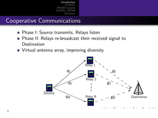
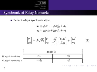
System Model
All channels are Rayleigh flat-fading
Phase I: Source transmits [s1, s2], (differential encoded)
Relays receive [x11, x12] and [x21, x22]
Phase II: Relays re-transmit [x11, x12] and [−x∗
22, x∗
21]
[s1, s2]
[x11, x12]
[−x∗
22, x∗
21]
[y1, y2]
q1
q2
g1
g2Source
Destination
Relay 1
Relay 2
5](https://image.slidesharecdn.com/ucifeb14-150711002130-lva1-app6891/85/Asynchronous-Differential-Distributed-Space-Time-Coding-5-320.jpg)
![Introduction
D-DSTC
OFDM Systems
D-DSTC OFDM
Summary
Frequency Selective Channels
Flat-fading channel, one tap filter h[k] = h0:
y[k] = h0x[k] + n[k]
Frequency selective channel, multiple taps filter:
h[k] =
L−1
l=0
hl δ[k − l]
y[k] = x ∗ h =
L
l=0
hl x[k − l] + n[k]
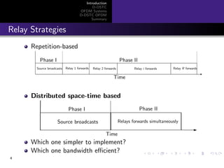
Inter Symbol Interference (ISI)
Orthogonal frequency-division multiplexing (OFDM)
9](https://image.slidesharecdn.com/ucifeb14-150711002130-lva1-app6891/85/Asynchronous-Differential-Distributed-Space-Time-Coding-10-320.jpg)
![Introduction
D-DSTC
OFDM Systems
D-DSTC OFDM
Summary
Point-to-Point OFDM Structure
x = [x1, · · · , xN ], y = [y1, · · · , yN]
yn = Hnxn + nn, n = 1, · · · , N
bits x
ˆx
Add
Remove
Cyclic Prefix
Cyclic Prefix
Modulation
Detection
X Xcp
ISI Channel
YcpYy
DFT
IDFT
Frequency diversity can be achieved by using channel coding
What are drawbacks of OFDM?
10](https://image.slidesharecdn.com/ucifeb14-150711002130-lva1-app6891/85/Asynchronous-Differential-Distributed-Space-Time-Coding-11-320.jpg)
![Introduction
D-DSTC
OFDM Systems
D-DSTC OFDM
Summary
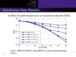
Simulation Results
5 10 15 20 25 30
10
−4
10
−3
10
−2
10
−1
SNR per bit,[dB]
biterrorprobability
Ncp=0
Ncp=2
Ncp=4
Ncp=6
Ncp=8
theory
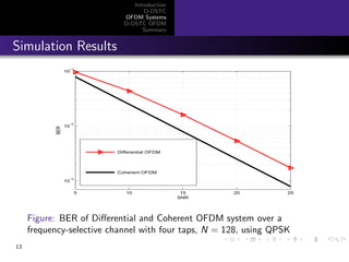
Figure: BER of OFDM system over a frequency-selective channel with
four taps, N = 128, using QPSK for different values of cyclic prefix
11](https://image.slidesharecdn.com/ucifeb14-150711002130-lva1-app6891/85/Asynchronous-Differential-Distributed-Space-Time-Coding-12-320.jpg)
![Introduction
D-DSTC
OFDM Systems
D-DSTC OFDM
Summary
Differential OFDM
v = [v1, · · · , vN ], x(k) = [x1, · · · , xN]
Differential Encoding: x
(k)
n = vnx
(k−1)
n , n = 1, · · · , N
Decoding: y
(k)
n = vny
(k−1)
n + wn, n = 1, · · · , N
Requires constant channel over two OFDM blocks, i.e., 2N
symbols
3 dB performance loss compared with coherent detection
12](https://image.slidesharecdn.com/ucifeb14-150711002130-lva1-app6891/85/Asynchronous-Differential-Distributed-Space-Time-Coding-13-320.jpg)
![Introduction
D-DSTC
OFDM Systems
D-DSTC OFDM
Summary
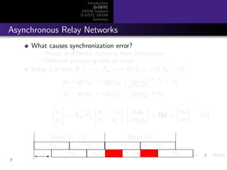
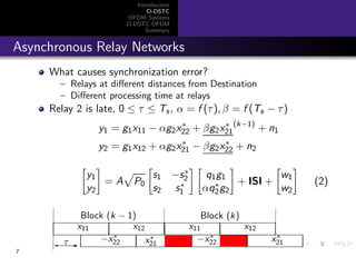
Asynchronous vs. Frequency Selectivity
Relay 2 is late:
y1 = g1x11 − αg2x∗
22 + βg2x∗
21
(k−1)
+ n1
y2 = g1x12 + αg2x∗
21 − βg2x∗
22 + n2
Relay 1-Destination channel: flat-fading, g1
Relay 2-Destination channel: can be assumed as frequency
selective, [αg2, βg2]
What is the difference between [αg2, βg2] and an actual
frequency-selective channel?
Block (k)Block (k − 1)
τ
x11 x12
−x∗
22 x∗
21
x11 x12
−x∗
22 x∗
21
14](https://image.slidesharecdn.com/ucifeb14-150711002130-lva1-app6891/85/Asynchronous-Differential-Distributed-Space-Time-Coding-15-320.jpg)
![Introduction
D-DSTC
OFDM Systems
D-DSTC OFDM
Summary
Differential Distributed Space-Time Coding OFDM
(D-DSTC OFDM)
Data symbols:
v1 = [v1(1), · · · , v1(N)], v2 = [v2(1), · · · , v2(N)]
Construct space-time matrices:
V(k) =
v1(k) −v∗
2 (k)
v2(k) v∗
1 (k)
, k = 1, · · · , N
Encode differentially: s(k) = V(k)s(k−1) =
s
(k)
1
s
(k)
2
Collect symbols:
s1 = [s1(1), · · · , s1(N)], s2 = [s2(1), · · · , s2(N)]
S1 = IDFT(s1), S2 = IDFT(s∗
2)
15](https://image.slidesharecdn.com/ucifeb14-150711002130-lva1-app6891/85/Asynchronous-Differential-Distributed-Space-Time-Coding-16-320.jpg)
![Introduction
D-DSTC
OFDM Systems
D-DSTC OFDM
Summary
D-DSTC OFDM continue
Phase I: Source transmits [S1, S2]
Relays receive [X11, X12] and [X21, X22]
Phase II: Relays re-transmit [X11, ctr(X∗
12)] and
[−X22, ctr(X∗
21)]
[S1, S2]
[X11, ctr(X∗
12)]
[−X22, ctr(X∗
21)]
[Y1, Y2]
q1
q2
g1
g2Source
Destination
Relay 1
Relay 2
16](https://image.slidesharecdn.com/ucifeb14-150711002130-lva1-app6891/85/Asynchronous-Differential-Distributed-Space-Time-Coding-17-320.jpg)
![Introduction
D-DSTC
OFDM Systems
D-DSTC OFDM
Summary
D-DSTC OFDM continue
Circular Time-Reversal: ctr(X) = [X(1), X(N), · · · , X(2)]
x
IDFT
−−−→ X
∗
−→ X∗ ctr
−→ ˜X
DFT
−−−→ x∗
At Destination: Remove Cyclic Prefix, apply DFT
y1 = [y1(1), · · · , y1(N)], y2 = [y2(1), · · · , y2(N)]
y(k)
=
y1(k)
y2(k)
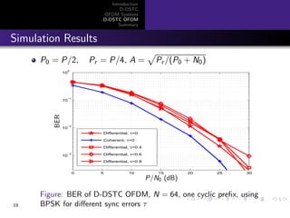
= A P0
s1(k) −s∗
2 (k)
s2(k) s∗
1 (k)
H1
H2
+
W1
W2
,
k = 1, · · · , N
Differential decoding: y(k) = V(k)y(k−1) + ˜w(k)
17](https://image.slidesharecdn.com/ucifeb14-150711002130-lva1-app6891/85/Asynchronous-Differential-Distributed-Space-Time-Coding-18-320.jpg)


![RF Module Design - [Chapter 1] From Basics to RF Transceivers](https://cdn.slidesharecdn.com/ss_thumbnails/rfch1-150613070344-lva1-app6892-thumbnail.jpg?width=640&height=640&fit=bounds)

![射頻電子實驗手冊 [實驗6] 阻抗匹配模擬](https://cdn.slidesharecdn.com/ss_thumbnails/simlab6-150613072411-lva1-app6892-thumbnail.jpg?width=640&height=640&fit=bounds)
![RF Module Design - [Chapter 3] Linearity](https://cdn.slidesharecdn.com/ss_thumbnails/rfch3-150613070345-lva1-app6891-thumbnail.jpg?width=640&height=640&fit=bounds)

![射頻電子 - [第四章] 散射參數網路](https://cdn.slidesharecdn.com/ss_thumbnails/ch4-150613065103-lva1-app6891-thumbnail.jpg?width=640&height=640&fit=bounds)


![射頻電子 - [第一章] 知識回顧與通訊系統簡介](https://cdn.slidesharecdn.com/ss_thumbnails/ch1-150613065058-lva1-app6891-thumbnail.jpg?width=640&height=640&fit=bounds)


![電路學 - [第三章] 網路定理](https://cdn.slidesharecdn.com/ss_thumbnails/circuitch3-150613063007-lva1-app6892-thumbnail.jpg?width=640&height=640&fit=bounds)


![電路學 - [第五章] 一階RC/RL電路](https://cdn.slidesharecdn.com/ss_thumbnails/circuitch5-150613063008-lva1-app6891-thumbnail.jpg?width=640&height=640&fit=bounds)


