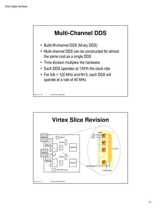
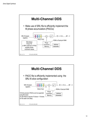
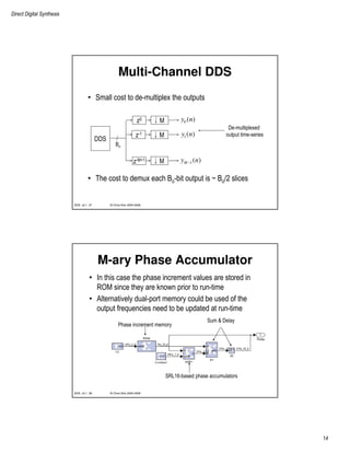
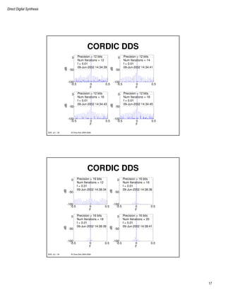
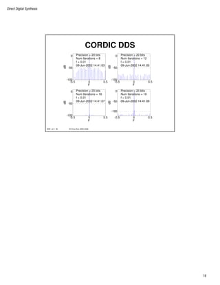
This document discusses direct digital synthesis (DDS) techniques. DDS allows digitally generating waveforms by mapping a phase increment to sinusoidal outputs. Key aspects covered include: phase truncation DDS using lookup tables, dithered DDS to reduce spurs, and Taylor series expansion DDS for higher precision. Applications include digital up/down converters. Multi-channel DDS can efficiently generate multiple signals using time division multiplexing of hardware.

![Direct Digital Synthesis
4
© Chris Dick 2004-2009DDS v2.1 7
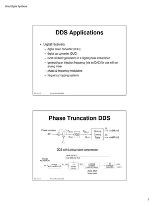
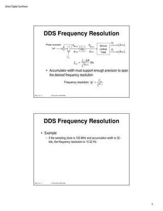
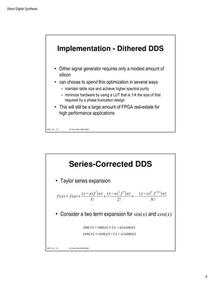
Phase Truncation DDS
0 0.1 0.2 0.3 0.4 0.5
-100
-80
-60
-40
-20
0
NORMALIZED FREQUENCY
DB
PHASE
INCREMENT
∆φ M
clk
PHASE
ACCUMULATOR
(e.g. 28-32 bits)
fout = ∆φ fclk/2N
SINE/COSINE
LOOKUP
TABLE
e.g. N = 8-16
θ(n)^
θ(n)
Q( )
N sin(θ(n))
^
cos(θ(n))^
B
B
0 20 40 60 80 100
0
0.5
1
TIME
ERROR
20 40 60 80 100
-1
0
1
TIME
AMPLITUDE
© Chris Dick 2004-2009DDS v2.1 8
DDS Noise
• The term contributing to the DDS noise
component can be calculated by examining the
effect of the phase accumulator quantizer
ˆ( ) [ ( ) ( )] ( ) ( )
ˆ( ) ( )
( ) ( )
ˆ( ) ( ) ( )
[1 ( )]
( )
DESIRED COMPONENT
UNDESIRED COMPONENT
j n j n n j n j n
j n j n
j n j n
n n n
e e e e
e e j n
e j n e
θ θ δθ θ δθ
θ θ
θ θ
θ θ δθ
δθ
δθ
+
= +
= =
≈ +
= +](https://image.slidesharecdn.com/dds2-171227113639/85/Dds-2-4-320.jpg)
![Direct Digital Synthesis
15
© Chris Dick 2004-2009DDS v2.1 29
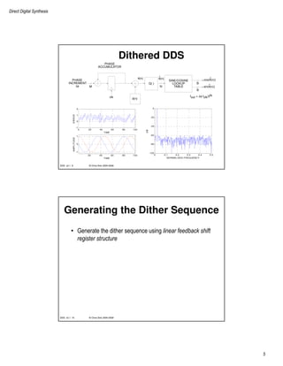
M-ary Taylor Series DDS
Channel demultiplexing
M-ary phase accumulator
DDS
© Chris Dick 2004-2009DDS v2.1 30
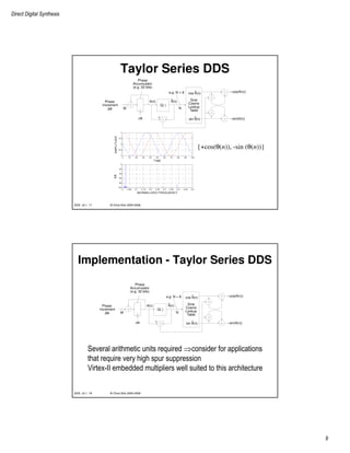
3-Channel Taylor Series DDS
-0.5 0 0.5
-140
-120
-100
-80
-60
-40
-20
0
Frequency
DB
LUT Depth = 4096
LUT Precision = 18
Output Precision = 20
f = [0.1, 0.2, 0.3]
09-Jun-2002 11:37:14
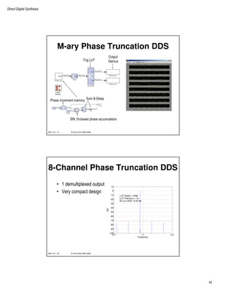
• 3 tones efficiently generated
by time sharing the hardware
• Sample-rate versus area
tradeoff](https://image.slidesharecdn.com/dds2-171227113639/85/Dds-2-15-320.jpg)
![射頻電子實驗手冊 [實驗6] 阻抗匹配模擬](https://cdn.slidesharecdn.com/ss_thumbnails/simlab6-150613072411-lva1-app6892-thumbnail.jpg?width=640&height=640&fit=bounds)
![RF Module Design - [Chapter 1] From Basics to RF Transceivers](https://cdn.slidesharecdn.com/ss_thumbnails/rfch1-150613070344-lva1-app6892-thumbnail.jpg?width=640&height=640&fit=bounds)


![射頻電子 - [第一章] 知識回顧與通訊系統簡介](https://cdn.slidesharecdn.com/ss_thumbnails/ch1-150613065058-lva1-app6891-thumbnail.jpg?width=640&height=640&fit=bounds)


![Multiband Transceivers - [Chapter 1]](https://cdn.slidesharecdn.com/ss_thumbnails/ch1-150613070932-lva1-app6891-thumbnail.jpg?width=640&height=640&fit=bounds)
![RF Module Design - [Chapter 8] Phase-Locked Loops](https://cdn.slidesharecdn.com/ss_thumbnails/rfch8-150613070348-lva1-app6892-thumbnail.jpg?width=640&height=640&fit=bounds)


![RF Module Design - [Chapter 3] Linearity](https://cdn.slidesharecdn.com/ss_thumbnails/rfch3-150613070345-lva1-app6891-thumbnail.jpg?width=640&height=640&fit=bounds)

![RF Circuit Design - [Ch2-1] Resonator and Impedance Matching](https://cdn.slidesharecdn.com/ss_thumbnails/ch2-1-150613064353-lva1-app6892-thumbnail.jpg?width=640&height=640&fit=bounds)