Downloaded 25 times
![Antenna Engineering, Peter Knott Tutorial Patch Antenna Design
Patch Antenna Design using MICROWAVE STUDIO
1 What is CST MICROWAVE STUDIO ?
CST MICROWAVE STUDIO is a full-featured software package for electromagnetic anal-
ysis and design in the high frequency range. It simplifies the process of inputting the struc-
ture by providing a powerful solid 3D modelling front end, see figure ??. Strong graphic
feedback simplifies the definition of your device even further. After the component has
been modelled, a fully automatic meshing procedure is applied before a simulation engine
is started.
CST MICROWAVE STUDIO is part of the CST DESIGN STUDIO suite [?] and offers
a number of different solvers for different types of application. Since no method works
equally well in all application domains, the software contains four different simulation
techniques (transient solver, frequency domain solver, integral equation solver, eigenmode
solver) to best fit their particular applications.
The most flexible tool is the transient solver, which can obtain the entire broadband
frequency behaviour of the simulated device from only one calculation run (in contrast
to the frequency step approach of many other simulators). It is based on the Finite
Integration Technique (FIT) introduced in electrodynamics more than three decades ago
[?]. This solver is efficient for most kinds of high frequency applications such as connectors,
transmission lines, filters, antennas and more. In this tutorial we will make use of the
transient solver for designing a microstrip patch antenna as an example.
Figure 3: Graphical User Interface of CST MICROWAVE STUDIO
version 02/01/10 p. 11](https://image.slidesharecdn.com/tutorial2-160721002327/85/Tutorial-2-1-320.jpg)
![Antenna Engineering, Peter Knott Tutorial Patch Antenna Design
Patch Antenna Design using MICROWAVE STUDIO
1 What is CST MICROWAVE STUDIO ?
CST MICROWAVE STUDIO is a full-featured software package for electromagnetic anal-
ysis and design in the high frequency range. It simplifies the process of inputting the struc-
ture by providing a powerful solid 3D modelling front end, see figure ??. Strong graphic
feedback simplifies the definition of your device even further. After the component has
been modelled, a fully automatic meshing procedure is applied before a simulation engine
is started.
CST MICROWAVE STUDIO is part of the CST DESIGN STUDIO suite [?] and offers
a number of different solvers for different types of application. Since no method works
equally well in all application domains, the software contains four different simulation
techniques (transient solver, frequency domain solver, integral equation solver, eigenmode
solver) to best fit their particular applications.
The most flexible tool is the transient solver, which can obtain the entire broadband
frequency behaviour of the simulated device from only one calculation run (in contrast
to the frequency step approach of many other simulators). It is based on the Finite
Integration Technique (FIT) introduced in electrodynamics more than three decades ago
[?]. This solver is efficient for most kinds of high frequency applications such as connectors,
transmission lines, filters, antennas and more. In this tutorial we will make use of the
transient solver for designing a microstrip patch antenna as an example.
Figure 3: Graphical User Interface of CST MICROWAVE STUDIO
version 02/01/10 p. 11](https://image.slidesharecdn.com/tutorial2-160721002327/75/Tutorial-2-1-2048.jpg)
![Antenna Engineering, Peter Knott Tutorial Patch Antenna Design
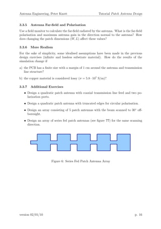
Figure 4: Typical Patch Antenna Geometry and Dimensions
β at the central frequency. Additionally, the port impedance is calculated automatically
(line impedance).
3.2 Analyse S-Parameters and Field Quantities
At the end of a successful simulation run you may also retrieve the other output data
from the navigation tree, e.g. S-Parameters and electromagnetic field quantities.
References
[1] Computer Simulation Technology (CST), “CST Design Studio”,
http://www.cst.com/Content/Products/DS/Overview.aspx
[2] T. Weiland, “ Discretization Method for the Solution of Maxwell’s Equations for
Six-Component Fields”, Electron. Commun. (AE¨U), Vol. 31, No. 3, pp. 116-120,
1977
3.3 Exercises
3.3.1 Rectangular Patch Antenna for WLAN application
The aim of this tutorial is the design of a microstrip patch antenna for a practical Wireless
Local Area Network (WLAN) application operating at 2.4 GHz as well as connecting and
matching the antenna to the system via a microstrip transmission line. The typical
geometry of a patch antenna and the dimension parameters important for specifying a
design are shown in figure ??.
version 02/01/10 p. 14](https://image.slidesharecdn.com/tutorial2-160721002327/85/Tutorial-2-4-320.jpg)

CST Microwave Studio is electromagnetic simulation software that uses the Finite Integration Technique to model high frequency devices. It has several solvers including a transient solver. The document describes the basic workflow for simulating a microstrip patch antenna in CST Microwave Studio, including defining units, materials, geometry, ports, frequencies, and monitors. It then provides exercises to simulate a basic patch antenna at 2.4 GHz and improve its matching bandwidth, examine its far-field pattern, and make the model more realistic.


![High_Frequency_Structure_Simulator_HFSS[1].pdf](https://cdn.slidesharecdn.com/ss_thumbnails/highfrequencystructuresimulatorhfss1-250707201635-2208bc58-thumbnail.jpg?width=640&height=640&fit=bounds)


