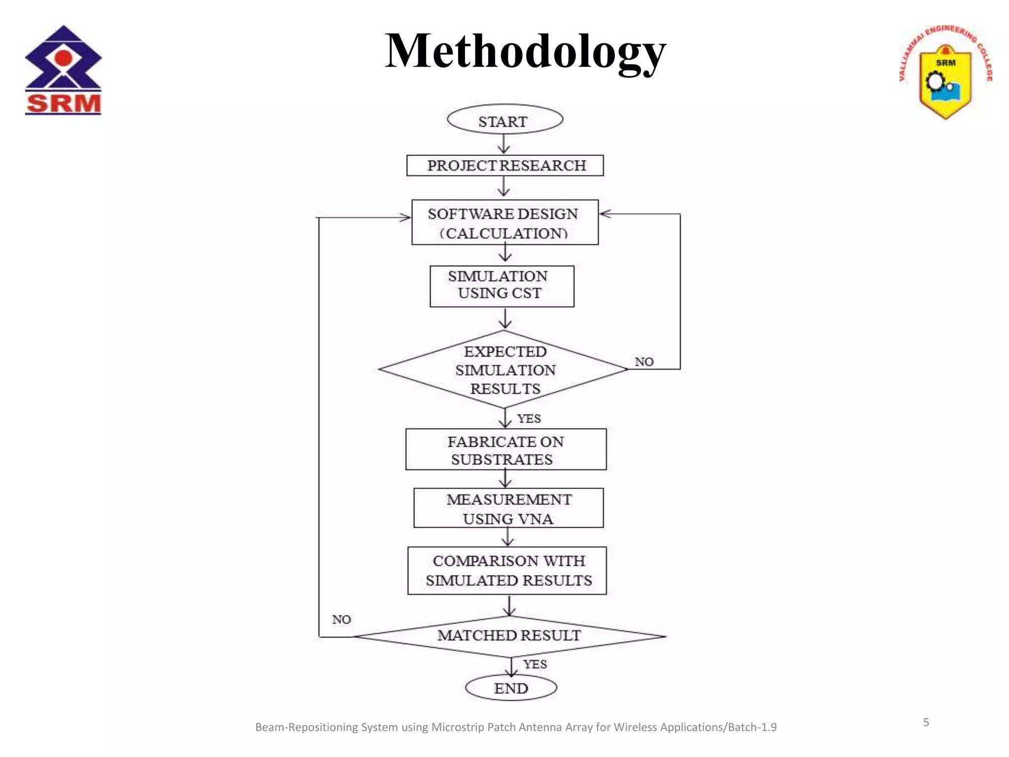
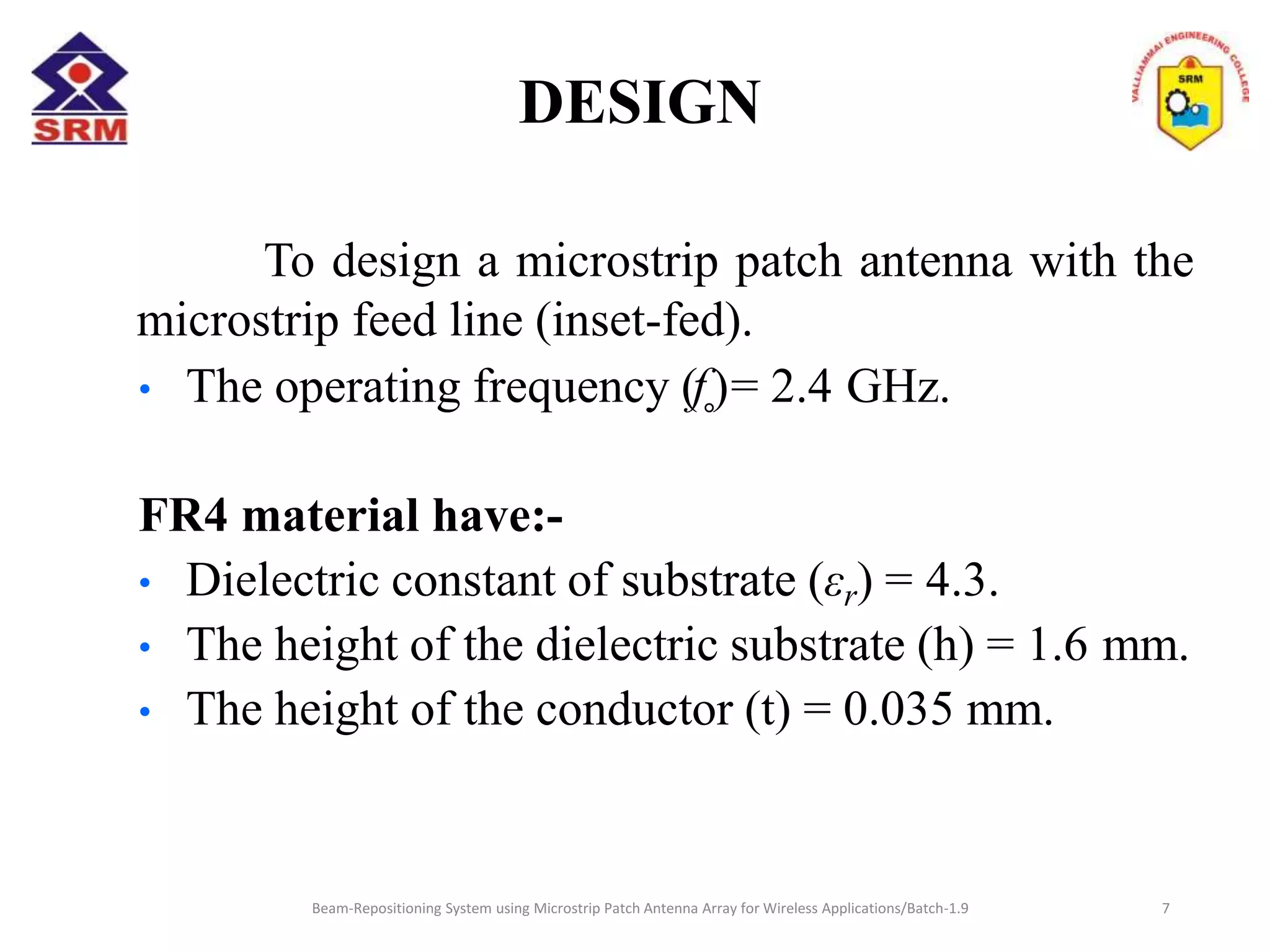
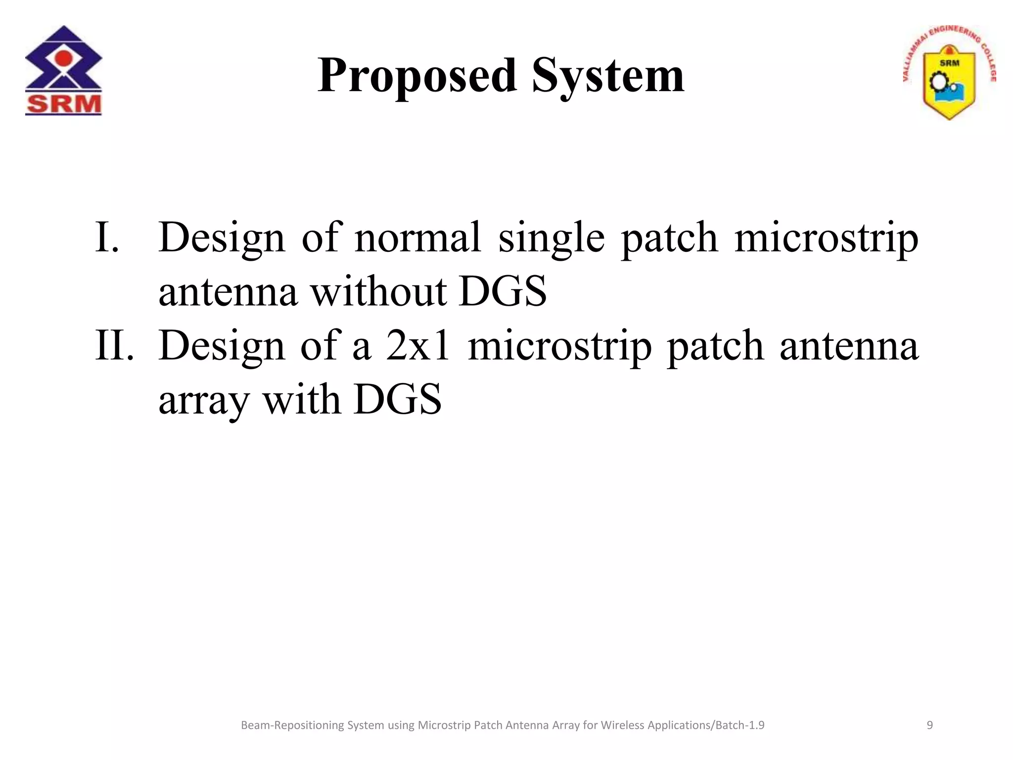
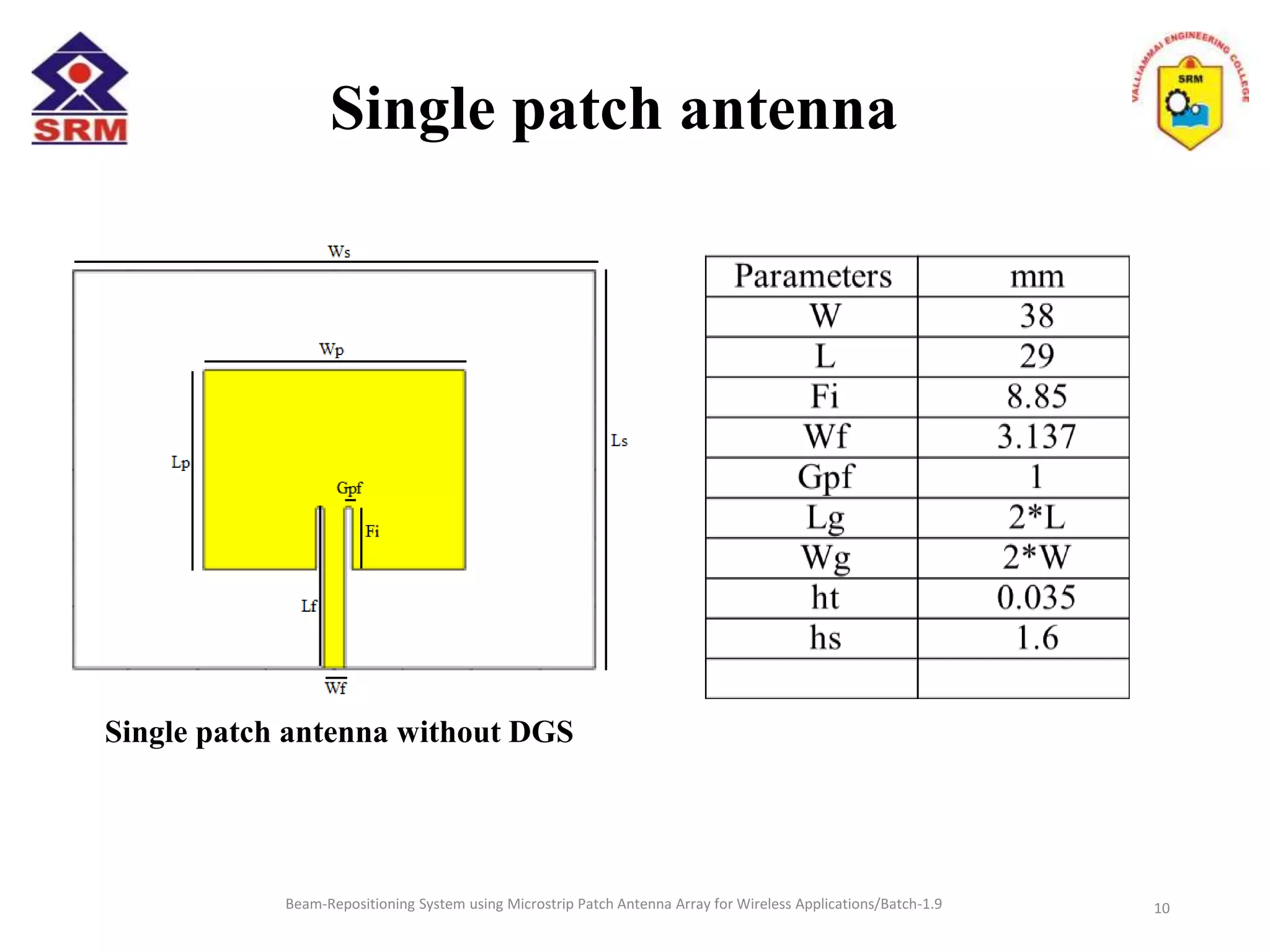
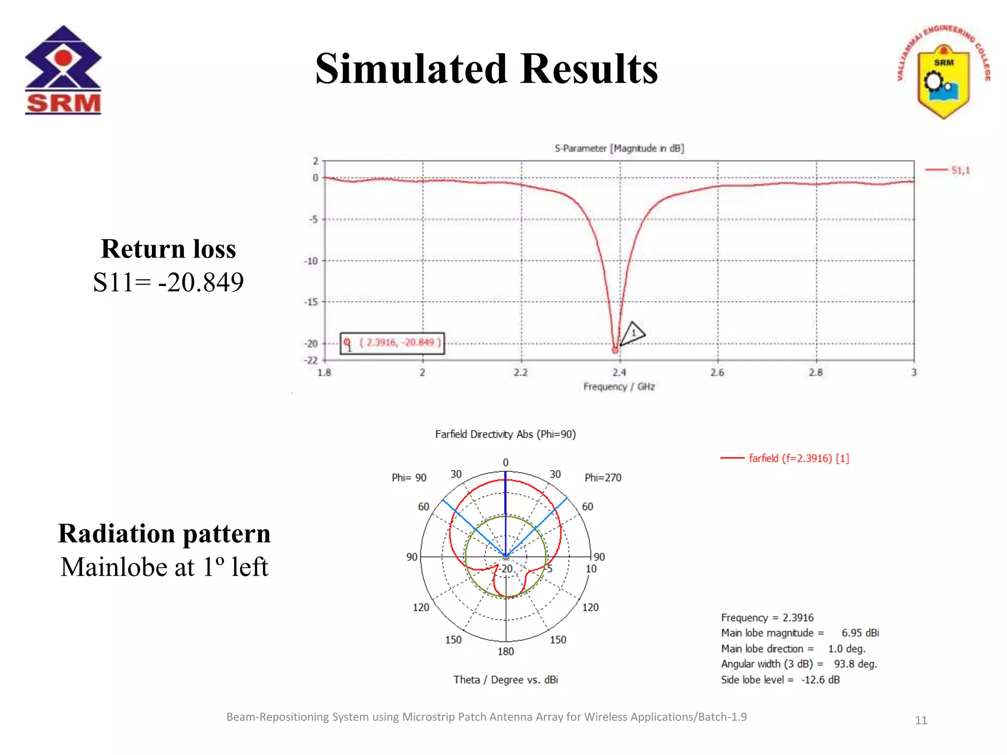
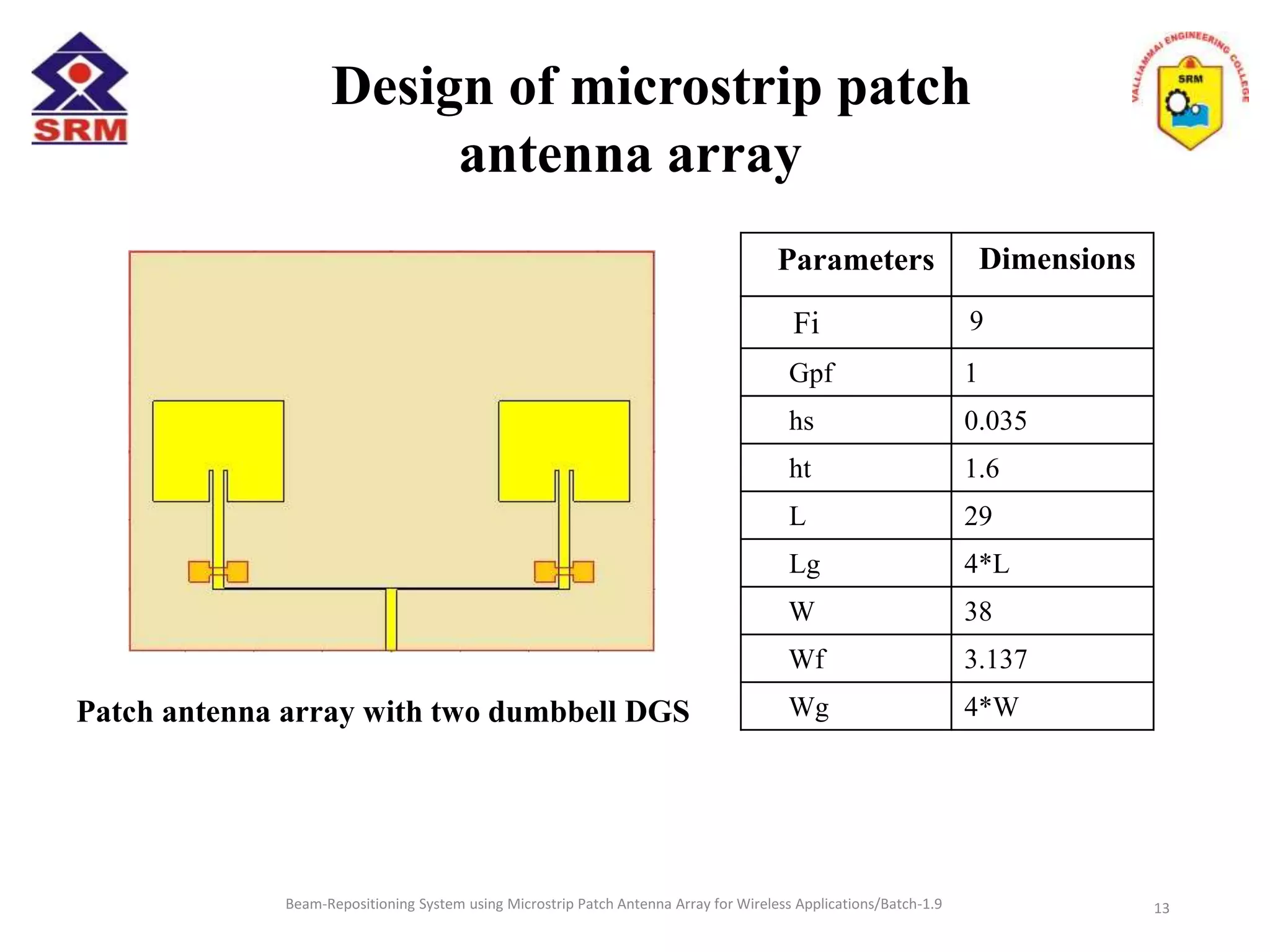
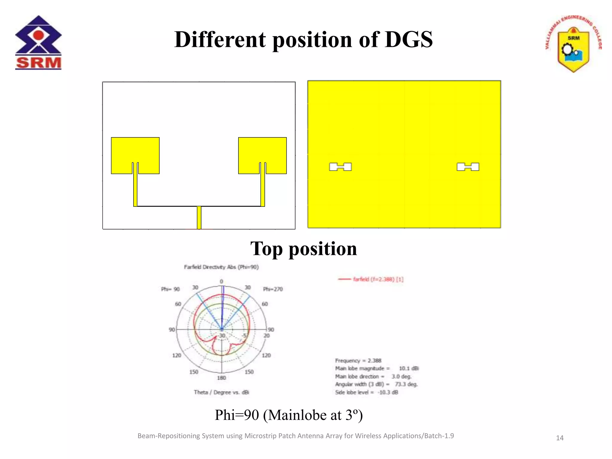
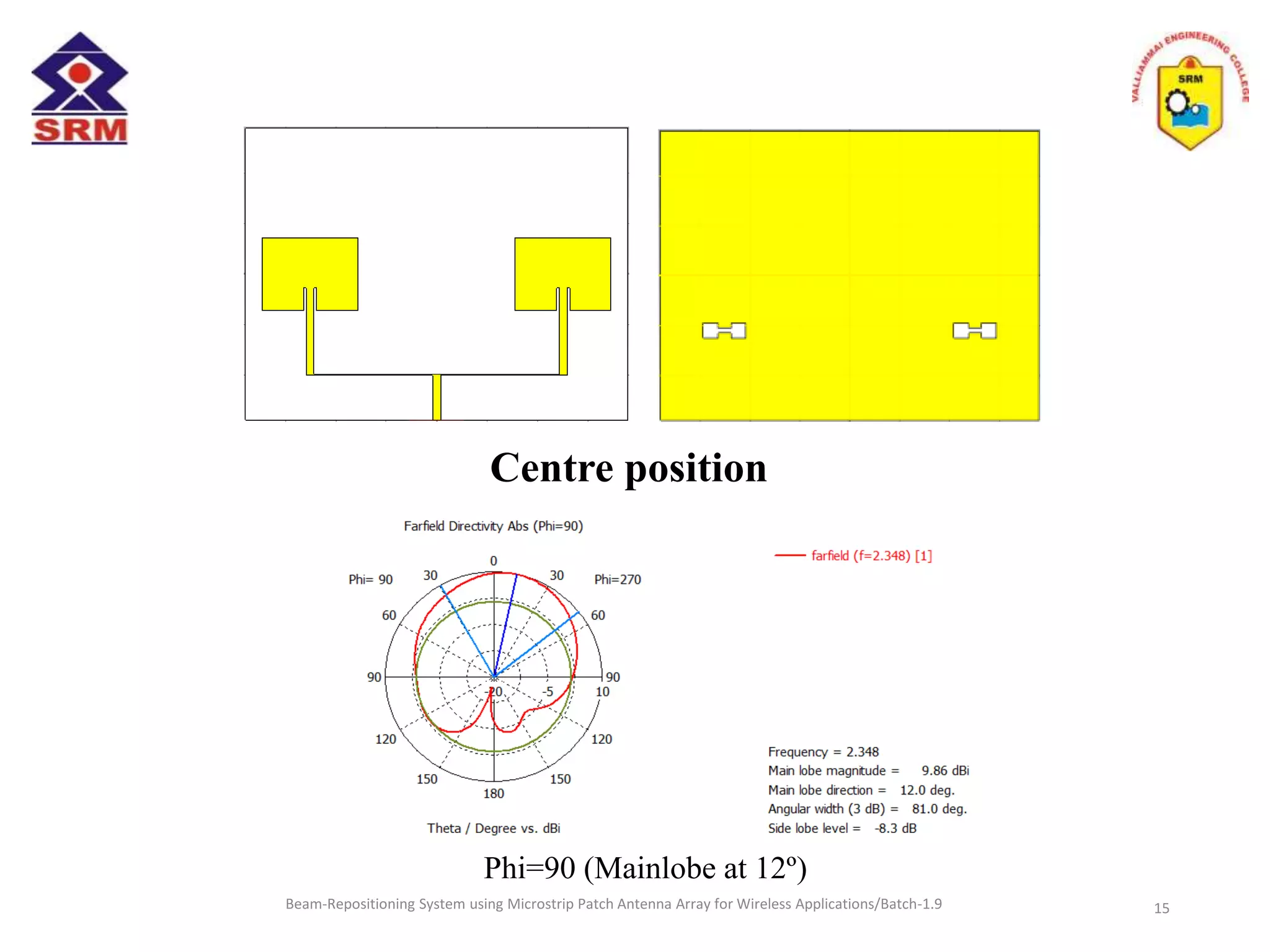
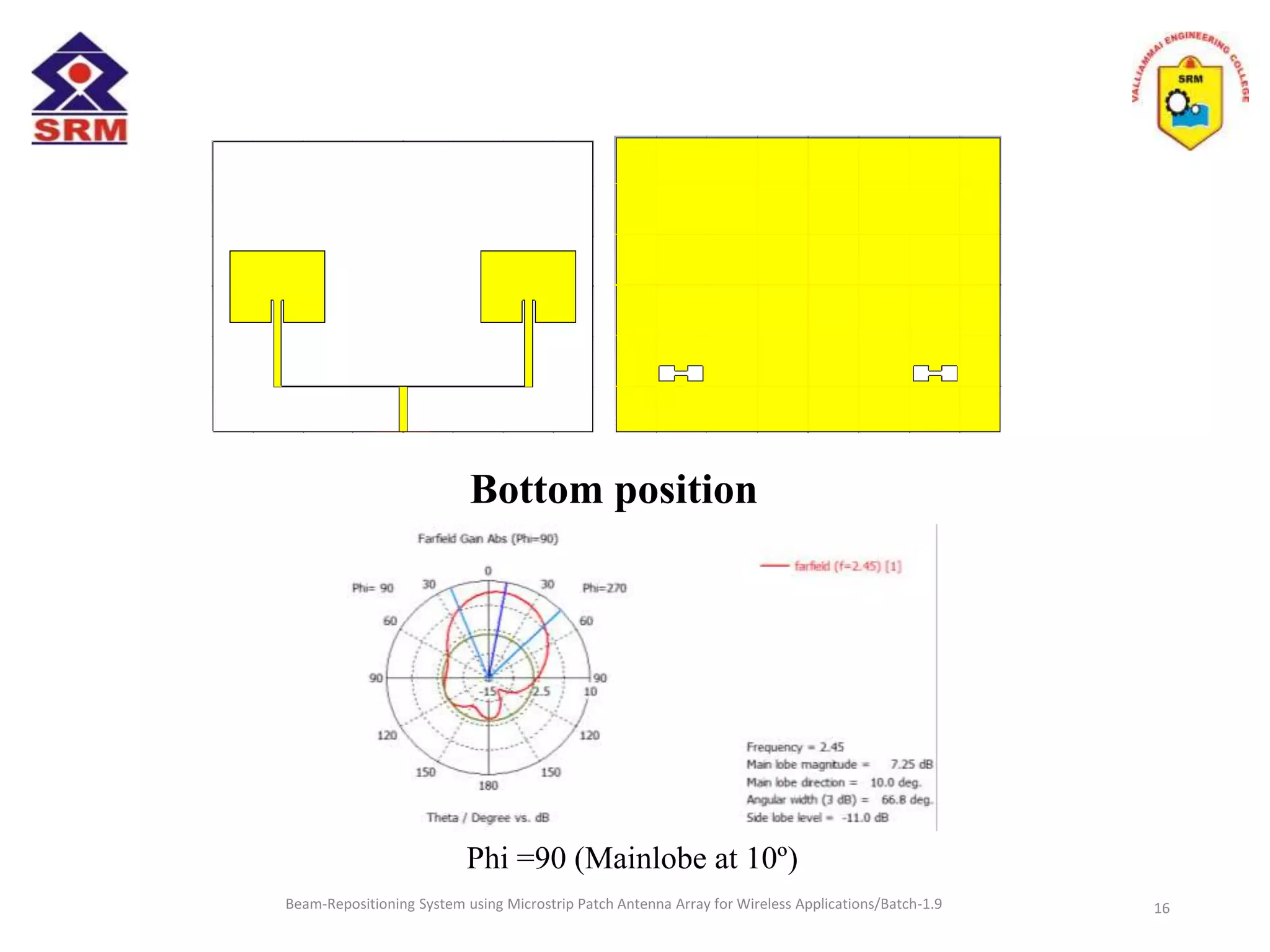
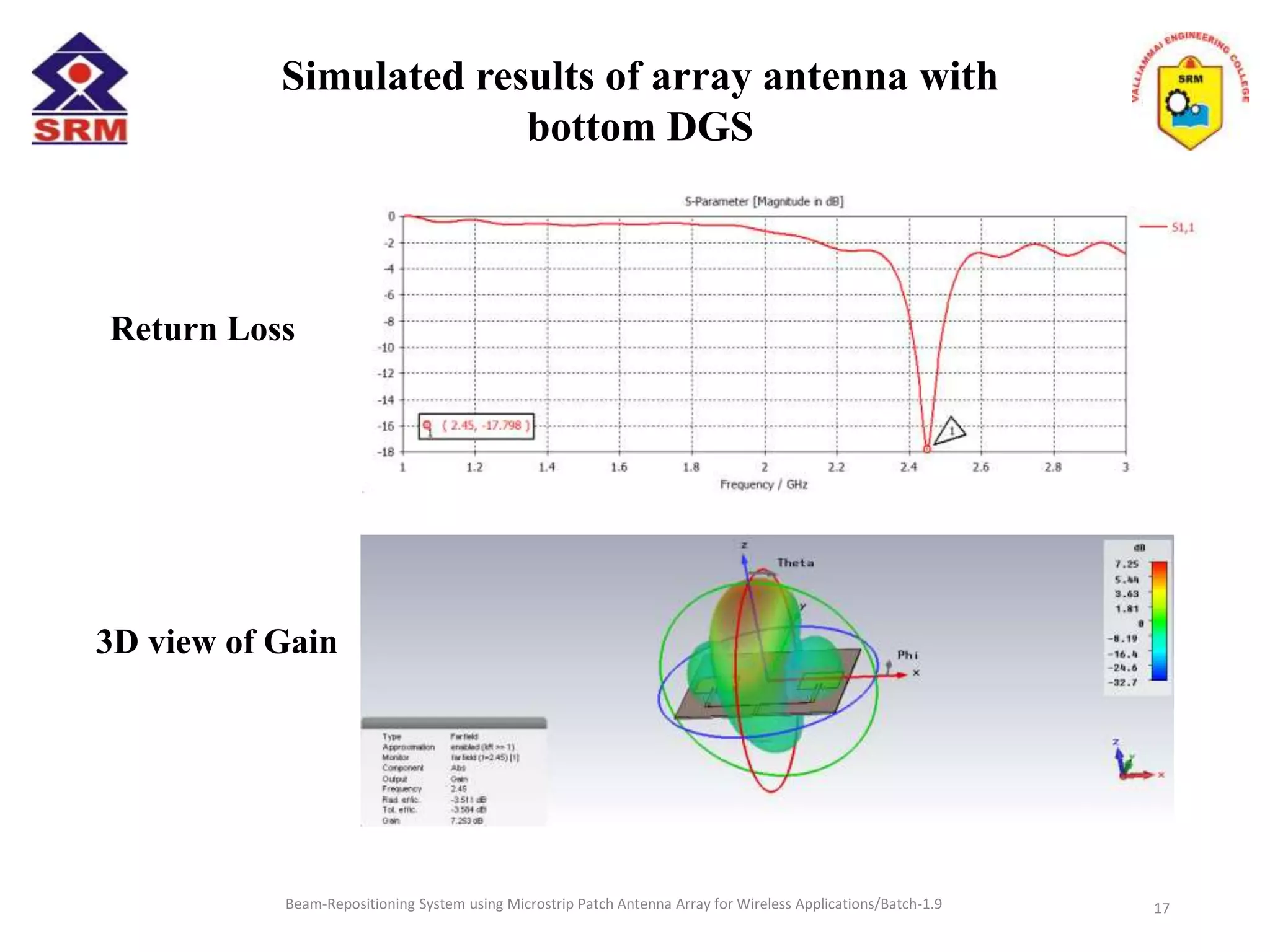
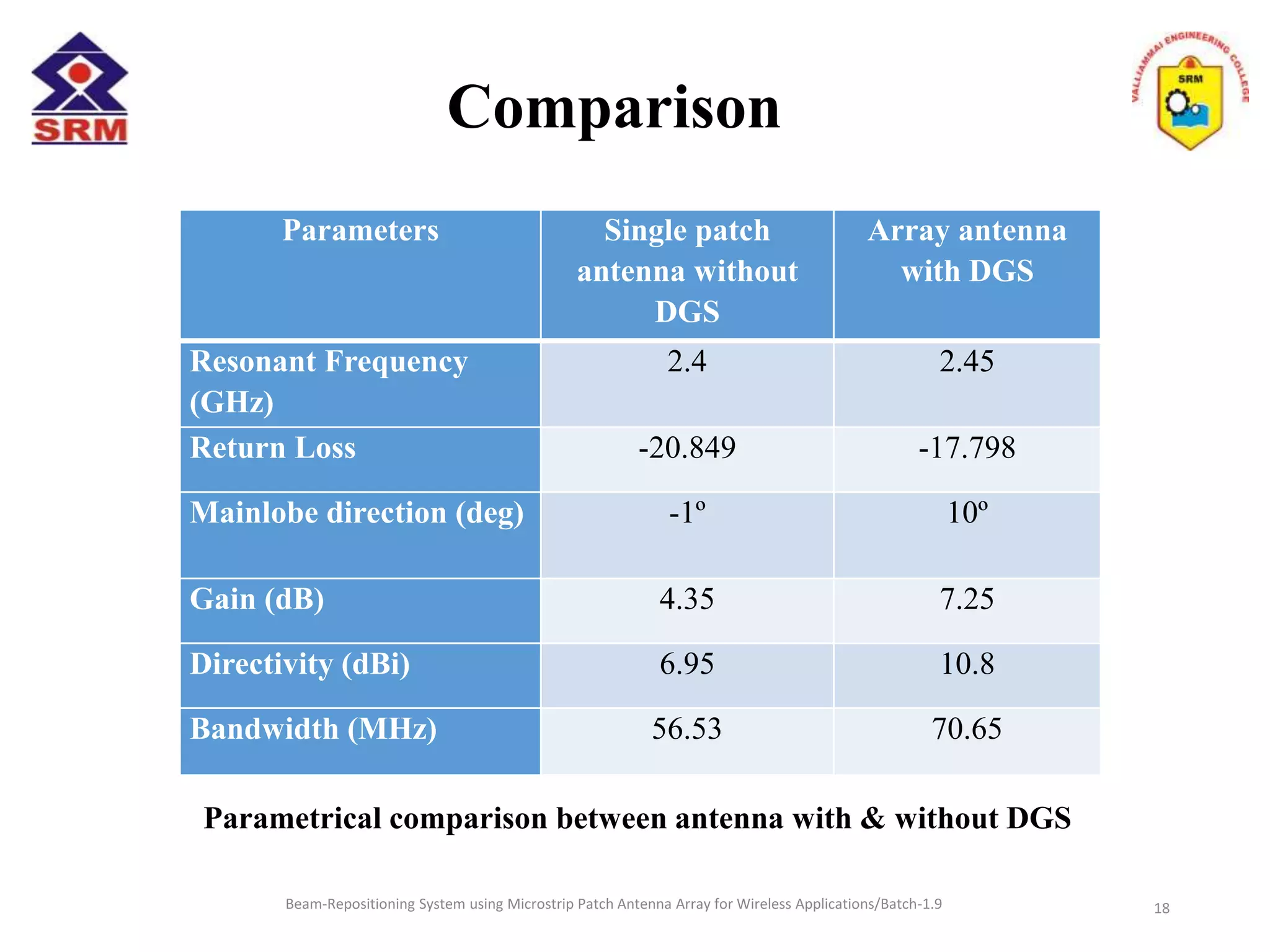
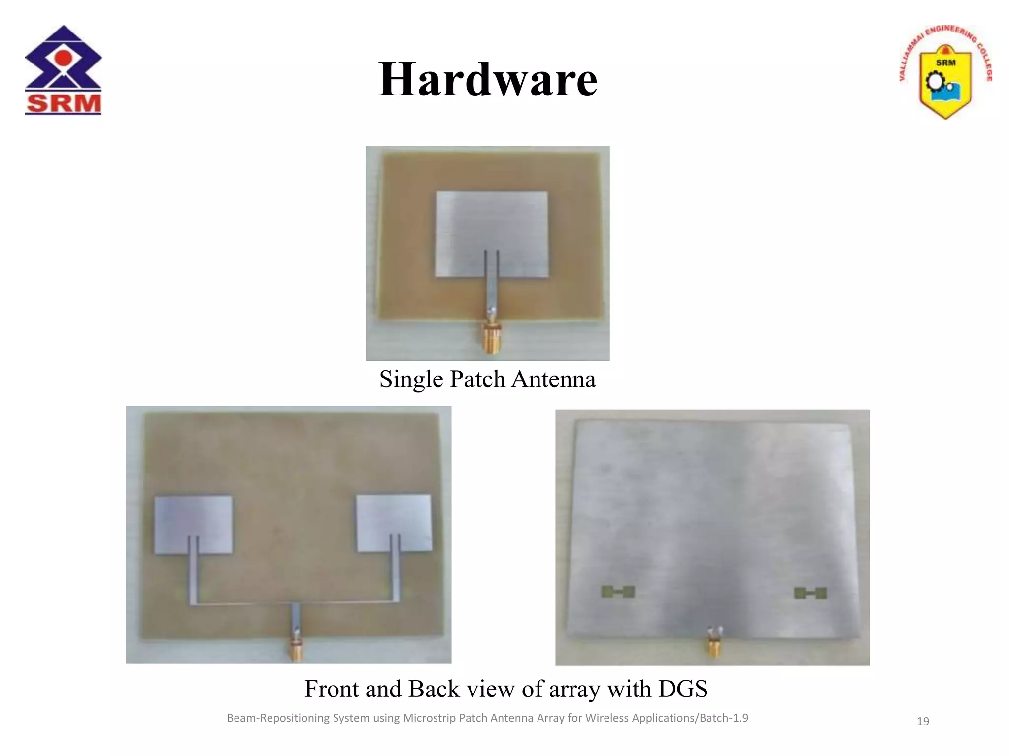
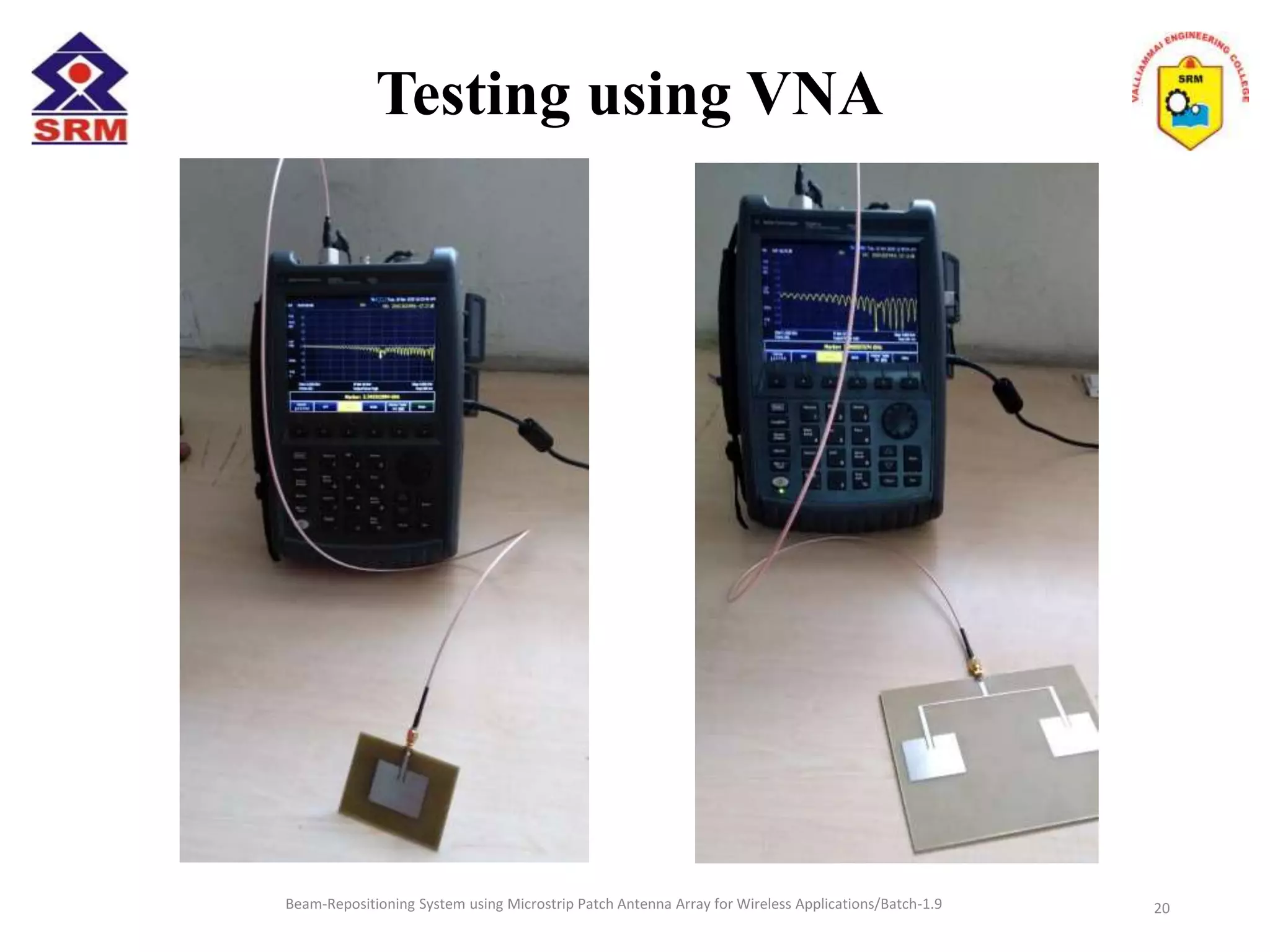
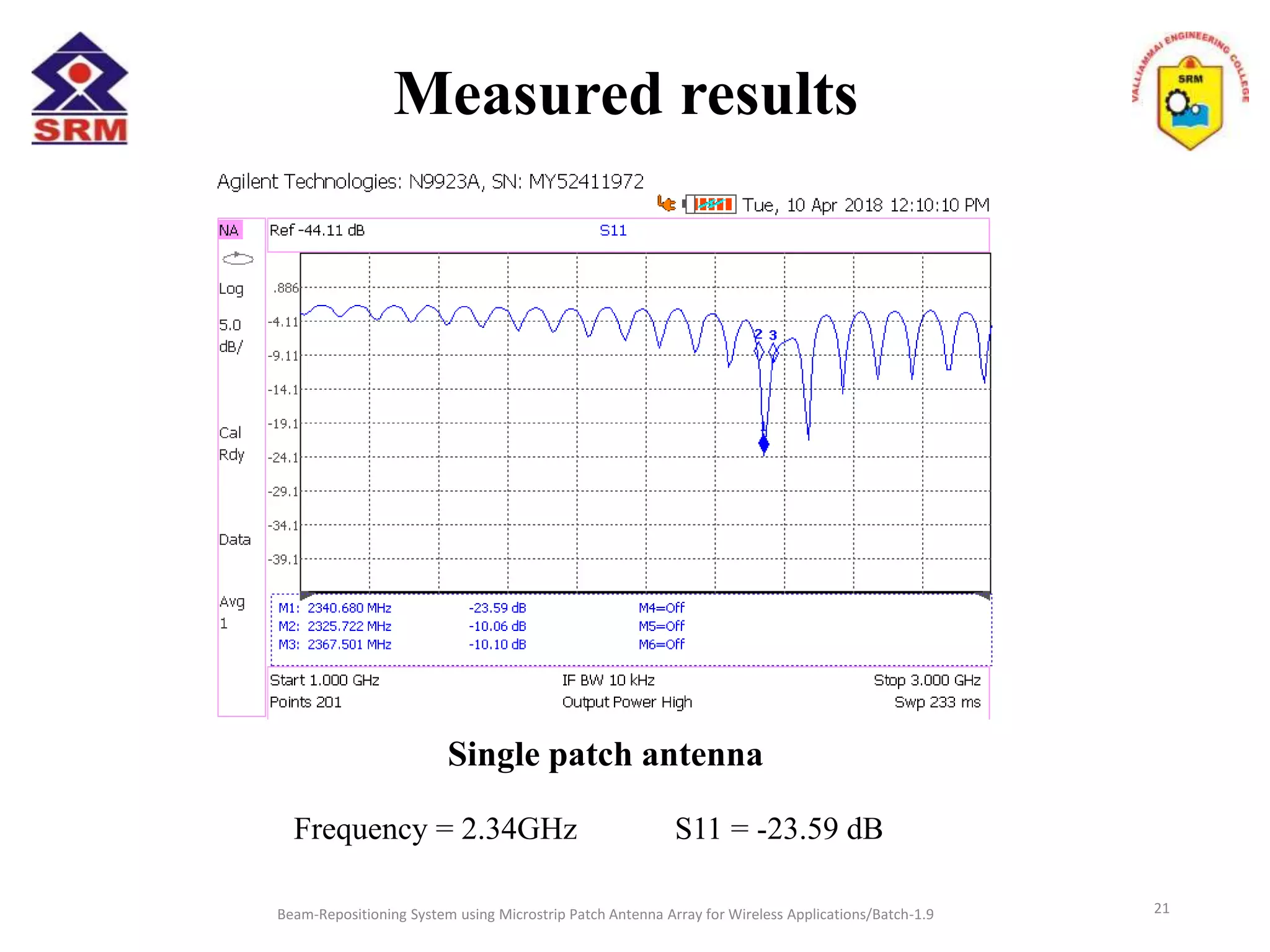
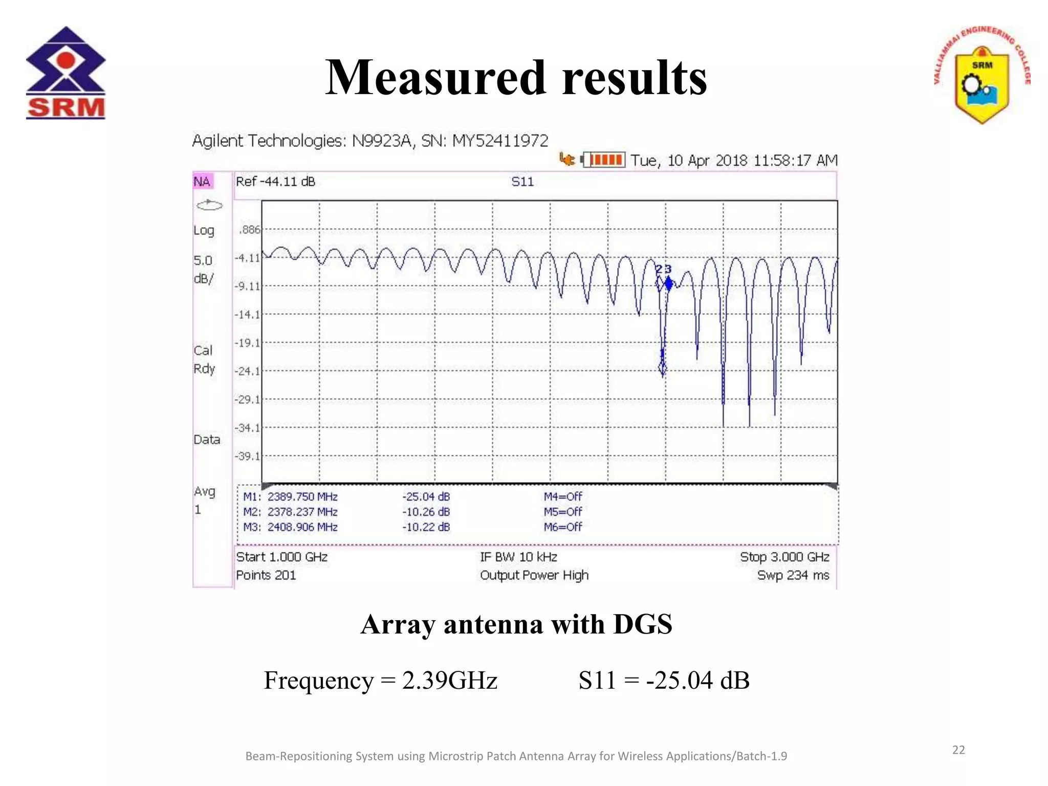
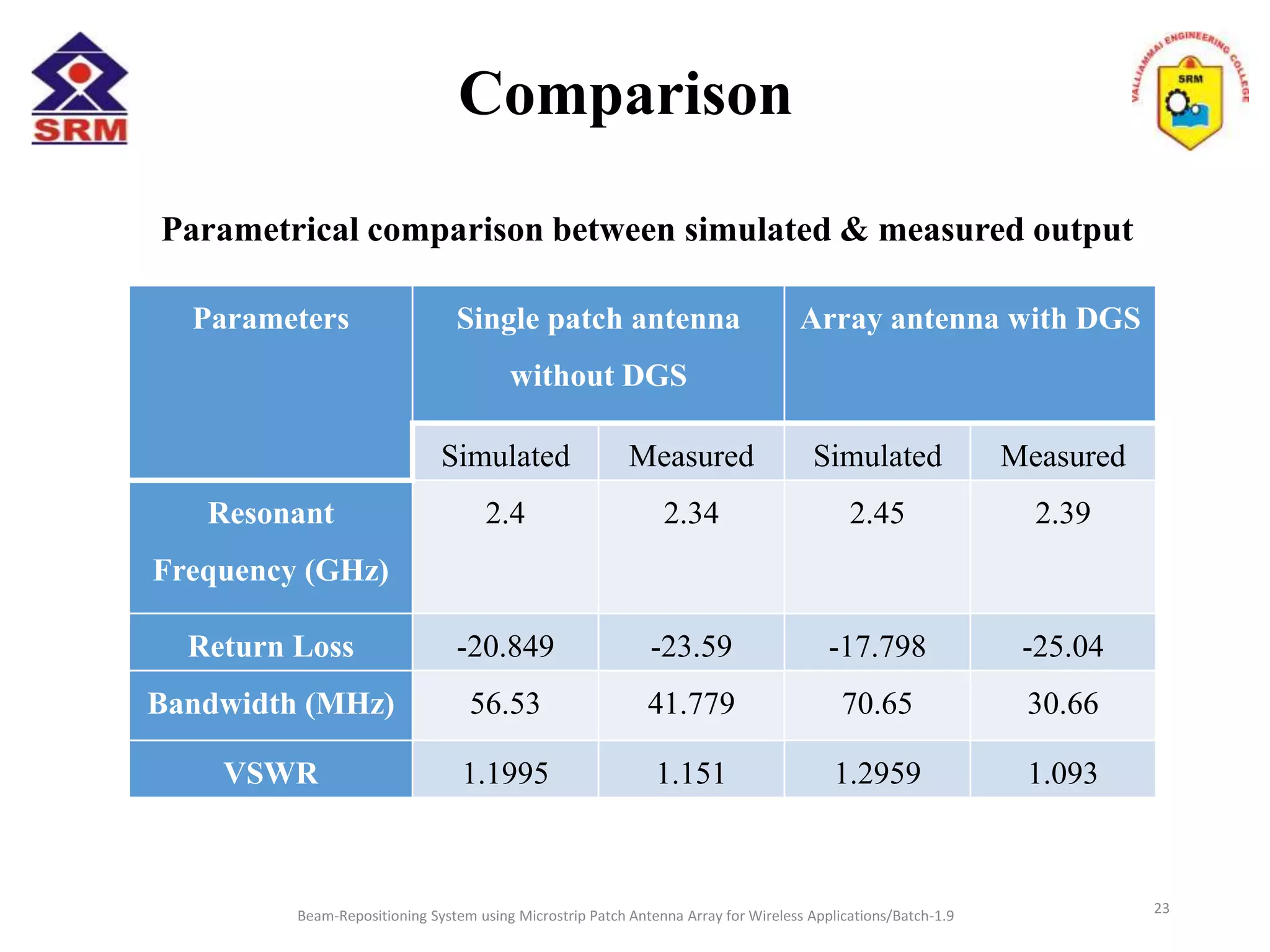
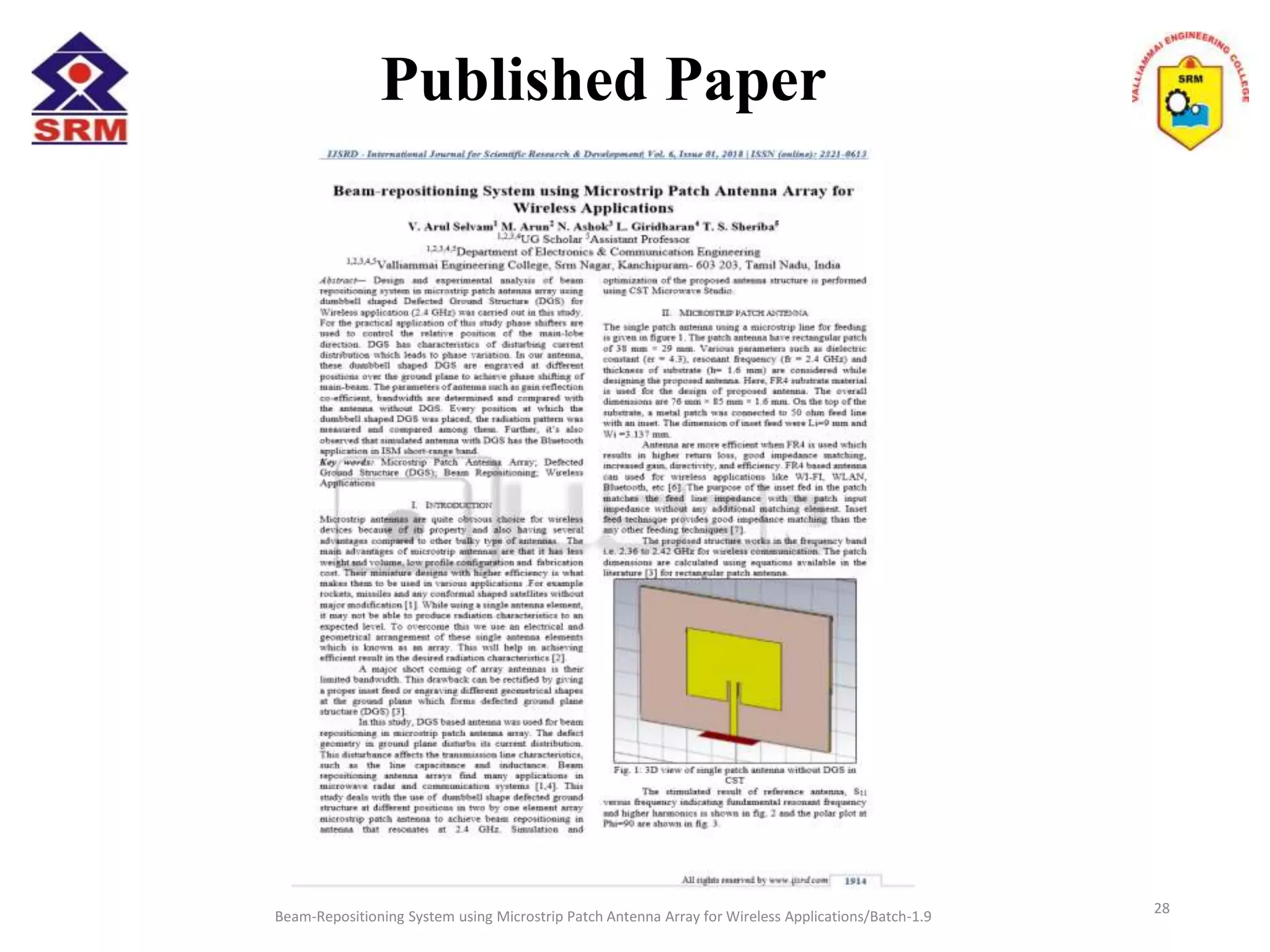
BEAM-REPOSITIONING SYSTEM USING
MICROSTRIP PATCH ARRAY FOR WIRELESS
APPLICATIONS
VALLIAMMAI ENGINEERING COLLEGE
SRM Nagar, Kattankulathur – 603 203.
Department of Electronics & Communication Engineering
Presented by
Arul Selvam V - 412814106014
Arun M - 412814106015
Ashok N - 412814106021
Giridharan L - 412814106048
Under the guidance of
Ms.T.S.Sheriba, M.Tech, (Ph.D),
ASSISTANT PROFESSOR/ECE
Beam-Repositioning System using Microstrip Patch Antenna Array for Wireless Applications/Batch-1.9 1
Overview
• Introduction
• Objective
• Methodology
• Beam-repositioning
• Design
• Proposed System
• Simulated Results
• Different position of
DGS
Beam-Repositioning System using Microstrip Patch Antenna Array for Wireless Applications/Batch-1.9
• Hardware
• Testing
• Measured Results
• Comparison
• Applications
• Conclusion
• Future Work
• Publication Details
• References
2
Introduction
• Microstrip antennas are a definite choice for
wireless devices because of its low fabrication cost,
less weight and profile configurations.
• Array structure is used to overcome the drawback
of single patch antenna in radiation characteristics.
• The design of antenna is simulated using CST
software.
Beam-Repositioning System using Microstrip Patch Antenna Array for Wireless Applications/Batch-1.9 3
Objective
• To operate the antenna at WLAN frequency
(2.4GHz).
• To obtain the minimum return loss (S11< -10dB)
• To steer the direction of the main lobe beam in left
and right positions.
• To simulate and fabricate the microstrip patch
antenna with and without DGS
Beam-Repositioning System using Microstrip Patch Antenna Array for Wireless Applications/Batch-1.9 4
Methodology
Beam-Repositioning System using Microstrip Patch Antenna Array for Wireless Applications/Batch-1.9 5
Beam-Repositioning System
Beam-Repositioning System using Microstrip Patch Antenna Array for Wireless Applications/Batch-1.9 6
Beam repositioning or steering is about changing the
direction of the main lobe of a radiation pattern.
• Adaptive beam steering- dynamically changes the beam
direction
• Static beam steering- permanent main beam direction is
setup whenever it is necessary to accelerate the direction.
DESIGN
Beam-Repositioning System using Microstrip Patch Antenna Array for Wireless Applications/Batch-1.9
To design a microstrip patch antenna with the
microstrip feed line (inset-fed).
• The operating frequency (f˳)= 2.4 GHz.
FR4 material have:-
• Dielectric constant of substrate (εr) = 4.3.
• The height of the dielectric substrate (h) = 1.6 mm.
• The height of the conductor (t) = 0.035 mm.
7
 To Find Width (W)
 To find the effective dielectric constant
 To find the effective length
 To find the fringing length (∆L)
 To find the actual length L & width and length of the Ground
 The input impedance is usually 50 Ω.
 The gap between the patch and the inset-fed is usually 1 mm (Gpf =1).
 The length of inset (Fi)
=2 W=2 L
Beam-Repositioning System using Microstrip Patch Antenna Array for Wireless Applications/Batch-1.9
DESIGN EQUATIONS
8
Proposed System
I. Design of normal single patch microstrip
antenna without DGS
II. Design of a 2x1 microstrip patch antenna
array with DGS
Beam-Repositioning System using Microstrip Patch Antenna Array for Wireless Applications/Batch-1.9 9
Single patch antenna
Beam-Repositioning System using Microstrip Patch Antenna Array for Wireless Applications/Batch-1.9 10
Single patch antenna without DGS
Simulated Results
Beam-Repositioning System using Microstrip Patch Antenna Array for Wireless Applications/Batch-1.9
Return loss
S11= -20.849
Radiation pattern
Mainlobe at 1º left
11
Defected Ground Structure
Beam-Repositioning System using Microstrip Patch Antenna Array for Wireless Applications/Batch-1.9 12
• The compact geometrical slots embedded on the ground plane
of microwave circuits (i.e. microstrip antenna)
• The defects on the ground plane disturb the current
distribution of the ground plane; this disturbance changes the
antenna parameters
• DGS based phase shifter is used for beam steering in
microstrip antenna which results in phase variation.
Dumbbell shape DGS
Beam-Repositioning System using Microstrip Patch Antenna Array for Wireless Applications/Batch-1.9
Design of microstrip patch
antenna array
Parameters Dimensions
Fi 9
Gpf 1
hs 0.035
ht 1.6
L 29
Lg 4*L
W 38
Wf 3.137
Wg 4*WPatch antenna array with two dumbbell DGS
13
Beam-Repositioning System using Microstrip Patch Antenna Array for Wireless Applications/Batch-1.9
Different position of DGS
Phi=90 (Mainlobe at 3º)
14
Top position
Beam-Repositioning System using Microstrip Patch Antenna Array for Wireless Applications/Batch-1.9 15
Phi=90 (Mainlobe at 12º)
Centre position
Beam-Repositioning System using Microstrip Patch Antenna Array for Wireless Applications/Batch-1.9
Phi =90 (Mainlobe at 10º)
16
Bottom position
Beam-Repositioning System using Microstrip Patch Antenna Array for Wireless Applications/Batch-1.9
Return Loss
3D view of Gain
Simulated results of array antenna with
bottom DGS
17
Beam-Repositioning System using Microstrip Patch Antenna Array for Wireless Applications/Batch-1.9
Comparison
Parameters Single patch
antenna without
DGS
Array antenna
with DGS
Resonant Frequency
(GHz)
2.4 2.45
Return Loss -20.849 -17.798
Mainlobe direction (deg) -1º 10º
Gain (dB) 4.35 7.25
Directivity (dBi) 6.95 10.8
Bandwidth (MHz) 56.53 70.65
Parametrical comparison between antenna with & without DGS
18
Beam-Repositioning System using Microstrip Patch Antenna Array for Wireless Applications/Batch-1.9
Hardware
Single Patch Antenna
Front and Back view of array with DGS
19
Beam-Repositioning System using Microstrip Patch Antenna Array for Wireless Applications/Batch-1.9
Testing using VNA
20
Measured results
Beam-Repositioning System using Microstrip Patch Antenna Array for Wireless Applications/Batch-1.9 21
Single patch antenna
Frequency = 2.34GHz S11 = -23.59 dB
Measured results
Beam-Repositioning System using Microstrip Patch Antenna Array for Wireless Applications/Batch-1.9 22
Array antenna with DGS
Frequency = 2.39GHz S11 = -25.04 dB
Comparison
Beam-Repositioning System using Microstrip Patch Antenna Array for Wireless Applications/Batch-1.9 23
Parameters Single patch antenna
without DGS
Array antenna with DGS
Simulated Measured Simulated Measured
Resonant
Frequency (GHz)
2.4 2.34 2.45 2.39
Return Loss -20.849 -23.59 -17.798 -25.04
Bandwidth (MHz) 56.53 41.779 70.65 30.66
VSWR 1.1995 1.151 1.2959 1.093
Parametrical comparison between simulated & measured output
Applications
Beam-Repositioning System using Microstrip Patch Antenna Array for Wireless Applications/Batch-1.9
• Array antenna with DGS of 2.4GHz frequency, it
can used for wireless application like Wi-Fi,
Zigbee, Bluetooth, etc. in ISM band.
• Used in RADAR with moderate coverage area of
500km for this frequency.
• Laser beam pointing and tracking for free-space
optical communication systems.
• Avoids mismatch in satellite and mobile
communications.
24
Conclusion
• The reference antenna without DGS structure and
the array antenna with DGS structure was
simulated and fabricated.
• The design of steerable mainlobe from the region
-1º to 12º was carried out.
• The antenna parameters like mainlobe direction,
gain, directivity and bandwidth are much increased
compared to the antenna without DGS.
Beam-Repositioning System using Microstrip Patch Antenna Array for Wireless Applications/Batch-1.9 25
Future Work
Beam-Repositioning System using Microstrip Patch Antenna Array for Wireless Applications/Batch-1.9
• It is possible to achieve higher degree steerable
mainlobe by further optimization on the position
of DGS.
• The effect of DGS properties can be varied by
testing different shapes and size
• Study of new techniques to reduce the size and to
enhance the bandwidth of antenna for use in
mobile and portable devices.
26
Publication Details
Beam-Repositioning System using Microstrip Patch Antenna Array for Wireless Applications/Batch-1.9
• Arul Selvam.V, Arun.M, Ashok.N, Giridharan.L, Sheriba.T.S have
published the paper titled “Beam-Repositioning System using
Microstrip Patch Antenna Array for Wireless Applications” in
International Journal Scientific Research and Development, Volume 6,
Issue 1, pages 1914-1917 in Mar 2018
27
Published Paper
Beam-Repositioning System using Microstrip Patch Antenna Array for Wireless Applications/Batch-1.9
28
References
Beam-Repositioning System using Microstrip Patch Antenna Array for Wireless Applications/Batch-1.9
1. R. A. Pandhare, P. L. Zade, M. P. Abegaonkar, “Beam-steering in
microstrip patch antenna array using DGS based phase shifters at 5.2
GHz” presented at the International Conference on Information Processing
(ICIP), Vishwakarma Institute of Technology. Dec 16-19, 2015
2. Mr. Patil Sarang M., Prof.Dr.Bombale U.L., “Design, Analysis and Study
of 2x1 Rectangular Microstrip Antenna Array At 2.45 GHz for Beam
Steering” International Journal of Engineering Research and Applications
(IJERA), Vol. 3, Issue 1, January -February 2013, pp.1242-1245
3. Balanis, C.A., Antenna Theory: Analysis and Design, John Wiley & Sons,
Inc, 1997.
4. Mukesh Kumar Khandelwal, Binod Kumar Kanaujia, and Sachin Kumar,
“Defected Ground Structure: Fundamentals, Analysis, and Applications in
Modern Wireless Trends” Hindawi International Journal of Antennas and
Propagation Volume 2017, Article ID 2018527, 22 pages
5. Pravin Patil, Uday P. Khot, Member, IEEE, and Sheetal Bhujade, “DGS
based Microstrip Phase Shifters” presented at the Sixth International
Conference on Sensing Technology (ICST), 2012
29

Beam-Repositioning System using Microstrip Patch Antenna Array for Wireless Applications

  • 1.
    BEAM-REPOSITIONING SYSTEM USING MICROSTRIPPATCH ARRAY FOR WIRELESS APPLICATIONS VALLIAMMAI ENGINEERING COLLEGE SRM Nagar, Kattankulathur – 603 203. Department of Electronics & Communication Engineering Presented by Arul Selvam V - 412814106014 Arun M - 412814106015 Ashok N - 412814106021 Giridharan L - 412814106048 Under the guidance of Ms.T.S.Sheriba, M.Tech, (Ph.D), ASSISTANT PROFESSOR/ECE Beam-Repositioning System using Microstrip Patch Antenna Array for Wireless Applications/Batch-1.9 1
  • 2.
    Overview • Introduction • Objective •Methodology • Beam-repositioning • Design • Proposed System • Simulated Results • Different position of DGS Beam-Repositioning System using Microstrip Patch Antenna Array for Wireless Applications/Batch-1.9 • Hardware • Testing • Measured Results • Comparison • Applications • Conclusion • Future Work • Publication Details • References 2
  • 3.
    Introduction • Microstrip antennasare a definite choice for wireless devices because of its low fabrication cost, less weight and profile configurations. • Array structure is used to overcome the drawback of single patch antenna in radiation characteristics. • The design of antenna is simulated using CST software. Beam-Repositioning System using Microstrip Patch Antenna Array for Wireless Applications/Batch-1.9 3
  • 4.
    Objective • To operatethe antenna at WLAN frequency (2.4GHz). • To obtain the minimum return loss (S11< -10dB) • To steer the direction of the main lobe beam in left and right positions. • To simulate and fabricate the microstrip patch antenna with and without DGS Beam-Repositioning System using Microstrip Patch Antenna Array for Wireless Applications/Batch-1.9 4
  • 5.
    Methodology Beam-Repositioning System usingMicrostrip Patch Antenna Array for Wireless Applications/Batch-1.9 5
  • 6.
    Beam-Repositioning System Beam-Repositioning Systemusing Microstrip Patch Antenna Array for Wireless Applications/Batch-1.9 6 Beam repositioning or steering is about changing the direction of the main lobe of a radiation pattern. • Adaptive beam steering- dynamically changes the beam direction • Static beam steering- permanent main beam direction is setup whenever it is necessary to accelerate the direction.
  • 7.
    DESIGN Beam-Repositioning System usingMicrostrip Patch Antenna Array for Wireless Applications/Batch-1.9 To design a microstrip patch antenna with the microstrip feed line (inset-fed). • The operating frequency (f˳)= 2.4 GHz. FR4 material have:- • Dielectric constant of substrate (εr) = 4.3. • The height of the dielectric substrate (h) = 1.6 mm. • The height of the conductor (t) = 0.035 mm. 7
  • 8.
     To FindWidth (W)  To find the effective dielectric constant  To find the effective length  To find the fringing length (∆L)  To find the actual length L & width and length of the Ground  The input impedance is usually 50 Ω.  The gap between the patch and the inset-fed is usually 1 mm (Gpf =1).  The length of inset (Fi) =2 W=2 L Beam-Repositioning System using Microstrip Patch Antenna Array for Wireless Applications/Batch-1.9 DESIGN EQUATIONS 8
  • 9.
    Proposed System I. Designof normal single patch microstrip antenna without DGS II. Design of a 2x1 microstrip patch antenna array with DGS Beam-Repositioning System using Microstrip Patch Antenna Array for Wireless Applications/Batch-1.9 9
  • 10.
    Single patch antenna Beam-RepositioningSystem using Microstrip Patch Antenna Array for Wireless Applications/Batch-1.9 10 Single patch antenna without DGS
  • 11.
    Simulated Results Beam-Repositioning Systemusing Microstrip Patch Antenna Array for Wireless Applications/Batch-1.9 Return loss S11= -20.849 Radiation pattern Mainlobe at 1º left 11
  • 12.
    Defected Ground Structure Beam-RepositioningSystem using Microstrip Patch Antenna Array for Wireless Applications/Batch-1.9 12 • The compact geometrical slots embedded on the ground plane of microwave circuits (i.e. microstrip antenna) • The defects on the ground plane disturb the current distribution of the ground plane; this disturbance changes the antenna parameters • DGS based phase shifter is used for beam steering in microstrip antenna which results in phase variation. Dumbbell shape DGS
  • 13.
    Beam-Repositioning System usingMicrostrip Patch Antenna Array for Wireless Applications/Batch-1.9 Design of microstrip patch antenna array Parameters Dimensions Fi 9 Gpf 1 hs 0.035 ht 1.6 L 29 Lg 4*L W 38 Wf 3.137 Wg 4*WPatch antenna array with two dumbbell DGS 13
  • 14.
    Beam-Repositioning System usingMicrostrip Patch Antenna Array for Wireless Applications/Batch-1.9 Different position of DGS Phi=90 (Mainlobe at 3º) 14 Top position
  • 15.
    Beam-Repositioning System usingMicrostrip Patch Antenna Array for Wireless Applications/Batch-1.9 15 Phi=90 (Mainlobe at 12º) Centre position
  • 16.
    Beam-Repositioning System usingMicrostrip Patch Antenna Array for Wireless Applications/Batch-1.9 Phi =90 (Mainlobe at 10º) 16 Bottom position
  • 17.
    Beam-Repositioning System usingMicrostrip Patch Antenna Array for Wireless Applications/Batch-1.9 Return Loss 3D view of Gain Simulated results of array antenna with bottom DGS 17
  • 18.
    Beam-Repositioning System usingMicrostrip Patch Antenna Array for Wireless Applications/Batch-1.9 Comparison Parameters Single patch antenna without DGS Array antenna with DGS Resonant Frequency (GHz) 2.4 2.45 Return Loss -20.849 -17.798 Mainlobe direction (deg) -1º 10º Gain (dB) 4.35 7.25 Directivity (dBi) 6.95 10.8 Bandwidth (MHz) 56.53 70.65 Parametrical comparison between antenna with & without DGS 18
  • 19.
    Beam-Repositioning System usingMicrostrip Patch Antenna Array for Wireless Applications/Batch-1.9 Hardware Single Patch Antenna Front and Back view of array with DGS 19
  • 20.
    Beam-Repositioning System usingMicrostrip Patch Antenna Array for Wireless Applications/Batch-1.9 Testing using VNA 20
  • 21.
    Measured results Beam-Repositioning Systemusing Microstrip Patch Antenna Array for Wireless Applications/Batch-1.9 21 Single patch antenna Frequency = 2.34GHz S11 = -23.59 dB
  • 22.
    Measured results Beam-Repositioning Systemusing Microstrip Patch Antenna Array for Wireless Applications/Batch-1.9 22 Array antenna with DGS Frequency = 2.39GHz S11 = -25.04 dB
  • 23.
    Comparison Beam-Repositioning System usingMicrostrip Patch Antenna Array for Wireless Applications/Batch-1.9 23 Parameters Single patch antenna without DGS Array antenna with DGS Simulated Measured Simulated Measured Resonant Frequency (GHz) 2.4 2.34 2.45 2.39 Return Loss -20.849 -23.59 -17.798 -25.04 Bandwidth (MHz) 56.53 41.779 70.65 30.66 VSWR 1.1995 1.151 1.2959 1.093 Parametrical comparison between simulated & measured output
  • 24.
    Applications Beam-Repositioning System usingMicrostrip Patch Antenna Array for Wireless Applications/Batch-1.9 • Array antenna with DGS of 2.4GHz frequency, it can used for wireless application like Wi-Fi, Zigbee, Bluetooth, etc. in ISM band. • Used in RADAR with moderate coverage area of 500km for this frequency. • Laser beam pointing and tracking for free-space optical communication systems. • Avoids mismatch in satellite and mobile communications. 24
  • 25.
    Conclusion • The referenceantenna without DGS structure and the array antenna with DGS structure was simulated and fabricated. • The design of steerable mainlobe from the region -1º to 12º was carried out. • The antenna parameters like mainlobe direction, gain, directivity and bandwidth are much increased compared to the antenna without DGS. Beam-Repositioning System using Microstrip Patch Antenna Array for Wireless Applications/Batch-1.9 25
  • 26.
    Future Work Beam-Repositioning Systemusing Microstrip Patch Antenna Array for Wireless Applications/Batch-1.9 • It is possible to achieve higher degree steerable mainlobe by further optimization on the position of DGS. • The effect of DGS properties can be varied by testing different shapes and size • Study of new techniques to reduce the size and to enhance the bandwidth of antenna for use in mobile and portable devices. 26
  • 27.
    Publication Details Beam-Repositioning Systemusing Microstrip Patch Antenna Array for Wireless Applications/Batch-1.9 • Arul Selvam.V, Arun.M, Ashok.N, Giridharan.L, Sheriba.T.S have published the paper titled “Beam-Repositioning System using Microstrip Patch Antenna Array for Wireless Applications” in International Journal Scientific Research and Development, Volume 6, Issue 1, pages 1914-1917 in Mar 2018 27
  • 28.
    Published Paper Beam-Repositioning Systemusing Microstrip Patch Antenna Array for Wireless Applications/Batch-1.9 28
  • 29.
    References Beam-Repositioning System usingMicrostrip Patch Antenna Array for Wireless Applications/Batch-1.9 1. R. A. Pandhare, P. L. Zade, M. P. Abegaonkar, “Beam-steering in microstrip patch antenna array using DGS based phase shifters at 5.2 GHz” presented at the International Conference on Information Processing (ICIP), Vishwakarma Institute of Technology. Dec 16-19, 2015 2. Mr. Patil Sarang M., Prof.Dr.Bombale U.L., “Design, Analysis and Study of 2x1 Rectangular Microstrip Antenna Array At 2.45 GHz for Beam Steering” International Journal of Engineering Research and Applications (IJERA), Vol. 3, Issue 1, January -February 2013, pp.1242-1245 3. Balanis, C.A., Antenna Theory: Analysis and Design, John Wiley & Sons, Inc, 1997. 4. Mukesh Kumar Khandelwal, Binod Kumar Kanaujia, and Sachin Kumar, “Defected Ground Structure: Fundamentals, Analysis, and Applications in Modern Wireless Trends” Hindawi International Journal of Antennas and Propagation Volume 2017, Article ID 2018527, 22 pages 5. Pravin Patil, Uday P. Khot, Member, IEEE, and Sheetal Bhujade, “DGS based Microstrip Phase Shifters” presented at the Sixth International Conference on Sensing Technology (ICST), 2012 29