Downloaded 164 times


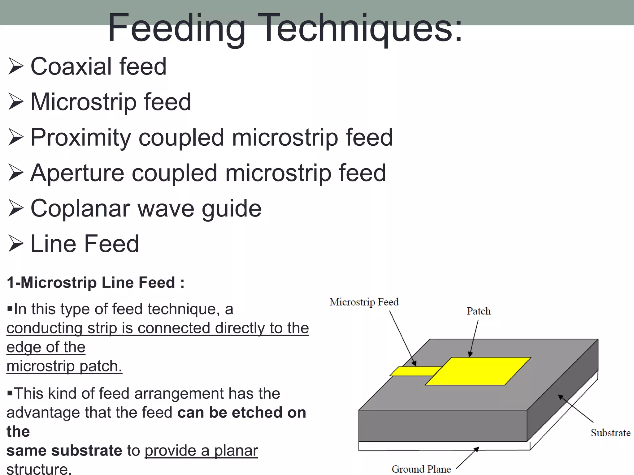


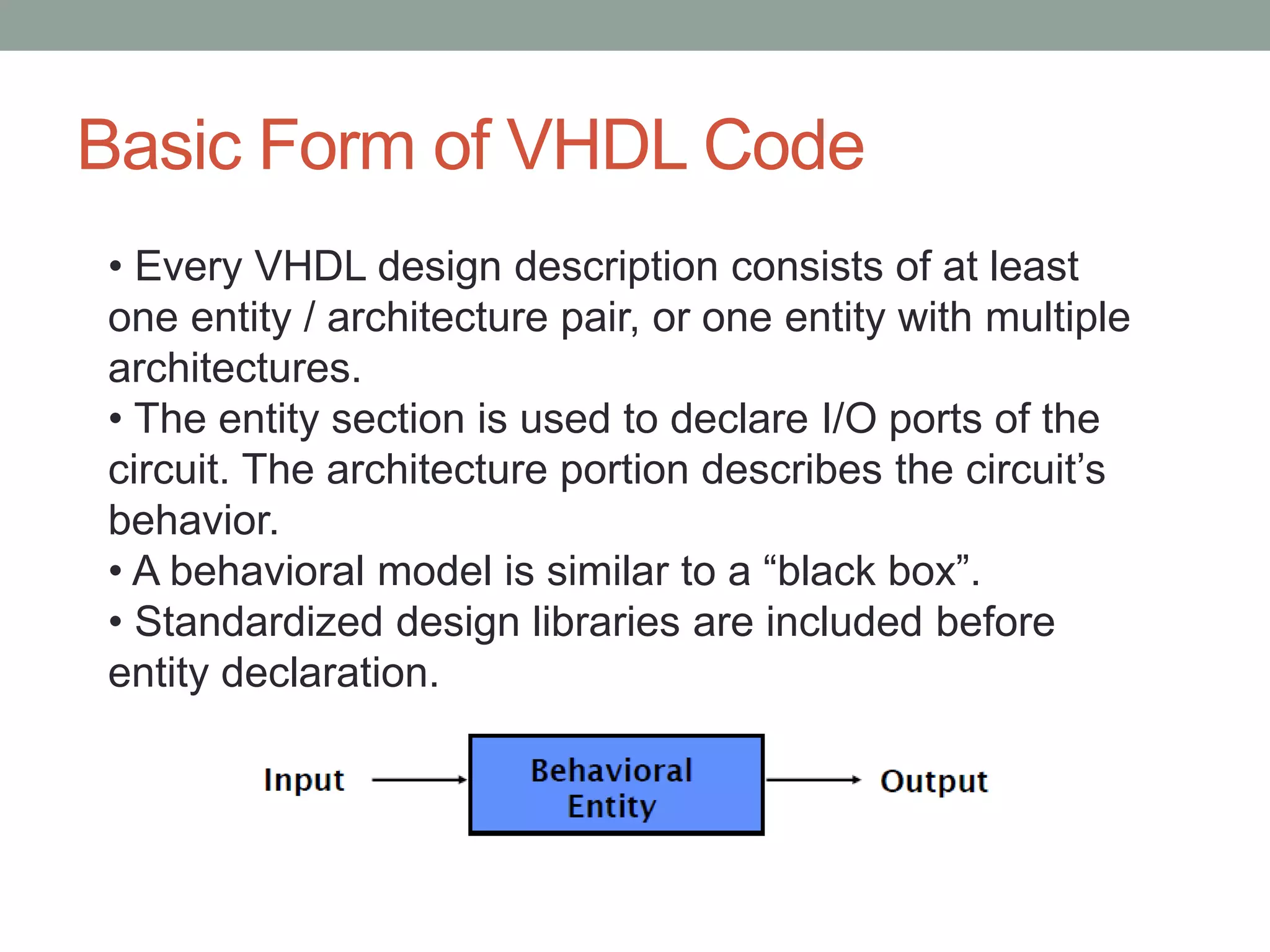


The document summarizes the work done on antenna design and VHDL coding during a summer training. It describes designing a 1.575 GHz microstrip patch antenna using HFSS software. Key steps included selecting a patch shape and substrate, specifying design requirements, and simulating results. It also provides an introduction to VHDL, describing its basic structure, libraries, modeling styles (behavioral, data flow, structural), and hierarchy. Simulation results showed the antenna achieved less than 2 VSWR and 3.8% bandwidth at the target frequency.