Downloaded 363 times
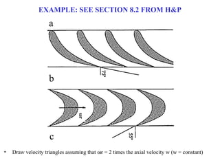
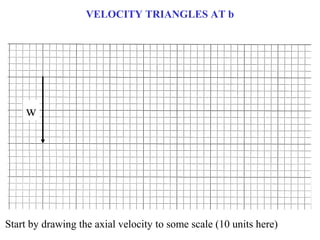
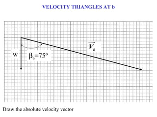
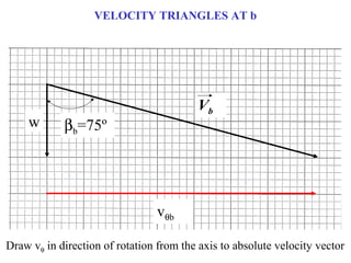
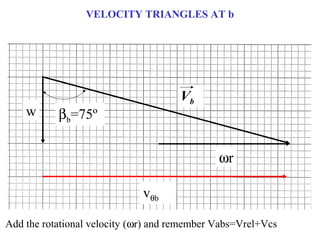
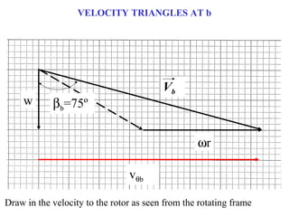
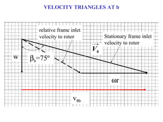
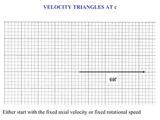
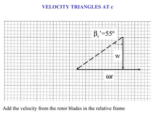
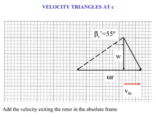
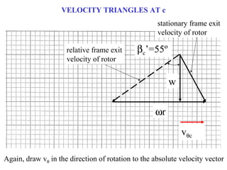
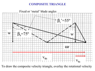

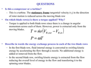
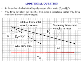
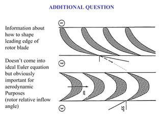

1) The document provides an example of using velocity triangles to analyze a turbine. It shows the velocity triangles drawn at two blade rows labeled b and c. 2) At each blade row, the axial, tangential, and absolute velocities are drawn to scale on the velocity triangle diagrams. This is done in both the stationary and relative frames. 3) The example calculates the torque applied to each blade row based on the change in angular momentum across it. It also describes the energy exchange process at each blade row, with kinetic energy being extracted from the flow by the moving blades.