Advanced Mine Surveying
Lecture_II
Introduction to Advanced Mine Surveying
Prepared By: Mr. Hailu G.
Aksum University, Aksum
Mobile: 0914838991
Mail: hailug.yohannes@gmail.com
Aksum University
2.
TRIANGULATION
Triangulation isone of the methods of fixing accurate horizontal controls
points.
It is based on the trigonometric proposition that if one side and two angles
of a triangle are known, the remaining sides can be computed.
A triangulation system consists of a series of joined or overlapping
triangles in which an occasional side called as base line, is measured and
remaining sides are calculated from the angles measured at the vertices of
the triangles.
3.
CLASSIFICATION OF TRIANGULATIONSYSTEM
• The classification of triangulation figures is the accuracy with which the
length and azimuth of a line of the triangulation are determined.
• Classification Triangulation systems of different accuracies depend on the
extent and the purpose of the survey.
• The accepted grades of triangulation are:
First order or Primary Triangulation
Second order or Secondary Triangulation
Third order or Tertiary Triangulation
4.
First order orPrimary Triangulation
• The first order triangulation is of the highest order and is employed either to
determine the earth’s figure or to furnish the most precise control points
to which secondary triangulation may be connected.
specifications of the primary triangulation:
Average triangle closure: Less than 1 second
Maximum triangle closure: Not more than 3 seconds
Length of base line: 5 to 15 kilometers
Length of the sides of triangles: 30 to 150 kilometers
5.
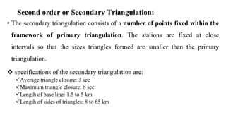
Second order orSecondary Triangulation:
• The secondary triangulation consists of a number of points fixed within the
framework of primary triangulation. The stations are fixed at close
intervals so that the sizes triangles formed are smaller than the primary
triangulation.
specifications of the secondary triangulation are:
Average triangle closure: 3 sec
Maximum triangle closure: 8 sec
Length of base line: 1.5 to 5 km
Length of sides of triangles: 8 to 65 km
6.
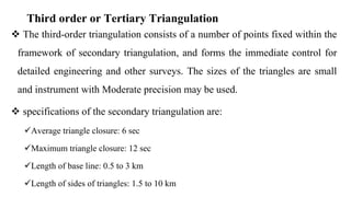
Third order orTertiary Triangulation
The third-order triangulation consists of a number of points fixed within the
framework of secondary triangulation, and forms the immediate control for
detailed engineering and other surveys. The sizes of the triangles are small
and instrument with Moderate precision may be used.
specifications of the secondary triangulation are:
Average triangle closure: 6 sec
Maximum triangle closure: 12 sec
Length of base line: 0.5 to 3 km
Length of sides of triangles: 1.5 to 10 km
7.
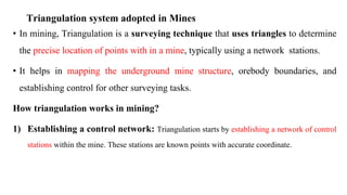
Triangulation system adoptedin Mines
• In mining, Triangulation is a surveying technique that uses triangles to determine
the precise location of points with in a mine, typically using a network stations.
• It helps in mapping the underground mine structure, orebody boundaries, and
establishing control for other surveying tasks.
How triangulation works in mining?
1) Establishing a control network: Triangulation starts by establishing a network of control
stations within the mine. These stations are known points with accurate coordinate.
8.
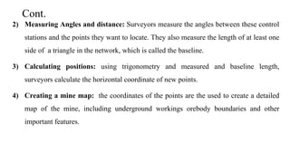
Cont.
2) Measuring Anglesand distance: Surveyors measure the angles between these control
stations and the points they want to locate. They also measure the length of at least one
side of a triangle in the network, which is called the baseline.
3) Calculating positions: using trigonometry and measured and baseline length,
surveyors calculate the horizontal coordinate of new points.
4) Creating a mine map: the coordinates of the points are the used to create a detailed
map of the mine, including underground workings orebody boundaries and other
important features.
9.
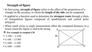
Strength of figure
•In Surveying, strength of figure refers to the effect of the proportions of a
triangle on the accuracy in which the length of the side can be computed.
• It applied to a function used to determine the strongest route through a chain
of triangulation figures composed of quadrilaterals and central point
polygons.
• When small errors in angle measurement affect the computed distances to a
lesser extent the figure is said to be strong.
For example to compute CD
Δ ABC ~ Δ ADC
Δ ABC ~ Δ CBD
Δ ABD ~ Δ ADC
Δ ABD ~ Δ BDC
10.
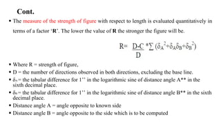
Cont.
The measureof the strength of figure with respect to length is evaluated quantitatively in
terms of a factor ‘R’. The lower the value of R the stronger the figure will be.
Where R = strength of figure,
D = the number of directions observed in both directions, excluding the base line.
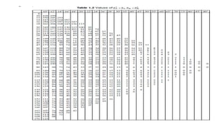
δA = the tabular difference for 1’’ in the logarithmic sine of distance angle A** in the
sixth decimal place.
δB = the tabular difference for 1’’ in the logarithmic sine of distance angle B** in the sixth
decimal place.
Distance angle A = angle opposite to known side
Distance angle B = angle opposite to the side which is to be computed
11.
Cont.
D= thenumber of directions observed excluding the known side.
D=2 × (n' – 1)
C = the number of geometric conditions.
C= (n’- s’+1) + (n-2s+3)
n = total number of lines
s = total number of stations
n’ = total number of lines observed in both directions (lines observed in one direction only
are usually shown by broken lines)
s’ = total number of stations occupied
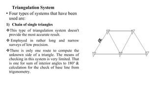
Triangulation System
• Fourtypes of systems that have been
used are:
1) Chain of single triangles
This type of triangulation system doesn't
provide the most accurate result.
Employed in rather long and narrow
surveys of low precision.
There is only one route to compute the
unknown side of a triangle. The means of
checking in this system is very limited. That
is one for sum of interior angles to 180° &
calculation for the check of base line from
trigonometry.
14.
Cont.
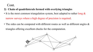
2) Chain ofquadrilaterals formed with overlying triangles
• It is the most common triangulation system, best adapted to rather long &
narrow surveys where a high degree of precision is required.
• The sides can be computed with different routes as well as different angles &
triangles offering excellent checks for the computation.
15.
Cont.
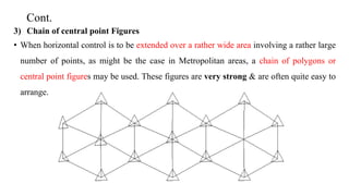
3) Chain ofcentral point Figures
• When horizontal control is to be extended over a rather wide area involving a rather large
number of points, as might be the case in Metropolitan areas, a chain of polygons or
central point figures may be used. These figures are very strong & are often quite easy to
arrange.
16.
Cont.
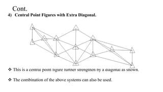
4) Central PointFigures with Extra Diagonal.
This is a central point figure further strengthen by a diagonal as shown.
The combination of the above systems can also be used.
17.
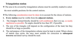
Triangulation station
Thearea to be covered by triangulation scheme must be carefully studied to select
the most suitable positions for the control stations.
The following consideration must be taken in to account for the choice of stations.
1. Every station must be visible from the adjacent stations.
2. The triangles formed thereby should be well conditioned, that is to say, as nearly
equilateral as possible. No angles should be less than 30°, if possible.
3. The size of the triangles will depend on the configuration of the land, but they
should be as large as possible.
4. The end purpose of the triangulation scheme must be kept in mind. Where choice
of station sites exists, the once most suitable for correction to subsequent
traverse and detail survey should be used.
18.
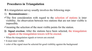
Procedures in Triangulation
Atriangulation survey usually involves the following steps
1) Reconnaissance: -
The first consideration with regard to the selection of stations is inter
visibility. An observation between two stations that are not inter visible is
impossible.
meaning the selection of the most visible points for the station.
2) Signal erection: After the stations have been selected, the triangulation
signals or the triangulation towers will be erected.
• When the triangulation signals or towers are erected:
• It must inter visible
• color of the signal must be selected for good visibility against the background
19.
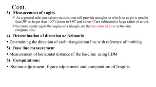
Cont.
3) Measurement ofangles
As a general rule, one selects stations that will provide triangles in which no angle is smaller
than 30º or larger than 150º (closer to 180º and closer 0°are subjected to large ratios of error).
the more nearly equal the angles of a triangle are the less ratio of error in the sine
computations.
4) Determination of direction or Azimuth:
Determining the direction of each triangulation line with reference of northing
5) Base line measurement
Measurement of horizontal distance of the baseline using EDM
5) Computations:
Station adjustment, figure adjustment and computation of lengths.
20.
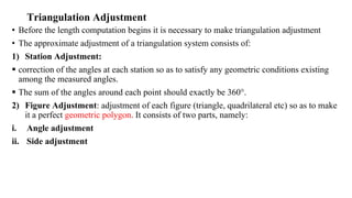
Triangulation Adjustment
• Beforethe length computation begins it is necessary to make triangulation adjustment
• The approximate adjustment of a triangulation system consists of:
1) Station Adjustment:
correction of the angles at each station so as to satisfy any geometric conditions existing
among the measured angles.
The sum of the angles around each point should exactly be 360°.
2) Figure Adjustment: adjustment of each figure (triangle, quadrilateral etc) so as to make
it a perfect geometric polygon. It consists of two parts, namely:
i. Angle adjustment
ii. Side adjustment
21.
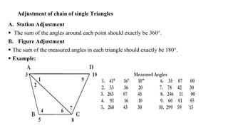
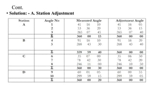
Adjustment of chainof single Triangles
A. Station Adjustment
The sum of the angles around each point should exactly be 360°.
B. Figure Adjustment
The sum of the measured angles in each triangle should exactly be 180°.
Example:
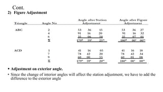
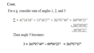
Cont.
2) Figure Adjustment
Adjustment on exterior angle.
• Since the change of interior angles will affect the station adjustment, we have to add the
difference to the exterior angle
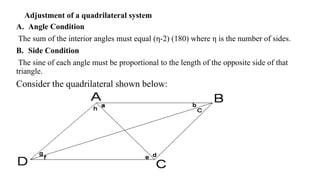
Adjustment of aquadrilateral system
A. Angle Condition
The sum of the interior angles must equal (η-2) (180) where η is the number of sides.
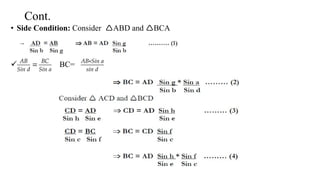
B. Side Condition
The sine of each angle must be proportional to the length of the opposite side of that
triangle.
Consider the quadrilateral shown below:
26.
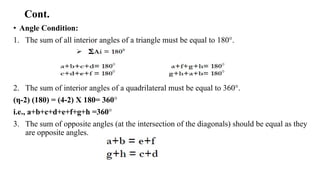
Cont.
• Angle Condition:
1.The sum of all interior angles of a triangle must be equal to 180°.
2. The sum of interior angles of a quadrilateral must be equal to 360°.
(η-2) (180) = (4-2) X 180= 360°
i.e., a+b+c+d+e+f+g+h =360°
3. The sum of opposite angles (at the intersection of the diagonals) should be equal as they
are opposite angles.
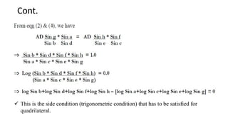
Cont.
This isthe side condition (trigonometric condition) that has to be satisfied for
quadrilateral.
29.
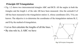
Principle Of Triangulation
•Fig. 1.2 shows two interconnected triangles ABC and BCD. All the angles in both the
triangles and the length L of the side AB have been measured. Also the azimuth θ of
AB has been measured at the triangulation station A, whose coordinates (XA, YA), are
known. The objective is to determine the coordinates of the triangulation stations B, C,
and D by the method of triangulation.
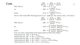
• Let us first calculate the lengths of all the lines.
• By sine rule in, Δ ABC we have
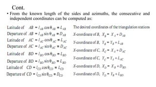
Cont.
• From theknown length of the sides and azimuths, the consecutive and
independent coordinates can be computed as:
32.
Different types ofapplication of triangulation survey
• Triangulation surveys are used to Establish accurate control points for
various purposes, including
1) Mapping and geodesy:
For large scale mapping and geodetic surveys, ensuring the precision of maps
and coordinate system
2) Engineering projects:
To precisely locate and align major engineering structures like bridges, tunnels and
other infrastructure, ensuring accuracy in construction and design.
3) Photogrammetry:
• Triangulation provides ground control points for photogrammetric surveys which use
aerial photographs to create maps.