Download as PDF, PPTX
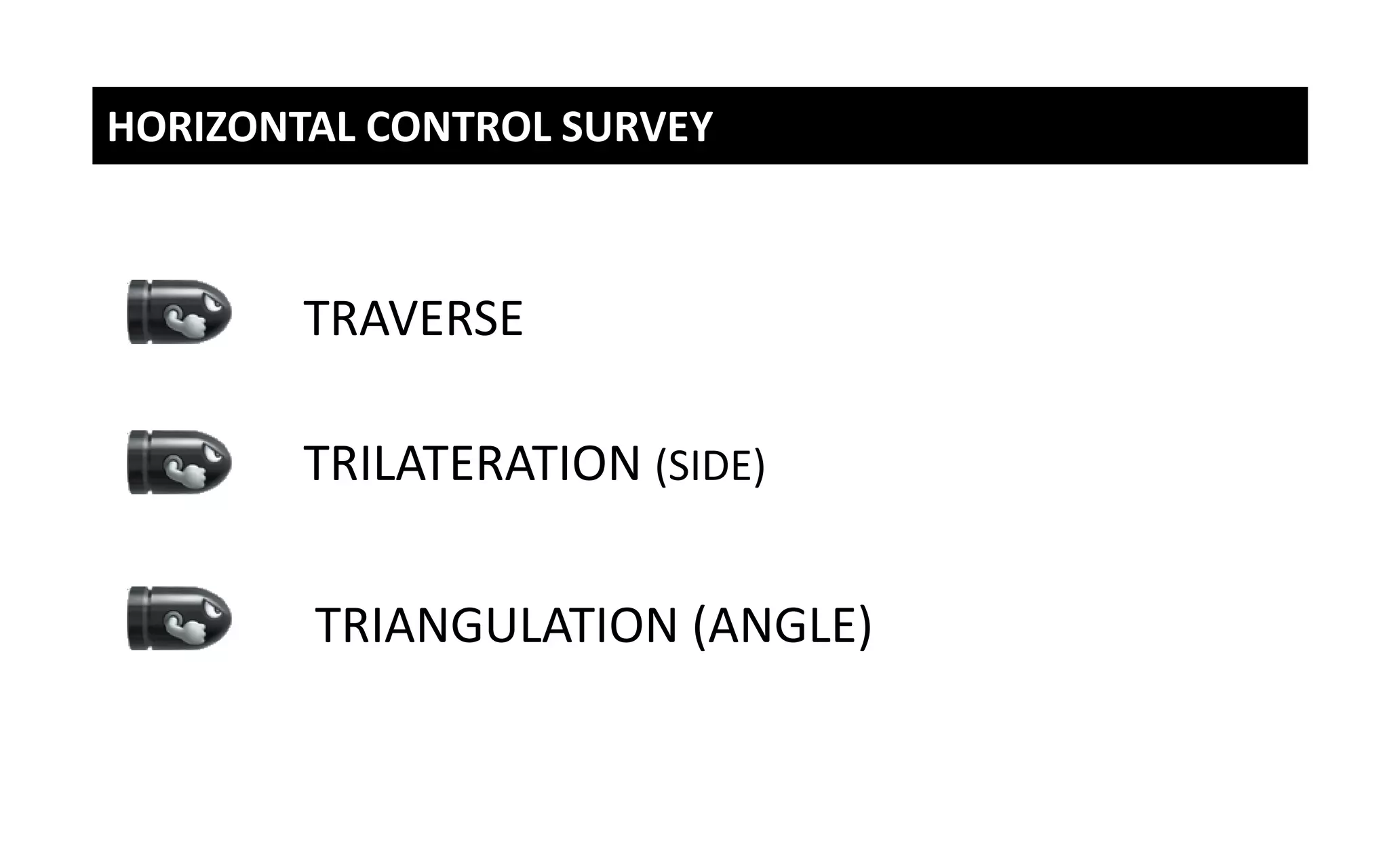

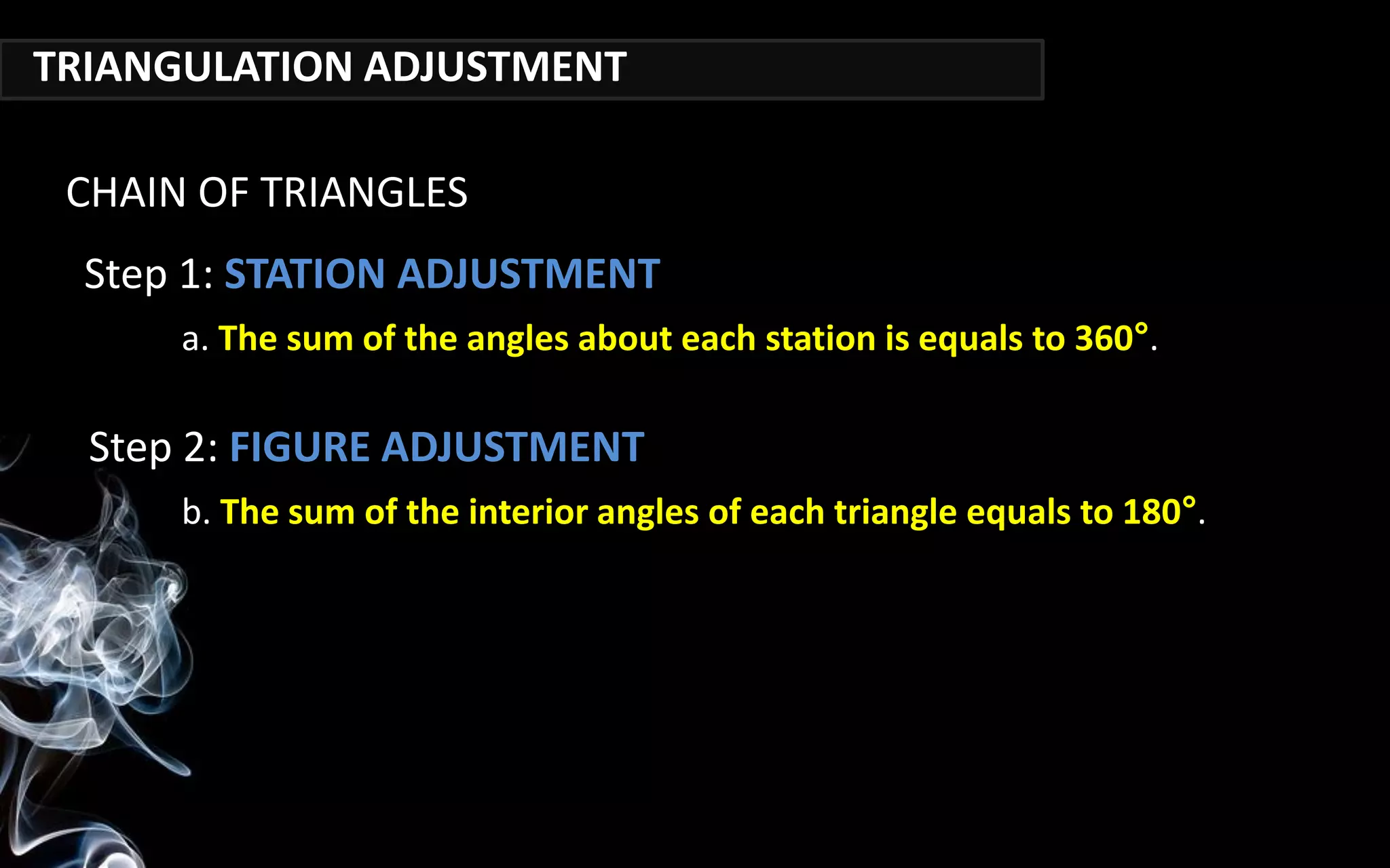
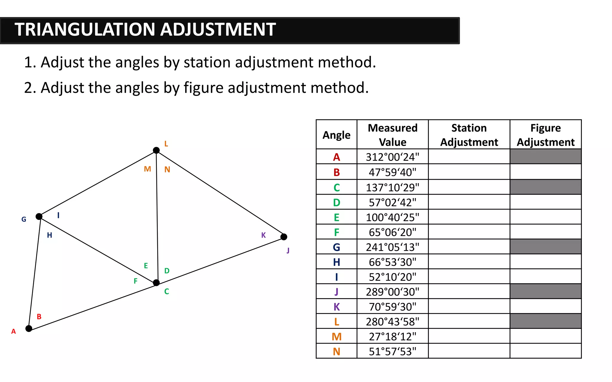
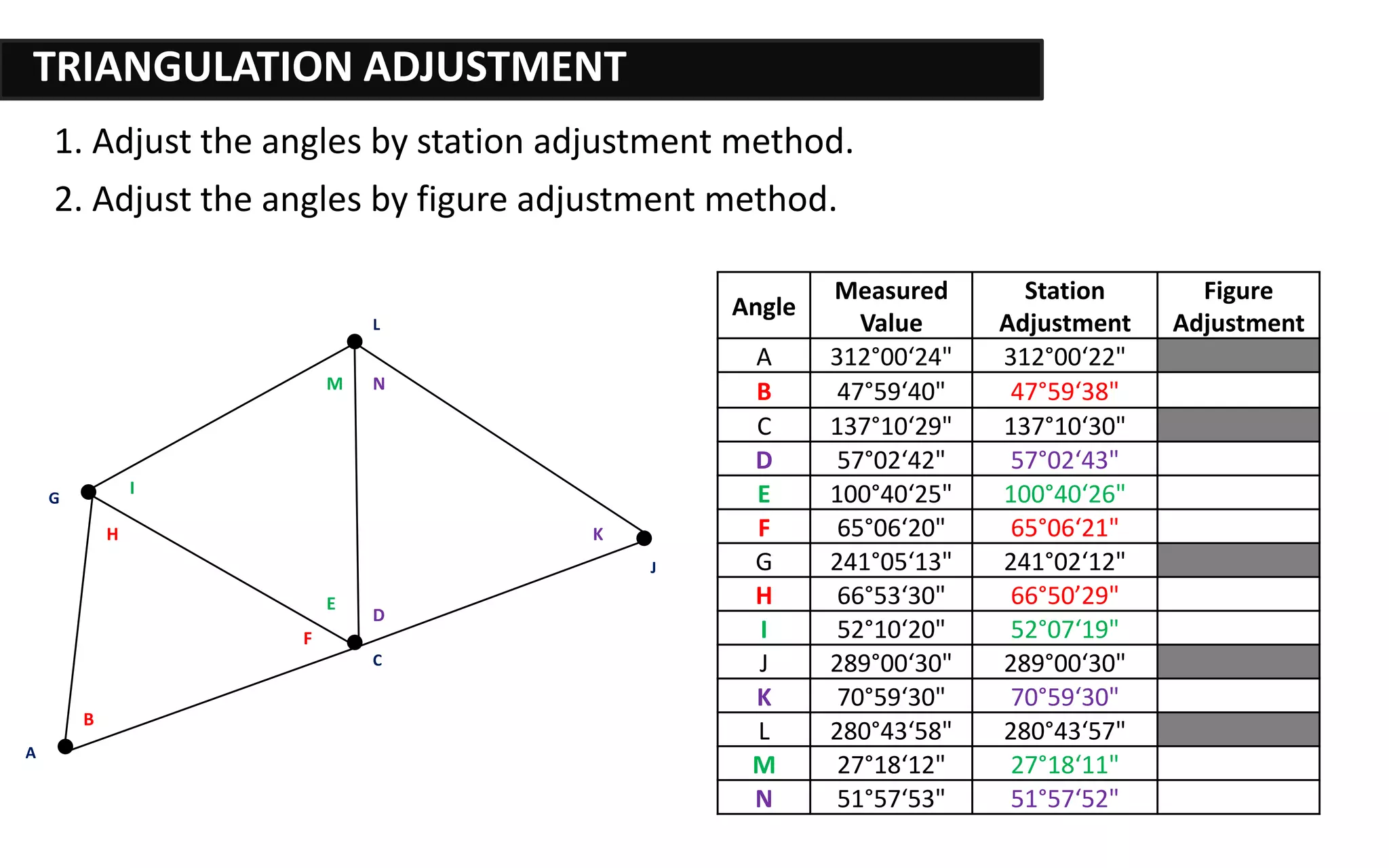
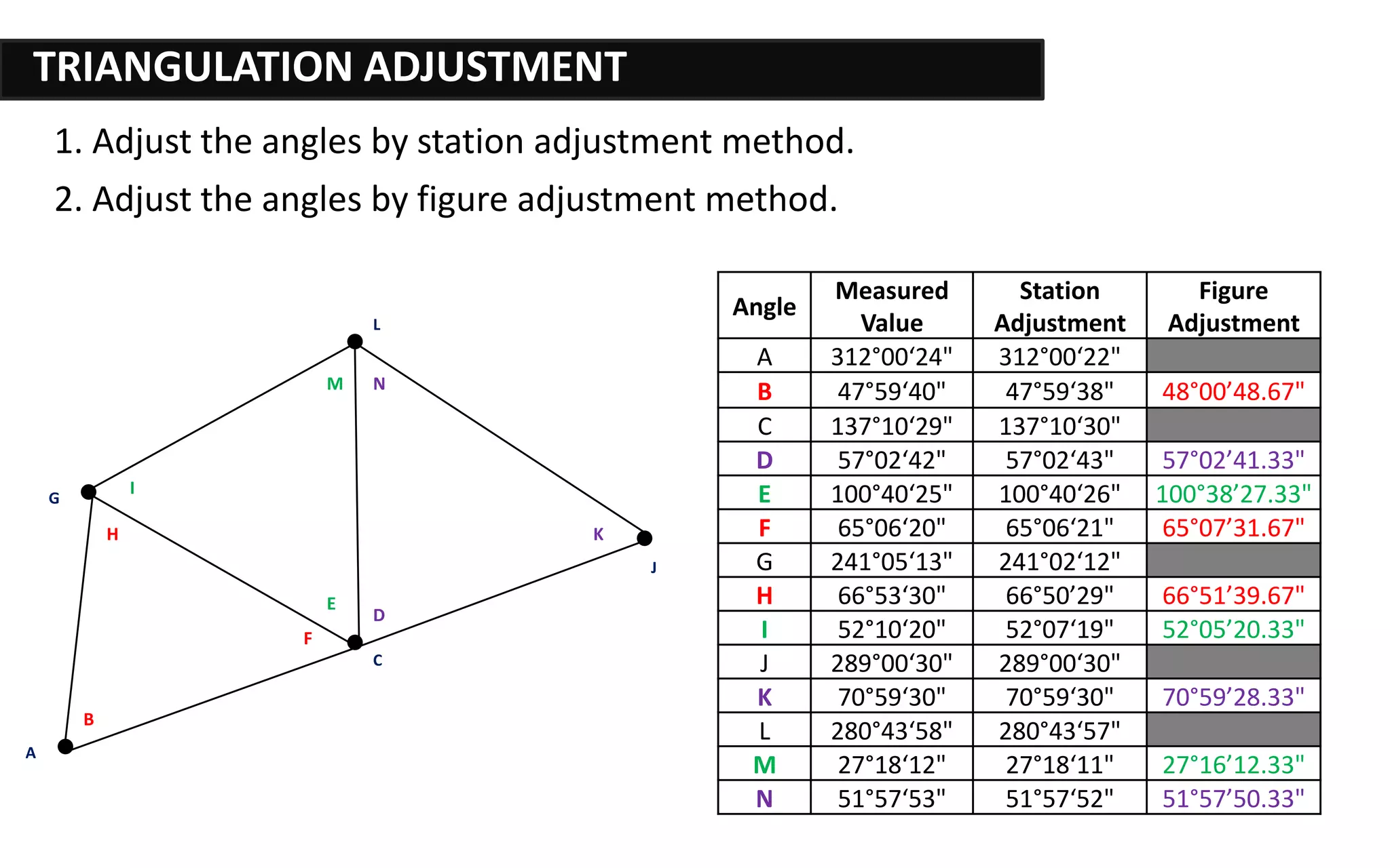
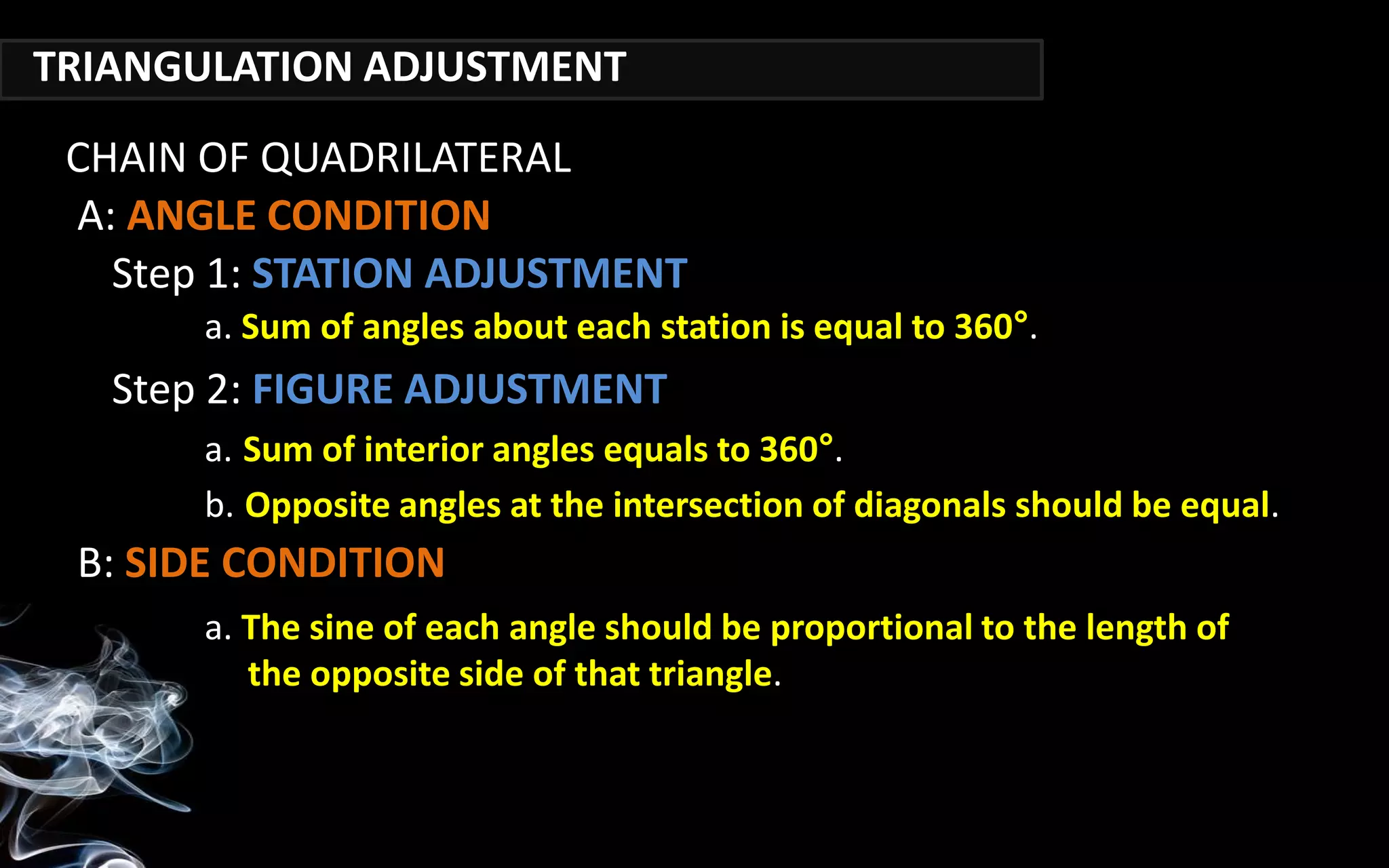
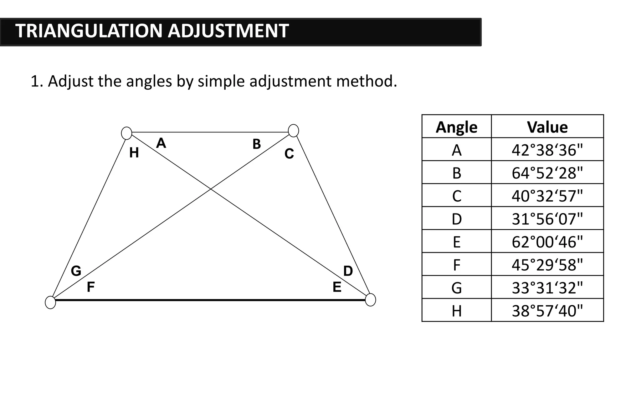
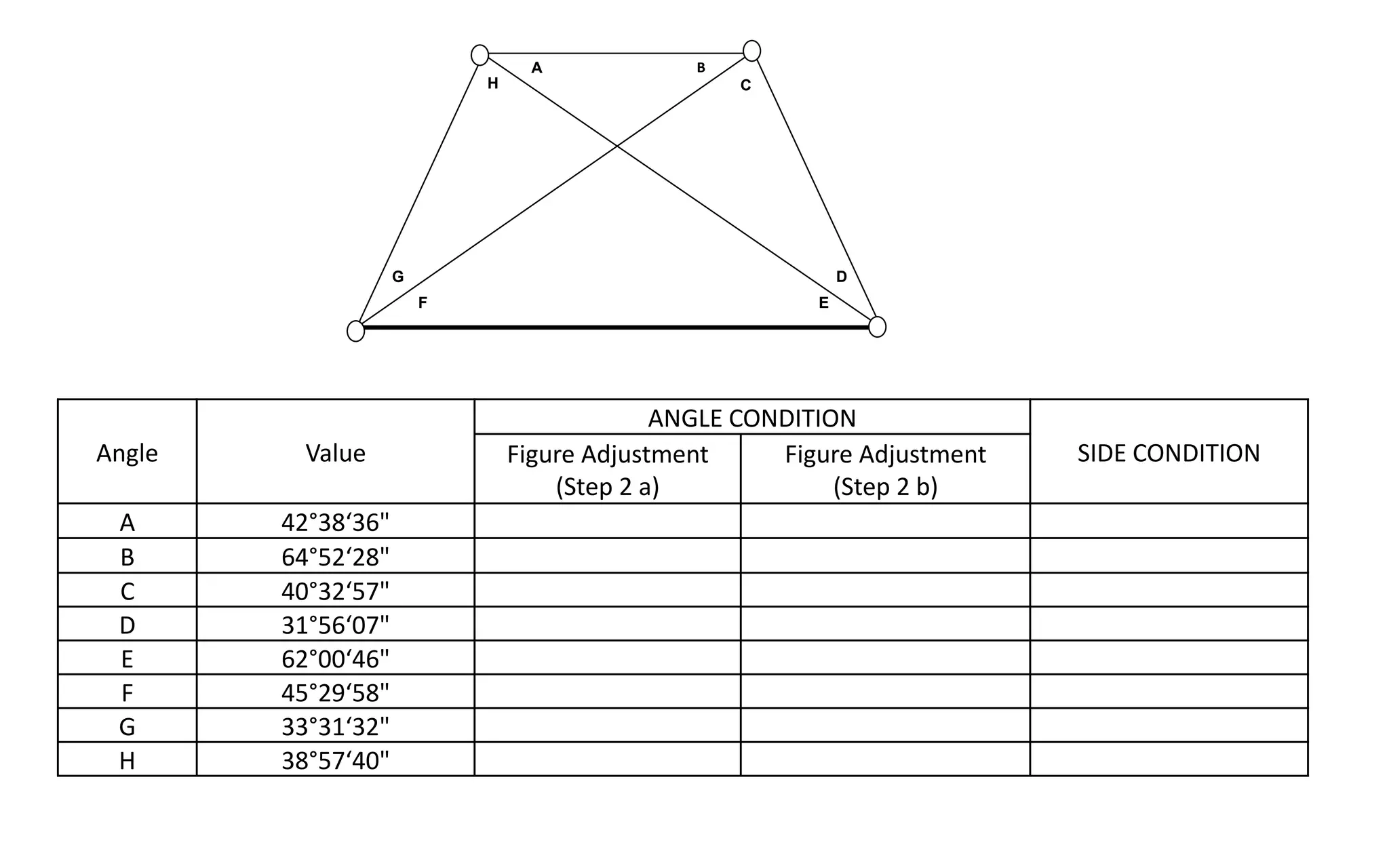
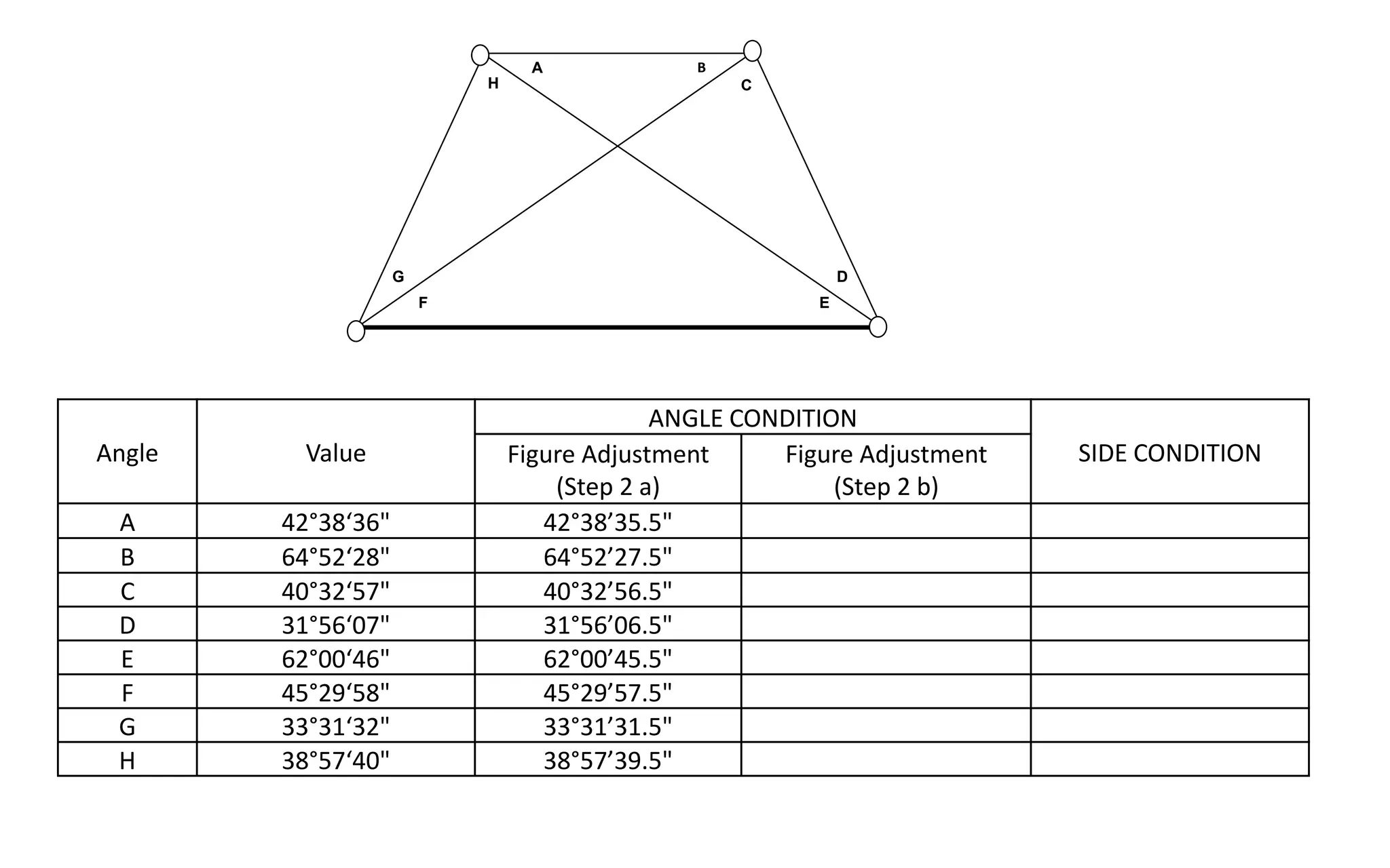
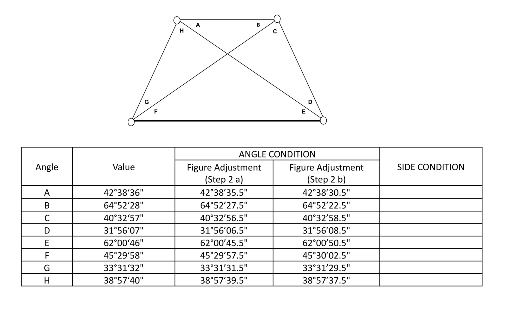
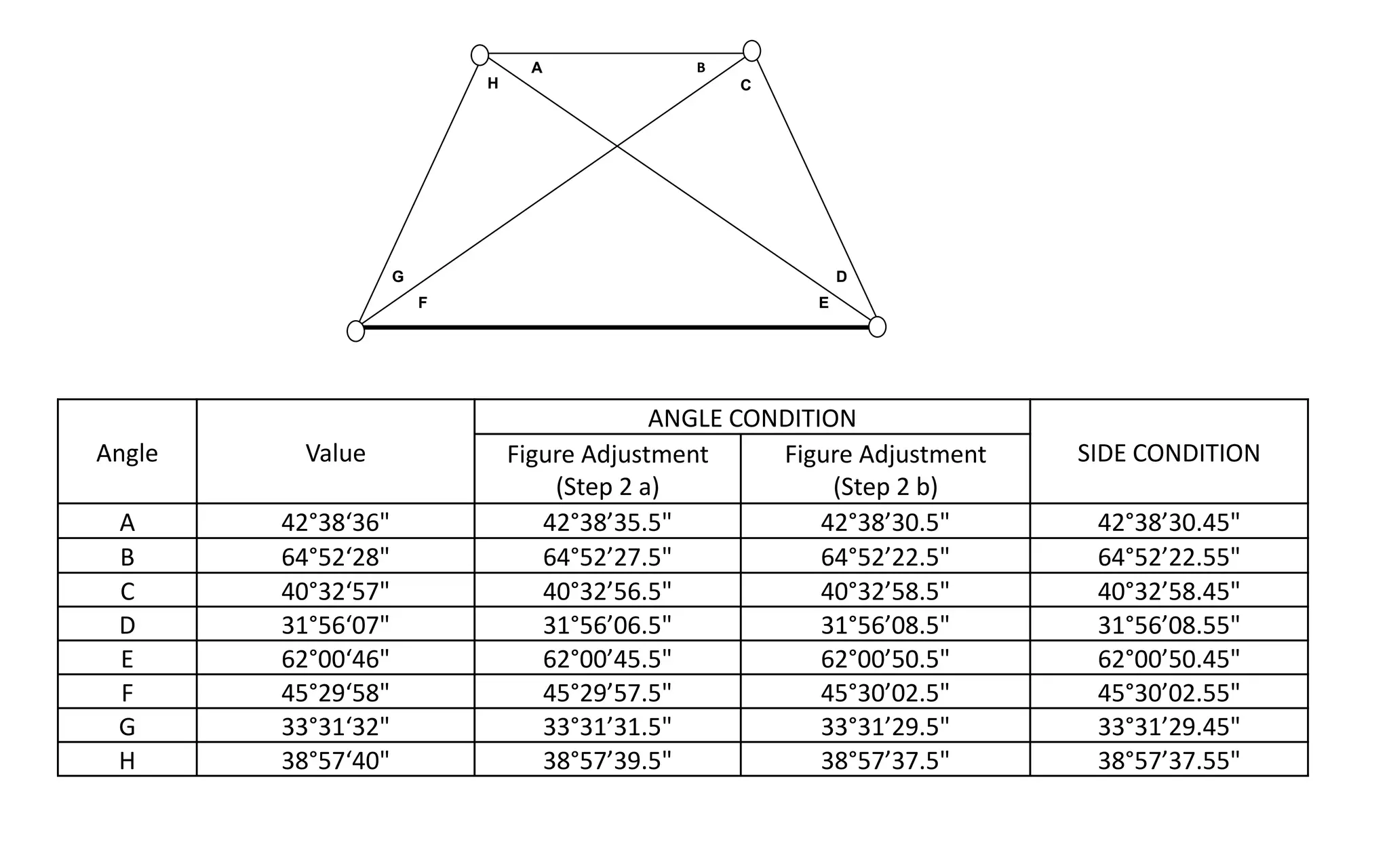
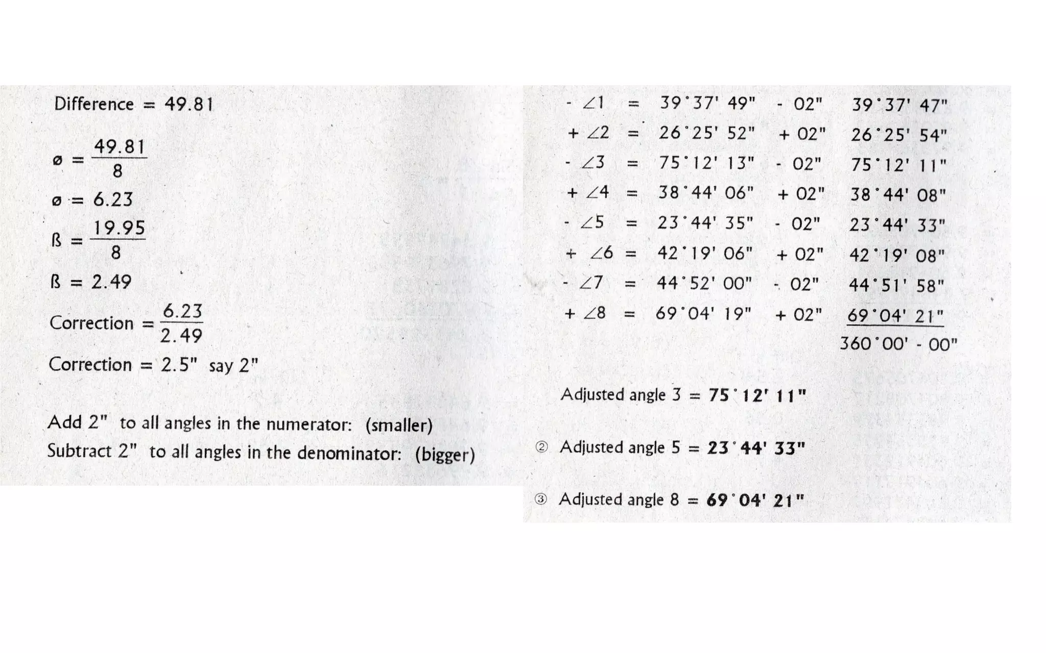

The document outlines methods for triangulation adjustment techniques in surveying, focusing on angle adjustments by various methods including station and figure adjustments. It emphasizes that the sum of angles at each station must equal 360° and provides detailed adjustments for measured angles across multiple triangles. Additionally, it discusses adjustments for quadrilaterals and includes a structured approach to both angle and side conditions in figure adjustment methods.