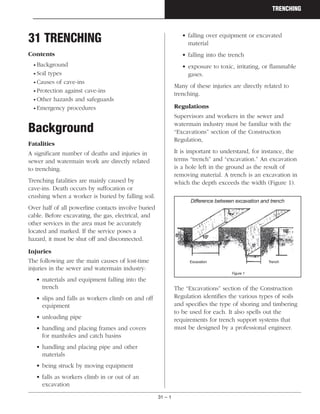
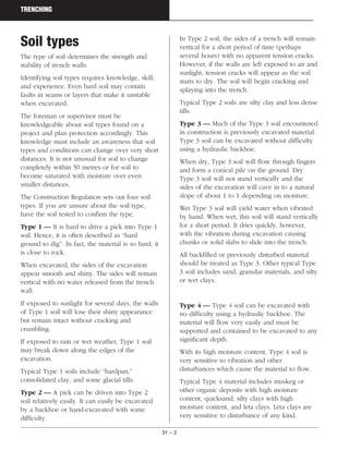
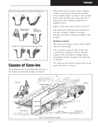
SlideShare a Scribd company logo
31 – 1
TRENCHING
31 TRENCHING
Contents
• Background
• Soil types
• Causes of cave-ins
• Protection against cave-ins
• Other hazards and safeguards
• Emergency procedures
Background
Fatalities
A significant number of deaths and injuries in
sewer and watermain work are directly related
to trenching.
Trenching fatalities are mainly caused by
cave-ins. Death occurs by suffocation or
crushing when a worker is buried by falling soil.
Over half of all powerline contacts involve buried
cable. Before excavating, the gas, electrical, and
other services in the area must be accurately
located and marked. If the service poses a
hazard, it must be shut off and disconnected.
Injuries
The following are the main causes of lost-time
injuries in the sewer and watermain industry:
• materials and equipment falling into the
trench
• slips and falls as workers climb on and off
equipment
• unloading pipe
• handling and placing frames and covers
for manholes and catch basins
• handling and placing pipe and other
materials
• being struck by moving equipment
• falls as workers climb in or out of an
excavation
• falling over equipment or excavated
material
• falling into the trench
• exposure to toxic, irritating, or flammable
gases.
Many of these injuries are directly related to
trenching.
Regulations
Supervisors and workers in the sewer and
watermain industry must be familiar with the
“Excavations” section of the Construction
Regulation,
It is important to understand, for instance, the
terms “trench” and “excavation.” An excavation
is a hole left in the ground as the result of
removing material. A trench is an excavation in
which the depth exceeds the width (Figure 1).
The “Excavations” section of the Construction
Regulation identifies the various types of soils
and specifies the type of shoring and timbering
to be used for each. It also spells out the
requirements for trench support systems that
must be designed by a professional engineer.
Difference between excavation and trench
Figure 1
Excavation
10'
5'
10'
5'
Trench
31 – 2
TRENCHING
Soil types
The type of soil determines the strength and
stability of trench walls.
Identifying soil types requires knowledge, skill,
and experience. Even hard soil may contain
faults in seams or layers that make it unstable
when excavated.
The foreman or supervisor must be
knowledgeable about soil types found on a
project and plan protection accordingly. This
knowledge must include an awareness that soil
types and conditions can change over very short
distances. It is not unusual for soil to change
completely within 50 metres or for soil to
become saturated with moisture over even
smaller distances.
The Construction Regulation sets out four soil
types. If you are unsure about the soil type,
have the soil tested to confirm the type.
Type 1 — It is hard to drive a pick into Type 1
soil. Hence, it is often described as “hard
ground to dig”. In fact, the material is so hard, it
is close to rock.
When excavated, the sides of the excavation
appear smooth and shiny. The sides will remain
vertical with no water released from the trench
wall.
If exposed to sunlight for several days, the walls
of Type 1 soil will lose their shiny appearance
but remain intact without cracking and
crumbling.
If exposed to rain or wet weather, Type 1 soil
may break down along the edges of the
excavation.
Typical Type 1 soils include “hardpan,”
consolidated clay, and some glacial tills.
Type 2 — A pick can be driven into Type 2
soil relatively easily. It can easily be excavated
by a backhoe or hand-excavated with some
difficulty.
In Type 2 soil, the sides of a trench will remain
vertical for a short period of time (perhaps
several hours) with no apparent tension cracks.
However, if the walls are left exposed to air and
sunlight, tension cracks will appear as the soil
starts to dry. The soil will begin cracking and
splaying into the trench.
Typical Type 2 soils are silty clay and less dense
tills.
Type 3 — Much of the Type 3 soil encountered
in construction is previously excavated material.
Type 3 soil can be excavated without difficulty
using a hydraulic backhoe.
When dry, Type 3 soil will flow through fingers
and form a conical pile on the ground. Dry
Type 3 soil will not stand vertically and the
sides of the excavation will cave in to a natural
slope of about 1 to 1 depending on moisture.
Wet Type 3 soil will yield water when vibrated
by hand. When wet, this soil will stand vertically
for a short period. It dries quickly, however,
with the vibration during excavation causing
chunks or solid slabs to slide into the trench.
All backfilled or previously disturbed material
should be treated as Type 3. Other typical Type
3 soil includes sand, granular materials, and silty
or wet clays.
Type 4 — Type 4 soil can be excavated with
no difficulty using a hydraulic backhoe. The
material will flow very easily and must be
supported and contained to be excavated to any
significant depth.
With its high moisture content, Type 4 soil is
very sensitive to vibration and other
disturbances which cause the material to flow.
Typical Type 4 material includes muskeg or
other organic deposits with high moisture
content, quicksand, silty clays with high
moisture content, and leta clays. Leta clays are
very sensitive to disturbance of any kind.
31 – 3
TRENCHING
Causes of Cave-Ins
Soil properties often vary widely from the top to
the bottom and along the length of a trench.
Many factors such as cracks, water, vibration,
weather, and previous excavation can affect
trench stability (Figure 2). Time is also a critical
factor. Some trenches will remain open for a
long period, then suddenly collapse for no
apparent reason.
Figure 3 shows the typical causes of cave-ins.
The main factors affecting trench stability are
soil type, moisture, vibration, surcharge,
previous excavation, existing foundations, and
weather.
Moisture content
The amount of moisture in the soil has a great
effect on soil strength.
Once a trench is dug, the sides of the open
excavation are exposed to the air. Moisture
content of the soil begins to change almost
immediately and the strength of the walls may
be affected.
The longer an excavation is open to the air, the
greater the risk of a cave-in.
Trench open for extended duration may collapse without apparent reason.
Equipment vibration
affects stability.
Backfill is
less stable than
undisturbed soil.
Surcharge such as spoil pile puts more pressure on trench walls.
Figure 3
Large Load
Rain
Insufficient Shoring
Vibration
Cracks
Broken Line High Water TableWater Seepage
Settling
Figure 2 - Many factors affect trench stability.
31 – 4
TRENCHING
Vibration
Vibration from various sources can affect trench
stability.
Often trench walls are subject to vibration from
vehicular traffic or from construction operations
such as earth moving, compaction, pile driving,
and blasting. These can all contribute to the
collapse of trench walls.
Surcharge
A surcharge is an excessive load or weight that
can affect trench stability.
For instance, excavated soil piled next to the
trench can exert pressure on the walls.
Placement of spoil piles is therefore important.
Spoil should be kept as far as is practical from
the edge of the trench. Mobile equipment and
other material stored close to the trench also
add a surcharge that will affect trench stability.
One metre from the edge to the toe of the spoil
pile is the minimum distance requirement
(Figure 4). The distance should be greater for
deeper trenches.
Previous excavation
Old utility trenches either crossing or running
parallel to the new trench can affect the strength
and stability (Figure 5).
Soil around and between these old excavations
can be very unstable. At best it is considered
Type 3 soil — loose, soft, and low in internal
strength. In some unusual circumstances it may
be Type 4 — wet, muddy, and unable to
support itself.
This kind of soil will not stand up unless it is
sloped or shored.
Existing foundations
Around most trenches and excavations there is a
failure zone where surcharges, changes in soil
condition, or other disruptions can cause
collapse.
When the foundation of a building adjacent to
the trench or excavation extends into this failure
zone, the result can be a cave-in (Figure 6). Soil
in this situation is usually considered Type 3.
Weather
Rain, melting snow, thawing earth, and overflow
from adjacent streams, storm drains, and sewers
all produce changes in soil conditions. In fact,
water from any source can reduce soil cohesion
(Figure 7).
Existing foundations are surrounded by
backfill and may add a surcharge load to the pressure on the trench wall.
Figure 6
Move spoil pile farther back for deep trenches
Figure 4
Old utilities are surrounded by backfilled soil which is usually
less stable than undisturbed soil.
Figure 5
1m 1m 1m
31 – 5
TRENCHING
Frozen soil does not mean that you can have
reduced shoring or that a heavier load can be
supported. Frost extends to a limited depth only.
Protection Against
Cave-Ins
There are three basic methods of protecting
workers against trench cave-ins:
• sloping
• trench boxes
• shoring
Most fatal cave-ins occur on small jobs of short
duration such as service connections and
excavations for drains and wells. Too often
people think that these jobs are not hazardous
enough to require safeguards against collapse.
Unless the walls are solid rock, never enter a
trench deeper than 1.2 metres (4 feet) if it is not
properly sloped, shored, or protected by a
trench box.
Sloping
One way to ensure that a trench will not
collapse is to slope the walls.
Where space and other requirements permit
sloping, the angle of slope depends on soil
conditions (Figures 8, 9 and 10).
For Type 1 and 2 soils, cut trench walls back at
an angle of 1 to 1 (45 degrees). That's one
metre back for each metre up. Walls should be
sloped to within 1.2 metres (4 feet) of the
trench bottom (Figure 8).
For Type 3 soil, cut walls back at a gradient of 1
to 1 from the trench bottom (Figure 9).
For Type 4 soil, slope the walls at 1 to 3. That’s
3 metres back for every 1 metre up from the
trench bottom (Figure 10).
Although sloping can reduce the risk of a cave-in,
the angle must be sufficient to prevent spoil not
only from sliding back but also from exerting too
much pressure on the trench wall (Figure 11).
Sloping is commonly used with shoring or
trench boxes to cut back any soil above the
protected zone. It is also good practice to cut a
bench at the top of the shoring or trench
(Figure 12).
Moisture affects stability, especially where heavy rainfall has occurred
Figure 7
GOOD SOIL Type 1 & 2 Soil
Minimum
Bank SlopeMaximum
1.2 m (4 ft.)
Figure 8
Figure 10
Figure 9
FAIRLY GOOD SOIL Type 3 Soil
Minimum
Bank Slope
BAD SOIL Type 4 Soil
Minimum
Bank Slope
Spoil piles can exert too much pressure on sloped trench wall.
Figure 11
31 – 6
TRENCHING
If sloping is to be used above a trench box, the
top portion of the cut should first be sloped 1 to
1 (or 1 to 3 for Type 4 soil — see previous
page). Then the box should be lowered into the
trench (Figure 13).
Trench boxes
Trench boxes are not usually intended to shore
up or otherwise support trench walls. They are
meant to protect workers in case of a cave-in.
Design drawings and specifications for trench
boxes must be signed and sealed by the
professional engineer who designed the system
and must be kept on site by the constructor.
Boxes are normally placed in an excavated but
unshored trench and used to protect personnel.
A properly designed trench box is capable of
withstanding the maximum lateral load expected
at a given depth in a particular soil condition.
Trenches near utilities, streets, and buildings
may require a shoring system.
As long as workers are in the trench they
should remain inside the box. Workers must not
be inside the trench or the box when the box is
being moved. A ladder must be set up in the
trench box at all times.
Excavation should be done so that the space
between the trench box and the excavation is
minimized (Figure 14).
The two reasons for this are
1)allowing closer access to the top of the
box
2)limiting soil movement in case of a
cave-in.
Check the drawings and specifications for the
trench box to see if the space between the box
and the trench wall needs to be backfilled and
the soil compacted.
Shoring
Shoring is a system which “shores” up or
supports trench walls to prevent movement of
soil, underground utilities, roadways, and
foundations.
Shoring should not be confused with trench
boxes. A trench box provides worker safety but
gives little or no support to trench walls or
existing structures such as foundations and
manholes.
The two types of shoring most commonly used
are timber and hydraulic. Both consist of posts,
wales, struts, and sheathing.
Figures 15 and 16 identify components,
dimensions, and other requirements for timber
shoring in some typical trenches.
Keep space between trench box and excavation as small as possible.
Backfill
if necessary
to prevent a
cave-in.
Figure 14
Cut back unshored top position with a 1 to 1 slope
(or a 1 to 3 slope for Type 4 soil)
Figure 13
Figure 12
It is good practice to cut a
bench at top of shoring
31 – 7
TRENCHING
“Hydraulic shoring” refers to prefabricated strut
and/or wale systems in aluminum or steel. Strictly
speaking, these may not operate hydraulically.
Some are air-operated or manually jacked. Design
drawings and specifications for prefabricated
shoring systems must be kept on site.
One major advantage of hydraulic shoring over
some applications of timber shoring is safety
during installation. Workers do not have to enter
the trench to install the system. Installation can
be done from the top of the trench.
Most hydraulic systems are
• light enough to be installed by one worker
• gauge-regulated to ensure even distribution
of pressure along the trench line
• able to “pre-load” trench walls, thereby
using the soil's natural cohesion to prevent
movement.
• easily adapted to suit various trench depths
and widths.
Wherever possible, shoring should be installed
as excavation proceeds. If there is a delay
between digging and shoring, no one must be
allowed to enter the unprotected trench.
All shoring should be installed from the top
down and removed from the bottom up.
Access/egress
Whether protected by sloping, boxes, or shoring,
trenches must be provided with ladders so that
workers can enter and exit safely (Figure 17).
Ladders must
• be placed within the area protected by the
shoring or trench box
• be securely tied off at the top
• extend above the shoring or box by at
least 1 metre (3 feet)
Figure 15
Figure 16
Ladders should
be placed within
shored area and
tied off to prevent
slipping.
Figure 17
31 –8
TRENCHING
• be inspected regularly for damage.
Ladders should be placed as close as possible to
the area where personnel are working and
never more than 7.5 metres (25 feet) away.
Anyone climbing up or down must always face
the ladder and maintain 3-point contact. This
means that two hands and one foot or two feet
and one hand must be on the ladder at all
times.
Maintaining 3-point contact also means hands
must be free for climbing. Tools and materials
should not be carried up or down ladders. Pumps,
small compactors, and other equipment should be
lifted and lowered by methods that prevent injury
from overexertion and falling objects.
Inspection
Inspection is everyone's responsibility. Whatever
the protective system, it should be inspected
regularly.
Check hydraulic shoring for leaks in hoses and
cylinders, bent bases, broken or cracked
nipples, and other damaged or defective parts
(Figure 18).
Check timber shoring before installation. Discard
damaged or defective lumber. After installation,
inspect wales for signs of crushing. Crushing
indicates structural inadequacy and calls for
more struts (Figure 19).
Inspect trench boxes for structural damage,
cracks in welds, and other defects (Figure 20).
During use, check the box regularly and often
to make sure that it is not shifting or settling
much more on one side than the other. If it is,
leave the trench and ask the supervisor to check
for stability.
Check ground surface for tension cracks which
may develop parallel to the trench at a distance
one-half to three-quarters of the trench depth
(Figure 21). If cracks are detected, alert the crew
and check all protective systems carefully.
Check areas adjacent to shoring where water
may have entered the trench. A combination of
water flow and granular soils can lead to
undermining of the trench wall. Such conditions
have caused fatalities.
Finally, make sure that tools, equipment,
material, and spoil are kept at least 1 metre
(3 feet) back from the edge of the trench to
prevent falling objects from striking workers.
Check hydraulic
shoring
for leaks.
Figure 18
Cracked sheathing
Inspect wales
for crushing at struts. Strut off level
Bowed sheathing
and wales
Loose or
missing
cleats
Figure 19
31 –9
TRENCHING
Summary
Sloping, trench boxes, and shoring are meant to
protect workers from the hazards of cave-ins.
The method chosen must meet the specific
requirements of the job at hand. Depending on
application, one method may be better suited to
certain conditions than another.
Whatever the system, inspect it regularly to
make sure that it remains sound and reliable.
Remember: Never enter a trench more than
1.2 metres (4 feet) deep unless it is sloped,
shored, or protected by a trench box.
Other Hazards and
Safeguards
The risk of a cave-in is not the only hazard in
trenching. Injuries and deaths are also related to
six other major areas:
• personal protective equipment
• utilities underground and overhead
• materials handling and housekeeping
• heavy equipment
• traffic control
• confined spaces.
Personal protective equipment
Personal protective equipment is an important
defence against certain types of injury.
Injuries from falling and flying objects, for
instance, can be reduced by wearing hard hats
and eye protection.
Everyone on a construction project must wear
Grade 1 safety boots certified by the Canadian
Standards Association (CSA) as indicated by the
CSA logo on a green triangular patch (Figure 22).
Under the wet, muddy conditions often
encountered in trenching, you may also require
rubber safety boots displaying the same CSA
logo on a green triangular patch.
Deformed Plate
Check welds on
sleeves and struts
for bends
and distortion
Damage
Bent
Strut
Missing
Strut
Figure 20
Sidewall
Check for
tension cracks Strut
Knife edge
Figure 21
31– 10
TRENCHING
It is mandatory for everyone on a construction
project to wear head protection in the form of a
hard hat that complies with the current
Construction Regulation.
Eye protection is strongly recommended to
prevent injuries from construction operations
such as chipping and drilling and site conditions
such as dust.
Personnel exposed for long periods to noisy
equipment should wear hearing protection.
Work in confined spaces such as manholes and
valve chambers may require respiratory
protection against hazardous atmospheres. See
the chapter on Confined Spaces in this manual
for more information.
See the chapters on personal protective
equipment in this manual for more information.
Underground utilities
Locates — Services such as gas, electrical,
telephone, and water lines must be located by
the utility before excavation begins.
Request locates for all the underground utilities
in the area where excavation will be taking
place. The contractor responsible for the work
must contact the owners of any underground
utilities that may be in that location or phone
Ontario One Call (1-800-400-2255). Some
utilities are not part of the Ontario One Call
system. Contact those utilities separately for
locate requests.
The service locate provided by the utility owner
should indicate, using labelled stakes, flags,
and/or paint marks, the centre line of the
underground utility in the vicinity of the
proposed excavation.
The excavator should not work outside of the
area covered by the locate stakeout information
without obtaining an additional stakeout.
Locate stakeout accuracy should be considered
to be 1 metre on either side of the surface
centre line locate unless the locate instructions
specifically indicate other boundary limits.
Where the underground utility cannot be
located within the locate stakeout limits, the
utility owner should be contacted to assist with
the locate.
Figure 22 Existing utility lines may require support.
Figure 23
Figure 24
Have existing
utilities located
before
excavating.
31 –11
TRENCHING
Mechanical excavation equipment should not be
used within the boundary limits of the locate
without first digging a hole or holes using the
procedure below to determine the underground
utility's exact centre line and elevation.
Test holes should, in general, be excavated by
one of the following methods:
(a) machine excavation immediately outside
the boundary limits and then hand digging
laterally until the underground utility is
found; or
(b) (i) hand excavation perpendicular to
the centre line of the locate in cuts of at
least 1 foot in depth;
(ii) mechanical equipment can then be
used carefully to widen the hand-dug
trench to within one foot of the depth
of the hand-dug excavation;
(iii) repeat steps (i) and (ii) until the
utility is located; or
(c) a hydro-excavation system — acceptable
to the owner of the utility — which uses
high-pressure water to break up the cover
material and a vacuum system to remove it
can be used to locate the underground
utility. See the next section for more
information about hydro excavation.
Centre line locates should be provided and test
holes dug where a representative of the utility
identifies
(a) alignment changes
(b) changes in elevation.
Where an underground utility may need support
or where it may shift because of disturbance of
surrounding soil due to excavation, guidelines
for excavation and support should be obtained
from the owner of the utility (Figure 23).
Hydro excavation —
Precautions:
• Before starting work, use barricades and
signs to inform unauthorized personnel to
keep out.
• Employers must ensure that workers are
properly trained on the machine they are
using.
• When exposing underground power
utilities the operators should use bonding
mats.
• Use a fall-protection system when
required.
• Keep clear of the vacuum. It is powerful
and can cause serious injury or even death
if you are caught in the tube.
• Some utility owners set limits for the water
pressure that can be used near their buried
plan. Check with the utility owner before
excavating.
• Excavators can refer to the following for
further information:
- TSSA/ESA Guidelines for Excavations in
the Vicinity of Gas Lines
- Safe Practice Guide Excavating with
Hydrovacs in the Vicinity of
Underground Electrical Plant, available
from IHSA (www.ihsa.ca).
Workers using or in the vicinity of hydro
excavation:
Services should
be exposed first
by hand digging,
then by machine.
Figure 25
31 – 12
TRENCHING
• Keep away from the operation if you are
not directly involved in the work.
• Wear hearing protection if working in
vicinity of the hydrovac truck.
• Be aware of the hazards, such as slips
from the runoff water and ice during the
winter.
• Wear appropriate eye and face protection
such as safety glasses and faceshields.
They will protect you from getting any
airbourne debris (caused by splashing) in
your eyes.
• Keep clear of the vacuum. It is powerful
and can cause serious injury or even death
if you are caught in the tube.
Breaks — Breaks in electrical, gas, and water
services can cause serious injuries, even deaths.
Hitting an underground electrical line can result
in electrocution, while hitting a gas line can
cause an explosion. A broken water line can
release a sudden rush of water, washing out
support systems and causing a cave-in.
Cutting telephone lines can create a serious
problem if emergency calls for police, fire, or
ambulance are required.
In the event of gas line contact, call the gas
company immediately. The company will check
the line and close down the supply if necessary.
If a leak is suspected, people in the immediate
area should be told to evacuate. Where service to
a building or home has been struck, people
inside should be advised to leave doors and
windows open; shut off appliances, furnaces, and
other sources of ignition; and vacate the premises
until the gas company declares it safe to return.
Construction personnel should take two
precautions.
1)Put out smoking materials and shut off
other sources of ignition such as engines
and equipment.
2)Leave the trench immediately. Gas can
collect there.
Overhead powerlines
When equipment operates within reach of (and
could therefore encroach on) the minimum
permitted distance from a live overhead powerline,
the constructor must have written procedures in
place to prevent the equipment from encroaching
on the minimum distance.
If equipment touches a high-voltage line,
the operator should take the following
precautions.
1)Stay on the machine. Don’t touch
equipment and ground at same time.
Touching anything in contact with the
ground could be fatal.
2)Anyone operating accessory equipment
should also remain on that equipment.
They should also avoid making contact
with the ground and the equipment at the
same time.
Voltage Rating of Powerline Minimum Distance
750 or more volts, but not 3 metres (10')
more than 150,000 volts
more than 150,000 but 4.5 metres (15')
not more than 250,000 volts
more than 250,000 volts 6 metres (20')
Keep people away from machine
if there is a powerline contact.
Stay on the machine unless there
is an emergency such as fire.
Figure 26
31 – 13
TRENCHING
3)Keep others away. Warn them not to touch
the load, load lines, boom, bucket, or any
other part of the equipment (Figure 26).
4)Get someone to call the local utility to shut
off power.
5)If possible, the operator (while remaining
on the machine) can try to break contact
by moving the machine clear of the wires.
Warning: Beware of time relays. Even
after breakers are tripped by line
damage, relays may be triggered to
restore power.
6)If the operator can’t break contact by
moving the machine (while remaining on
it), do not move the machine until the
utility shuts down the line and confirms
that power is off.
7)If an emergency such as fire forces you to
leave the machine, jump clear (Figure 27).
Never step down. If part of your body
contacts the ground while another part
touches the machine, current will travel
through you.
8)Jump with feet together and shuffle away
in small steps. Don’t take big steps. With
voltage differential across the ground, one
foot may be in a higher voltage area than
the other. The difference can kill you
(Figure 28).
Special precautions are required for casualties in
contact with live powerlines or equipment.
1)Never touch the casualty or anything in
contact with the casualty.
2)If possible, break contact. Use a dry board,
rubber hose, or dry polypropylene rope to
move either the casualty or the line. An
object can sometimes be thrown to
separate the casualty from the wire.
Warning : Touching the casualty, even
with dry wood or rubber, can be
dangerous. With high voltage lines,
objects that are normally insulators
can become conductors.
3)Call emergency services — in most cases
ambulance, fire department, and utility.
Voltage differential
across the ground can
injure or kill you.
Figure 28
If an emergency forces you to leave the machine, jump clear
with feet together and shuffle away — never step down.
Figure 27
31 – 14
TRENCHING
4)Provide first aid once the casualty is free of
contact. If the casualty is not breathing,
begin artificial respiration immediately
(mouth-to-mouth is most efficient) or CPR.
Apply cold water to burns and cover with
clean dressing.
Materials handling
Many lost-time injuries in trenching involve
materials handling. Moving rock and soil, lifting
pipe and manhole sections, laying down
bedding material, or lowering pumps and
compactors into the trench can all be hazardous.
Pipe — Trucks should always be on level
ground when pipe is unloaded. Pipe should be
chocked or staked before tie-downs are
released. These measures will reduce the risk of
sections rolling off the truck.
Plastic and small diameter pipe is often banded
with metal straps. Be careful cutting the straps.
They are under tension and can fly back and hit
you.
Personnel often injure fingers and hands when
laying and joining sections of pipe. While sections
are suspended from hoisting equipment, keep
hands away from slings or chokers in tension.
When guiding and pushing sections together by
hand, never curl fingers around ends or flanges.
As pipe is placed along the trench, each section
should be blocked or set so that it cannot roll
and cause injury.
Back injuries can occur when small-diameter
pipe is being homed into position (Figure 29).
The worker pushing the bar should place his
feet directly in front of the pipe with one foot
ahead of the other.
Large-diameter pipe should be placed with pipe
pullers (Figure 30).
Bedding material — Personnel shovelling
bedding material in the trench are usually
working in a confined area where footing is
muddy and uneven.
The result can be overexertion or slips and falls
leading to back and other injuries. Mechanical
equipment can significantly reduce this hazard.
For instance, bedding material can be put in the
excavator bucket with a front-end loader, then
spread evenly along the trench bottom.
Rigging — Rigging is essential to safe, efficient
materials handling since pipe, manhole sections,
and equipment are lowered into the trench by
cranes or other hoisting devices.
Rigging these loads properly can prevent injury.
Inspect slings and rigging hardware regularly
and replace any damaged or worn devices.
With nylon web slings, damage is usually
easy to spot: cuts, holes, tears, worn or distorted
fittings, frayed material, broken stitching, heat
Figure 30
To maintain
balance, keep
one foot ahead
of the other.
Figure 29
31 – 15
TRENCHING
burns. Damaged web slings should be replaced.
When using wire rope slings, inspect for
broken wires, worn or cracked fittings, loose
seizings and splices, flatening, and corrosion.
Knots or kinks indicate that wire rope slings are
permanently damaged and should not be used.
Damage most often occurs around thimbles and
fittings. Don't leave wire rope lying on the
ground for any length of time in damp or wet
conditions.
Eyes in wire rope slings should be fitted with
thimbles. To make an eye with clips, put the U-
bolt section on the
dead or short end of
the rope and the
saddle on the live or
long end (Figure 31).
Remember — never
saddle a dead horse.
At least three clips are
required for wire rope
up to 5/8" diameter,
and four are required
for wire rope greater
than 5/8" up to and
including 7/8"
diameter.
Avoid binding the eye
section of wire rope
slings around corners.
The bend will weaken
the splice or swaging.
When using choker
hitches, do not force
the eye down towards
the load once tension
is applied.
When using chain slings, inspect for elongated
links. A badly stretched link tends to close up
(Figure 32).
Look for bent, twisted, or damaged links that
can result when chain has been used to lift a
load with unprotected sharp edges.
Inspect for cracks. Although sometimes hard to
detect, cracks always indicate that the chain
should be removed from service. Also look for
gouges, chips, cuts, dents, peen marks, and
corrosive wear at points where links bear on
each other.
Rigging Tips
• Wherever possible, lower loads on
adequate blockage to prevent damage to
slings.
• Keep hands away from pinch points
when slack is being taken up.
• Stand clear while the load is being lifted
and lowered or when slings are being
pulled out from under it.
• Use tag lines to control swinging,
swaying, or other unwanted movement of
the load.
Housekeeping
Accident prevention depends on proper
housekeeping at ground level and in the trench.
At the top of the trench, sections of pipe,
unused tools and timber, piles of spoil, and
other material must be kept at least 1 metre
(3 feet) away from the edge.
The slips and falls common on excavation
projects can be reduced by cleaning up scrap
and debris. Trenches should also be kept as dry
as possible. Pumps may be required.
Dead end
Live end
STEP 1 - Apply first clip one base width from
dead end of rope. U-bolt is placed over dead
end and live end rests in clip saddle.Tighten
nuts evenly to recommended torque.
STEP 2 - Apply second clip as close to loop
as possible. U-bolt is over the dead end.Turn
nuts firmly but do not tighten.
STEP 3 - Apply all other clips, spaced
equally between the first two.They should be
6-7 rope diameters apart.
STEP 4 - Apply tension and tighten all nuts
to recommended torque.
STEP 5 - Check nut torque after rope has
been in operation.
Apply
Tension
Apply
Tension
Figure 31
New link
Stretched
link
Figure 32
31 – 16
TRENCHING
Proper housekeeping is especially important
around ladders. The base and foot of the ladder
should be free of garbage and puddles. Ladders
should be tied off at the top, placed in
protected areas, and inspected regularly for
damage (Figure 33).
Heavy equipment
Excavators, backhoes, and other heavy
equipment can cause injuries and fatalities to
operators and personnel on foot.
Excavator handsignals — Communicate
clearly with your co-workers. Use the following
handsignals.
Operators — Improperly climbing on and off
equipment has caused injuries to operators for
many years. The best prevention is to maintain
3-point contact (Figure 34).
Equipment should be fitted with steps, grabs,
and rails that are repaired or replaced when
damaged.
Operators have also suffered serious injuries
when equipment upsets because of soil failure
near excavations (Figure 35), improper loading
on floats, or inadvertently backing into
excavations.
Use 3-point contact
on steps and rails.
Figure 34
Try to push backfill into
excavation rather than
dumping it.
Figure 35
Ladders should be placed within shored
area and tied off to prevent slipping.
Figure 33
31 – 17
TRENCHING
Moving equipment — Signallers are required
by law
• if the operator's view of the intended path
of travel is obstructed, or
• if a person could be endangered by the
moving equipment or its load.
Back-up alarms are required on dump trucks
and recommended for all moving equipment.
Where vehicles have to operate in reverse,
warning signs must be conspicuously posted.
Ground rules for truck drivers
• Understand and obey the signaller at all
times.
• Remain in the cab where possible.
• Ensure that mirrors are clean, functional,
and properly adjusted.
• Do a circle check after being away from the
truck for any length of time (walk around
the truck to ensure the area is clear before
moving).
• Stop immediately when a signaller, worker,
or anyone else disappears from view.
Workers on foot — Personnel on foot are
frequently stuck by machine attachments such
as excavator buckets and bulldozer blades when
they stand or work too close to operating
equipment, especially during unloading and
excavation.
Workers on foot are also injured and killed by
equipment backing up.
Ground rules for workers on foot
• Beware of common operator blind spots.
See chapter on Backing Up in this manual.
• Stay alert to the location of equipment
around you.
• Avoid entering or standing in blind spots.
• Always remain visible to the operator.
Make eye contact to ensure that you
are seen.
• Never stand behind a backing vehicle.
• Remember — the operator may be able to
see you while you are standing but not
when you kneel down or bend over.
Signallers — In heavily travelled or congested
work areas, a signaller may be necessary to
direct equipment and prevent injuries and
deaths caused by vehicles backing up.
Ground rules for signallers
• Wear a fluorescent or bright orange
safety vest.
• Use standard hand signals (Figure 37).
• Stand where you can see and be seen.
• Stay in full view of the operator and the
intended path of travel.
• Know where the operator's blind spots
are.
• Warn other workers to stay clear of
equipment.
Traffic control
On trenching projects along public roadways,
the construction crew must be protected from
traffic. Regulations specify the following
methods for protecting personnel:
Back up
Clearance
Change
Direction
Stop
Figure 37
31 –18
TRENCHING
• traffic control persons (TCPs) using signs
(Figure 38)
• warning signs
• barriers
• lane control devices
• flashing lights or flares.
Supervisors must train TCPs on site and explain
the nature of the project, where construction
equipment will be operating, and how public
traffic will flow. TCPs must wear a fluorescent
or bright orange safety vest.
Training must also include the proper use of the
STOP/SLOW sign, where to stand, how to
signal, and communication with other TCPs.
(See chapter on Traffic Control in this manual.)
After presenting this information, the supervisors
must give TCPs written instructions in a
language they can understand.
Confined spaces
A confined space is defined as a place
a) that is partially or fully enclosed
b) that is not both designed and constructed
for continuous human occupancy, and
c) where atmospheric hazards may occur
because of its construction, location, or
contents, or because of work that is done
in it.
All three critera have to be met before a space
is defined as a confined space.
In the sewer and watermain industry, confined
spaces can be locations such as excavations,
manholes, valve chambers, pump stations, and
catch basins. The atmosphere in these spaces
may be
• toxic
• oxygen-deficient
• oxygen-enriched
• explosive.
Sewage not only smells bad but can create
dangerous atmospheres. Decaying waste
releases hazardous gases such as hydrogen
sulfide and methane. The bacteria in sewage are
not only a source of infection but can also
consume oxygen and leave the atmosphere
oxygen-deficient.
Other sources of contamination can include
• fumes from welding or patching
compounds
• chemicals from waste disposal sites
• engine exhaust
• propane or other explosive gases that are
heavier than air and collect in the bottom
of the trench
• leaks from underground storage tanks
• decomposing material in landfill sites.
Protecting the health and safety of personnel
starts with some basic steps.
• A competent worker must test a confined
space to determine whether it is hazard-
free before a worker enters, and continue
testing to ensure that it remains hazard-
free.
•Where tests indicate safe air quality,
workers may be allowed to enter the
confined space.
• Where tests indicate a hazardous level of
Figure 38
31 – 19
TRENCHING
fumes, vapours, gases, or oxygen, entry
must not be allowed until the space has
been adequately ventilated and subsequent
tests indicate that the air is safe to breathe.
• Where possible, mechanical venting should
be continued in any confined space
containing hazardous levels of fumes,
vapours, gases, or oxygen, even after
venting has corrected the hazard. The
space must also be continuously monitored
while personnel are working there.
• In situations where ventilation has
removed a hazard, workers entering the
space should still wear rescue harnesses
attached to individual lifelines. A worker
should also be posted at the entrance
prepared,
equipped, and
trained to
provide rescue
in an
emergency. For
rescue
situations,
workers
entering the
space should
wear supplied-
air respirators
(Figure 40).
For more information on confined spaces and
controls, see the chapter on Confined Spaces in
this manual.
Hydrostatic testing
Hydrostatic testing involves entry into a confined
space such as a manhole or valve chamber. The
procedures listed above should be followed.
Testing new lines can be very hazardous if
components break or plugs let go. For that
reason, additional precautions are required.
When testing watermains, ensure that all lines,
elbows, and valves are supported and equipped
with thrust blocks. Otherwise the line could
come apart under test pressure.
Arrange watermain testing so that lines are
pressurized when no one is in the manhole or
valve chamber.
For sewer line testing, all requirements for
entering confined spaces apply.
Ensure that plugs are secure. No one should be
in a manhole when the upstream line is being
filled. Plugs that are not properly installed can
let go, causing injury and letting a manhole fill
quickly, depending on the size of the line.
Flooding is another reason why no one should
be in a manhole without a rescue harness and a
worker outside ready and prepared for an
emergency.
Emergency Procedures
General
Emergency telephone numbers — ambulance,
fire, police, local utilities, senior management,
Ministry of Labour — should be posted in the
field office for quick reference.
If someone is seriously injured, take the
following steps.
1)Protect the area from hazards.
2)Prevent further injury to the casualty.
3)Administer first aid.
4)Call an ambulance or rescue unit.
5)Have someone direct the ambulance or
rescue unit to the accident scene.
All projects must have a person qualified and
certified to provide first aid.
Cave-ins
It is natural to try to rescue casualties caught or
buried by a cave-in. But care must be taken to
prevent injury and death to rescuers, whether
from a further cave-in or other hazards.
Self-
contained
breathing
apparatus
(SCBA)
Figure 40
31 – 20
TRENCHING
The following procedures may be suitable,
depending on conditions.
1)To get down to the casualty, use a
tarpaulin, fencing, plywood, or similar
material that can cover the ground and will
ride up over any further cave-in.
2)Sometimes a further cave-in can be
prevented by placing a backhoe bucket
against the suspected area or excavating it.
3)Rescue workers should enter the trench
with ropes and wear rescue harnesses if
possible.
4)To prevent further injury, remove the
casualty by stretcher whenever possible.
Tarps or ladders can be used as a
makeshift stretcher.
5)Stabilize the casualty.
Breathing — Ensure that the casualty is
breathing. If not, open the airway and start
artificial respiration immediately. Mouth-to-
mouth is the most efficient method.
Bleeding — Control external bleeding by
applying direct pressure, placing the casualty in
a comfortable position, and elevating the injured
part if possible.
Unconsciousness — This is a priority because
it may lead to breathing problems. An
unconscious person may suffocate when left
lying face up. If injuries permit, unconscious
persons who must be left unattended should be
placed in the recovery position (Figure 41).
Recovery position
Figure 41

More Related Content

What's hot

Tools used for Plastering
Tools used for PlasteringTools used for Plastering
Tools used for Plastering
Dhruvil Patel
 
Coffer dams 01
Coffer dams 01Coffer dams 01
Coffer dams 01
juwes
 

What's hot (20)

Earth work equipment
Earth work equipmentEarth work equipment
Earth work equipment
 
Soil investigation
Soil investigationSoil investigation
Soil investigation
 
EXCAVATION FOR FOUNDATION - Methods & Temporary Earth Retaining Structures
EXCAVATION FOR FOUNDATION - Methods & Temporary Earth Retaining StructuresEXCAVATION FOR FOUNDATION - Methods & Temporary Earth Retaining Structures
EXCAVATION FOR FOUNDATION - Methods & Temporary Earth Retaining Structures
 
Chapter 5 formwork
Chapter 5 formworkChapter 5 formwork
Chapter 5 formwork
 
Site investigation
Site investigationSite investigation
Site investigation
 
Tools used for Plastering
Tools used for PlasteringTools used for Plastering
Tools used for Plastering
 
Scaffolding
ScaffoldingScaffolding
Scaffolding
 
Compaction of concrete
Compaction of concreteCompaction of concrete
Compaction of concrete
 
Problem in bored pile
Problem in bored pileProblem in bored pile
Problem in bored pile
 
DEEP FOUNDATION
DEEP FOUNDATIONDEEP FOUNDATION
DEEP FOUNDATION
 
clause 51.0 and 53.0 - contract
clause 51.0 and 53.0 - contractclause 51.0 and 53.0 - contract
clause 51.0 and 53.0 - contract
 
Tractor, bulldozer, scraper, ripper_Advanced Construction Technology (Semeste...
Tractor, bulldozer, scraper, ripper_Advanced Construction Technology (Semeste...Tractor, bulldozer, scraper, ripper_Advanced Construction Technology (Semeste...
Tractor, bulldozer, scraper, ripper_Advanced Construction Technology (Semeste...
 
Deep Foundation (Construction Engineering)
Deep Foundation (Construction Engineering)Deep Foundation (Construction Engineering)
Deep Foundation (Construction Engineering)
 
Dewatering techniques
Dewatering techniquesDewatering techniques
Dewatering techniques
 
Excavation.ppt
Excavation.pptExcavation.ppt
Excavation.ppt
 
Ripper
RipperRipper
Ripper
 
Scaffolding
ScaffoldingScaffolding
Scaffolding
 
Coffer dams 01
Coffer dams 01Coffer dams 01
Coffer dams 01
 
Construction equipments By T.Ravi Prakash
Construction equipments By T.Ravi PrakashConstruction equipments By T.Ravi Prakash
Construction equipments By T.Ravi Prakash
 
Scaffolds ppt construction
Scaffolds ppt constructionScaffolds ppt construction
Scaffolds ppt construction
 

Similar to Trenching excavation

building foundation kagemu SELEMANI
building foundation kagemu SELEMANIbuilding foundation kagemu SELEMANI
building foundation kagemu SELEMANI
Sosthenes Laizer
 

Similar to Trenching excavation (20)

chapter-6 Expansive Soils.pptx
chapter-6 Expansive Soils.pptxchapter-6 Expansive Soils.pptx
chapter-6 Expansive Soils.pptx
 
م.92-#تواصل_تطوير-أ.د.نبيل السيد إمام-خيارات التأسيس في التربة الانتفاخية
م.92-#تواصل_تطوير-أ.د.نبيل السيد إمام-خيارات التأسيس في التربة الانتفاخيةم.92-#تواصل_تطوير-أ.د.نبيل السيد إمام-خيارات التأسيس في التربة الانتفاخية
م.92-#تواصل_تطوير-أ.د.نبيل السيد إمام-خيارات التأسيس في التربة الانتفاخية
 
Excavation and filling - Execution, QC & Equipment 101
Excavation and filling - Execution, QC & Equipment 101Excavation and filling - Execution, QC & Equipment 101
Excavation and filling - Execution, QC & Equipment 101
 
Lecture-6 Earthdams.pptx
Lecture-6 Earthdams.pptxLecture-6 Earthdams.pptx
Lecture-6 Earthdams.pptx
 
2 1 excavation_basementconstruction
2 1 excavation_basementconstruction2 1 excavation_basementconstruction
2 1 excavation_basementconstruction
 
Understanding soil risks and hazards
Understanding soil risks and hazardsUnderstanding soil risks and hazards
Understanding soil risks and hazards
 
building foundation kagemu SELEMANI
building foundation kagemu SELEMANIbuilding foundation kagemu SELEMANI
building foundation kagemu SELEMANI
 
Unit 3
Unit 3Unit 3
Unit 3
 
Types of deep foundation
Types of deep foundationTypes of deep foundation
Types of deep foundation
 
IMPACT OF SUBSIDENCE
IMPACT OF SUBSIDENCEIMPACT OF SUBSIDENCE
IMPACT OF SUBSIDENCE
 
Foundation
FoundationFoundation
Foundation
 
Green liquefaction arrangement
Green liquefaction arrangementGreen liquefaction arrangement
Green liquefaction arrangement
 
Chapter-1-Soil Exploration.ppt
Chapter-1-Soil Exploration.pptChapter-1-Soil Exploration.ppt
Chapter-1-Soil Exploration.ppt
 
Methods of Dewatering
Methods of DewateringMethods of Dewatering
Methods of Dewatering
 
Cst78
Cst78Cst78
Cst78
 
pile wall
pile wallpile wall
pile wall
 
Desiccated soils
Desiccated soilsDesiccated soils
Desiccated soils
 
Chapter 2 sub-surface investigation
Chapter 2 sub-surface investigationChapter 2 sub-surface investigation
Chapter 2 sub-surface investigation
 
Swelling expansion and dilation of soil
Swelling expansion and dilation of soilSwelling expansion and dilation of soil
Swelling expansion and dilation of soil
 
Soil Bearing Capacity and Case study of Black Cotton Soil
Soil Bearing Capacity and Case study of Black Cotton SoilSoil Bearing Capacity and Case study of Black Cotton Soil
Soil Bearing Capacity and Case study of Black Cotton Soil
 

Recently uploaded

Antenna efficency lecture course chapter 3.pdf
Antenna  efficency lecture course chapter 3.pdfAntenna  efficency lecture course chapter 3.pdf
Antenna efficency lecture course chapter 3.pdf
AbrahamGadissa
 
Fruit shop management system project report.pdf
Fruit shop management system project report.pdfFruit shop management system project report.pdf
Fruit shop management system project report.pdf
Kamal Acharya
 
Automobile Management System Project Report.pdf
Automobile Management System Project Report.pdfAutomobile Management System Project Report.pdf
Automobile Management System Project Report.pdf
Kamal Acharya
 
CFD Simulation of By-pass Flow in a HRSG module by R&R Consult.pptx
CFD Simulation of By-pass Flow in a HRSG module by R&R Consult.pptxCFD Simulation of By-pass Flow in a HRSG module by R&R Consult.pptx
CFD Simulation of By-pass Flow in a HRSG module by R&R Consult.pptx
R&R Consult
 
Hybrid optimization of pumped hydro system and solar- Engr. Abdul-Azeez.pdf
Hybrid optimization of pumped hydro system and solar- Engr. Abdul-Azeez.pdfHybrid optimization of pumped hydro system and solar- Engr. Abdul-Azeez.pdf
Hybrid optimization of pumped hydro system and solar- Engr. Abdul-Azeez.pdf
fxintegritypublishin
 

Recently uploaded (20)

ASME IX(9) 2007 Full Version .pdf
ASME IX(9)  2007 Full Version       .pdfASME IX(9)  2007 Full Version       .pdf
ASME IX(9) 2007 Full Version .pdf
 
Antenna efficency lecture course chapter 3.pdf
Antenna  efficency lecture course chapter 3.pdfAntenna  efficency lecture course chapter 3.pdf
Antenna efficency lecture course chapter 3.pdf
 
Immunizing Image Classifiers Against Localized Adversary Attacks
Immunizing Image Classifiers Against Localized Adversary AttacksImmunizing Image Classifiers Against Localized Adversary Attacks
Immunizing Image Classifiers Against Localized Adversary Attacks
 
Fruit shop management system project report.pdf
Fruit shop management system project report.pdfFruit shop management system project report.pdf
Fruit shop management system project report.pdf
 
Automobile Management System Project Report.pdf
Automobile Management System Project Report.pdfAutomobile Management System Project Report.pdf
Automobile Management System Project Report.pdf
 
shape functions of 1D and 2 D rectangular elements.pptx
shape functions of 1D and 2 D rectangular elements.pptxshape functions of 1D and 2 D rectangular elements.pptx
shape functions of 1D and 2 D rectangular elements.pptx
 
CFD Simulation of By-pass Flow in a HRSG module by R&R Consult.pptx
CFD Simulation of By-pass Flow in a HRSG module by R&R Consult.pptxCFD Simulation of By-pass Flow in a HRSG module by R&R Consult.pptx
CFD Simulation of By-pass Flow in a HRSG module by R&R Consult.pptx
 
Toll tax management system project report..pdf
Toll tax management system project report..pdfToll tax management system project report..pdf
Toll tax management system project report..pdf
 
fundamentals of drawing and isometric and orthographic projection
fundamentals of drawing and isometric and orthographic projectionfundamentals of drawing and isometric and orthographic projection
fundamentals of drawing and isometric and orthographic projection
 
Scaling in conventional MOSFET for constant electric field and constant voltage
Scaling in conventional MOSFET for constant electric field and constant voltageScaling in conventional MOSFET for constant electric field and constant voltage
Scaling in conventional MOSFET for constant electric field and constant voltage
 
CME397 Surface Engineering- Professional Elective
CME397 Surface Engineering- Professional ElectiveCME397 Surface Engineering- Professional Elective
CME397 Surface Engineering- Professional Elective
 
Quality defects in TMT Bars, Possible causes and Potential Solutions.
Quality defects in TMT Bars, Possible causes and Potential Solutions.Quality defects in TMT Bars, Possible causes and Potential Solutions.
Quality defects in TMT Bars, Possible causes and Potential Solutions.
 
Industrial Training at Shahjalal Fertilizer Company Limited (SFCL)
Industrial Training at Shahjalal Fertilizer Company Limited (SFCL)Industrial Training at Shahjalal Fertilizer Company Limited (SFCL)
Industrial Training at Shahjalal Fertilizer Company Limited (SFCL)
 
NO1 Pandit Amil Baba In Bahawalpur, Sargodha, Sialkot, Sheikhupura, Rahim Yar...
NO1 Pandit Amil Baba In Bahawalpur, Sargodha, Sialkot, Sheikhupura, Rahim Yar...NO1 Pandit Amil Baba In Bahawalpur, Sargodha, Sialkot, Sheikhupura, Rahim Yar...
NO1 Pandit Amil Baba In Bahawalpur, Sargodha, Sialkot, Sheikhupura, Rahim Yar...
 
Cloud-Computing_CSE311_Computer-Networking CSE GUB BD - Shahidul.pptx
Cloud-Computing_CSE311_Computer-Networking CSE GUB BD - Shahidul.pptxCloud-Computing_CSE311_Computer-Networking CSE GUB BD - Shahidul.pptx
Cloud-Computing_CSE311_Computer-Networking CSE GUB BD - Shahidul.pptx
 
ENERGY STORAGE DEVICES INTRODUCTION UNIT-I
ENERGY STORAGE DEVICES  INTRODUCTION UNIT-IENERGY STORAGE DEVICES  INTRODUCTION UNIT-I
ENERGY STORAGE DEVICES INTRODUCTION UNIT-I
 
Halogenation process of chemical process industries
Halogenation process of chemical process industriesHalogenation process of chemical process industries
Halogenation process of chemical process industries
 
WATER CRISIS and its solutions-pptx 1234
WATER CRISIS and its solutions-pptx 1234WATER CRISIS and its solutions-pptx 1234
WATER CRISIS and its solutions-pptx 1234
 
Hybrid optimization of pumped hydro system and solar- Engr. Abdul-Azeez.pdf
Hybrid optimization of pumped hydro system and solar- Engr. Abdul-Azeez.pdfHybrid optimization of pumped hydro system and solar- Engr. Abdul-Azeez.pdf
Hybrid optimization of pumped hydro system and solar- Engr. Abdul-Azeez.pdf
 
weather web application report.pdf
weather web application report.pdfweather web application report.pdf
weather web application report.pdf
 

Trenching excavation

  • 1. 31 – 1 TRENCHING 31 TRENCHING Contents • Background • Soil types • Causes of cave-ins • Protection against cave-ins • Other hazards and safeguards • Emergency procedures Background Fatalities A significant number of deaths and injuries in sewer and watermain work are directly related to trenching. Trenching fatalities are mainly caused by cave-ins. Death occurs by suffocation or crushing when a worker is buried by falling soil. Over half of all powerline contacts involve buried cable. Before excavating, the gas, electrical, and other services in the area must be accurately located and marked. If the service poses a hazard, it must be shut off and disconnected. Injuries The following are the main causes of lost-time injuries in the sewer and watermain industry: • materials and equipment falling into the trench • slips and falls as workers climb on and off equipment • unloading pipe • handling and placing frames and covers for manholes and catch basins • handling and placing pipe and other materials • being struck by moving equipment • falls as workers climb in or out of an excavation • falling over equipment or excavated material • falling into the trench • exposure to toxic, irritating, or flammable gases. Many of these injuries are directly related to trenching. Regulations Supervisors and workers in the sewer and watermain industry must be familiar with the “Excavations” section of the Construction Regulation, It is important to understand, for instance, the terms “trench” and “excavation.” An excavation is a hole left in the ground as the result of removing material. A trench is an excavation in which the depth exceeds the width (Figure 1). The “Excavations” section of the Construction Regulation identifies the various types of soils and specifies the type of shoring and timbering to be used for each. It also spells out the requirements for trench support systems that must be designed by a professional engineer. Difference between excavation and trench Figure 1 Excavation 10' 5' 10' 5' Trench
  • 2. 31 – 2 TRENCHING Soil types The type of soil determines the strength and stability of trench walls. Identifying soil types requires knowledge, skill, and experience. Even hard soil may contain faults in seams or layers that make it unstable when excavated. The foreman or supervisor must be knowledgeable about soil types found on a project and plan protection accordingly. This knowledge must include an awareness that soil types and conditions can change over very short distances. It is not unusual for soil to change completely within 50 metres or for soil to become saturated with moisture over even smaller distances. The Construction Regulation sets out four soil types. If you are unsure about the soil type, have the soil tested to confirm the type. Type 1 — It is hard to drive a pick into Type 1 soil. Hence, it is often described as “hard ground to dig”. In fact, the material is so hard, it is close to rock. When excavated, the sides of the excavation appear smooth and shiny. The sides will remain vertical with no water released from the trench wall. If exposed to sunlight for several days, the walls of Type 1 soil will lose their shiny appearance but remain intact without cracking and crumbling. If exposed to rain or wet weather, Type 1 soil may break down along the edges of the excavation. Typical Type 1 soils include “hardpan,” consolidated clay, and some glacial tills. Type 2 — A pick can be driven into Type 2 soil relatively easily. It can easily be excavated by a backhoe or hand-excavated with some difficulty. In Type 2 soil, the sides of a trench will remain vertical for a short period of time (perhaps several hours) with no apparent tension cracks. However, if the walls are left exposed to air and sunlight, tension cracks will appear as the soil starts to dry. The soil will begin cracking and splaying into the trench. Typical Type 2 soils are silty clay and less dense tills. Type 3 — Much of the Type 3 soil encountered in construction is previously excavated material. Type 3 soil can be excavated without difficulty using a hydraulic backhoe. When dry, Type 3 soil will flow through fingers and form a conical pile on the ground. Dry Type 3 soil will not stand vertically and the sides of the excavation will cave in to a natural slope of about 1 to 1 depending on moisture. Wet Type 3 soil will yield water when vibrated by hand. When wet, this soil will stand vertically for a short period. It dries quickly, however, with the vibration during excavation causing chunks or solid slabs to slide into the trench. All backfilled or previously disturbed material should be treated as Type 3. Other typical Type 3 soil includes sand, granular materials, and silty or wet clays. Type 4 — Type 4 soil can be excavated with no difficulty using a hydraulic backhoe. The material will flow very easily and must be supported and contained to be excavated to any significant depth. With its high moisture content, Type 4 soil is very sensitive to vibration and other disturbances which cause the material to flow. Typical Type 4 material includes muskeg or other organic deposits with high moisture content, quicksand, silty clays with high moisture content, and leta clays. Leta clays are very sensitive to disturbance of any kind.
  • 3. 31 – 3 TRENCHING Causes of Cave-Ins Soil properties often vary widely from the top to the bottom and along the length of a trench. Many factors such as cracks, water, vibration, weather, and previous excavation can affect trench stability (Figure 2). Time is also a critical factor. Some trenches will remain open for a long period, then suddenly collapse for no apparent reason. Figure 3 shows the typical causes of cave-ins. The main factors affecting trench stability are soil type, moisture, vibration, surcharge, previous excavation, existing foundations, and weather. Moisture content The amount of moisture in the soil has a great effect on soil strength. Once a trench is dug, the sides of the open excavation are exposed to the air. Moisture content of the soil begins to change almost immediately and the strength of the walls may be affected. The longer an excavation is open to the air, the greater the risk of a cave-in. Trench open for extended duration may collapse without apparent reason. Equipment vibration affects stability. Backfill is less stable than undisturbed soil. Surcharge such as spoil pile puts more pressure on trench walls. Figure 3 Large Load Rain Insufficient Shoring Vibration Cracks Broken Line High Water TableWater Seepage Settling Figure 2 - Many factors affect trench stability.
  • 4. 31 – 4 TRENCHING Vibration Vibration from various sources can affect trench stability. Often trench walls are subject to vibration from vehicular traffic or from construction operations such as earth moving, compaction, pile driving, and blasting. These can all contribute to the collapse of trench walls. Surcharge A surcharge is an excessive load or weight that can affect trench stability. For instance, excavated soil piled next to the trench can exert pressure on the walls. Placement of spoil piles is therefore important. Spoil should be kept as far as is practical from the edge of the trench. Mobile equipment and other material stored close to the trench also add a surcharge that will affect trench stability. One metre from the edge to the toe of the spoil pile is the minimum distance requirement (Figure 4). The distance should be greater for deeper trenches. Previous excavation Old utility trenches either crossing or running parallel to the new trench can affect the strength and stability (Figure 5). Soil around and between these old excavations can be very unstable. At best it is considered Type 3 soil — loose, soft, and low in internal strength. In some unusual circumstances it may be Type 4 — wet, muddy, and unable to support itself. This kind of soil will not stand up unless it is sloped or shored. Existing foundations Around most trenches and excavations there is a failure zone where surcharges, changes in soil condition, or other disruptions can cause collapse. When the foundation of a building adjacent to the trench or excavation extends into this failure zone, the result can be a cave-in (Figure 6). Soil in this situation is usually considered Type 3. Weather Rain, melting snow, thawing earth, and overflow from adjacent streams, storm drains, and sewers all produce changes in soil conditions. In fact, water from any source can reduce soil cohesion (Figure 7). Existing foundations are surrounded by backfill and may add a surcharge load to the pressure on the trench wall. Figure 6 Move spoil pile farther back for deep trenches Figure 4 Old utilities are surrounded by backfilled soil which is usually less stable than undisturbed soil. Figure 5 1m 1m 1m
  • 5. 31 – 5 TRENCHING Frozen soil does not mean that you can have reduced shoring or that a heavier load can be supported. Frost extends to a limited depth only. Protection Against Cave-Ins There are three basic methods of protecting workers against trench cave-ins: • sloping • trench boxes • shoring Most fatal cave-ins occur on small jobs of short duration such as service connections and excavations for drains and wells. Too often people think that these jobs are not hazardous enough to require safeguards against collapse. Unless the walls are solid rock, never enter a trench deeper than 1.2 metres (4 feet) if it is not properly sloped, shored, or protected by a trench box. Sloping One way to ensure that a trench will not collapse is to slope the walls. Where space and other requirements permit sloping, the angle of slope depends on soil conditions (Figures 8, 9 and 10). For Type 1 and 2 soils, cut trench walls back at an angle of 1 to 1 (45 degrees). That's one metre back for each metre up. Walls should be sloped to within 1.2 metres (4 feet) of the trench bottom (Figure 8). For Type 3 soil, cut walls back at a gradient of 1 to 1 from the trench bottom (Figure 9). For Type 4 soil, slope the walls at 1 to 3. That’s 3 metres back for every 1 metre up from the trench bottom (Figure 10). Although sloping can reduce the risk of a cave-in, the angle must be sufficient to prevent spoil not only from sliding back but also from exerting too much pressure on the trench wall (Figure 11). Sloping is commonly used with shoring or trench boxes to cut back any soil above the protected zone. It is also good practice to cut a bench at the top of the shoring or trench (Figure 12). Moisture affects stability, especially where heavy rainfall has occurred Figure 7 GOOD SOIL Type 1 & 2 Soil Minimum Bank SlopeMaximum 1.2 m (4 ft.) Figure 8 Figure 10 Figure 9 FAIRLY GOOD SOIL Type 3 Soil Minimum Bank Slope BAD SOIL Type 4 Soil Minimum Bank Slope Spoil piles can exert too much pressure on sloped trench wall. Figure 11
  • 6. 31 – 6 TRENCHING If sloping is to be used above a trench box, the top portion of the cut should first be sloped 1 to 1 (or 1 to 3 for Type 4 soil — see previous page). Then the box should be lowered into the trench (Figure 13). Trench boxes Trench boxes are not usually intended to shore up or otherwise support trench walls. They are meant to protect workers in case of a cave-in. Design drawings and specifications for trench boxes must be signed and sealed by the professional engineer who designed the system and must be kept on site by the constructor. Boxes are normally placed in an excavated but unshored trench and used to protect personnel. A properly designed trench box is capable of withstanding the maximum lateral load expected at a given depth in a particular soil condition. Trenches near utilities, streets, and buildings may require a shoring system. As long as workers are in the trench they should remain inside the box. Workers must not be inside the trench or the box when the box is being moved. A ladder must be set up in the trench box at all times. Excavation should be done so that the space between the trench box and the excavation is minimized (Figure 14). The two reasons for this are 1)allowing closer access to the top of the box 2)limiting soil movement in case of a cave-in. Check the drawings and specifications for the trench box to see if the space between the box and the trench wall needs to be backfilled and the soil compacted. Shoring Shoring is a system which “shores” up or supports trench walls to prevent movement of soil, underground utilities, roadways, and foundations. Shoring should not be confused with trench boxes. A trench box provides worker safety but gives little or no support to trench walls or existing structures such as foundations and manholes. The two types of shoring most commonly used are timber and hydraulic. Both consist of posts, wales, struts, and sheathing. Figures 15 and 16 identify components, dimensions, and other requirements for timber shoring in some typical trenches. Keep space between trench box and excavation as small as possible. Backfill if necessary to prevent a cave-in. Figure 14 Cut back unshored top position with a 1 to 1 slope (or a 1 to 3 slope for Type 4 soil) Figure 13 Figure 12 It is good practice to cut a bench at top of shoring
  • 7. 31 – 7 TRENCHING “Hydraulic shoring” refers to prefabricated strut and/or wale systems in aluminum or steel. Strictly speaking, these may not operate hydraulically. Some are air-operated or manually jacked. Design drawings and specifications for prefabricated shoring systems must be kept on site. One major advantage of hydraulic shoring over some applications of timber shoring is safety during installation. Workers do not have to enter the trench to install the system. Installation can be done from the top of the trench. Most hydraulic systems are • light enough to be installed by one worker • gauge-regulated to ensure even distribution of pressure along the trench line • able to “pre-load” trench walls, thereby using the soil's natural cohesion to prevent movement. • easily adapted to suit various trench depths and widths. Wherever possible, shoring should be installed as excavation proceeds. If there is a delay between digging and shoring, no one must be allowed to enter the unprotected trench. All shoring should be installed from the top down and removed from the bottom up. Access/egress Whether protected by sloping, boxes, or shoring, trenches must be provided with ladders so that workers can enter and exit safely (Figure 17). Ladders must • be placed within the area protected by the shoring or trench box • be securely tied off at the top • extend above the shoring or box by at least 1 metre (3 feet) Figure 15 Figure 16 Ladders should be placed within shored area and tied off to prevent slipping. Figure 17
  • 8. 31 –8 TRENCHING • be inspected regularly for damage. Ladders should be placed as close as possible to the area where personnel are working and never more than 7.5 metres (25 feet) away. Anyone climbing up or down must always face the ladder and maintain 3-point contact. This means that two hands and one foot or two feet and one hand must be on the ladder at all times. Maintaining 3-point contact also means hands must be free for climbing. Tools and materials should not be carried up or down ladders. Pumps, small compactors, and other equipment should be lifted and lowered by methods that prevent injury from overexertion and falling objects. Inspection Inspection is everyone's responsibility. Whatever the protective system, it should be inspected regularly. Check hydraulic shoring for leaks in hoses and cylinders, bent bases, broken or cracked nipples, and other damaged or defective parts (Figure 18). Check timber shoring before installation. Discard damaged or defective lumber. After installation, inspect wales for signs of crushing. Crushing indicates structural inadequacy and calls for more struts (Figure 19). Inspect trench boxes for structural damage, cracks in welds, and other defects (Figure 20). During use, check the box regularly and often to make sure that it is not shifting or settling much more on one side than the other. If it is, leave the trench and ask the supervisor to check for stability. Check ground surface for tension cracks which may develop parallel to the trench at a distance one-half to three-quarters of the trench depth (Figure 21). If cracks are detected, alert the crew and check all protective systems carefully. Check areas adjacent to shoring where water may have entered the trench. A combination of water flow and granular soils can lead to undermining of the trench wall. Such conditions have caused fatalities. Finally, make sure that tools, equipment, material, and spoil are kept at least 1 metre (3 feet) back from the edge of the trench to prevent falling objects from striking workers. Check hydraulic shoring for leaks. Figure 18 Cracked sheathing Inspect wales for crushing at struts. Strut off level Bowed sheathing and wales Loose or missing cleats Figure 19
  • 9. 31 –9 TRENCHING Summary Sloping, trench boxes, and shoring are meant to protect workers from the hazards of cave-ins. The method chosen must meet the specific requirements of the job at hand. Depending on application, one method may be better suited to certain conditions than another. Whatever the system, inspect it regularly to make sure that it remains sound and reliable. Remember: Never enter a trench more than 1.2 metres (4 feet) deep unless it is sloped, shored, or protected by a trench box. Other Hazards and Safeguards The risk of a cave-in is not the only hazard in trenching. Injuries and deaths are also related to six other major areas: • personal protective equipment • utilities underground and overhead • materials handling and housekeeping • heavy equipment • traffic control • confined spaces. Personal protective equipment Personal protective equipment is an important defence against certain types of injury. Injuries from falling and flying objects, for instance, can be reduced by wearing hard hats and eye protection. Everyone on a construction project must wear Grade 1 safety boots certified by the Canadian Standards Association (CSA) as indicated by the CSA logo on a green triangular patch (Figure 22). Under the wet, muddy conditions often encountered in trenching, you may also require rubber safety boots displaying the same CSA logo on a green triangular patch. Deformed Plate Check welds on sleeves and struts for bends and distortion Damage Bent Strut Missing Strut Figure 20 Sidewall Check for tension cracks Strut Knife edge Figure 21
  • 10. 31– 10 TRENCHING It is mandatory for everyone on a construction project to wear head protection in the form of a hard hat that complies with the current Construction Regulation. Eye protection is strongly recommended to prevent injuries from construction operations such as chipping and drilling and site conditions such as dust. Personnel exposed for long periods to noisy equipment should wear hearing protection. Work in confined spaces such as manholes and valve chambers may require respiratory protection against hazardous atmospheres. See the chapter on Confined Spaces in this manual for more information. See the chapters on personal protective equipment in this manual for more information. Underground utilities Locates — Services such as gas, electrical, telephone, and water lines must be located by the utility before excavation begins. Request locates for all the underground utilities in the area where excavation will be taking place. The contractor responsible for the work must contact the owners of any underground utilities that may be in that location or phone Ontario One Call (1-800-400-2255). Some utilities are not part of the Ontario One Call system. Contact those utilities separately for locate requests. The service locate provided by the utility owner should indicate, using labelled stakes, flags, and/or paint marks, the centre line of the underground utility in the vicinity of the proposed excavation. The excavator should not work outside of the area covered by the locate stakeout information without obtaining an additional stakeout. Locate stakeout accuracy should be considered to be 1 metre on either side of the surface centre line locate unless the locate instructions specifically indicate other boundary limits. Where the underground utility cannot be located within the locate stakeout limits, the utility owner should be contacted to assist with the locate. Figure 22 Existing utility lines may require support. Figure 23 Figure 24 Have existing utilities located before excavating.
  • 11. 31 –11 TRENCHING Mechanical excavation equipment should not be used within the boundary limits of the locate without first digging a hole or holes using the procedure below to determine the underground utility's exact centre line and elevation. Test holes should, in general, be excavated by one of the following methods: (a) machine excavation immediately outside the boundary limits and then hand digging laterally until the underground utility is found; or (b) (i) hand excavation perpendicular to the centre line of the locate in cuts of at least 1 foot in depth; (ii) mechanical equipment can then be used carefully to widen the hand-dug trench to within one foot of the depth of the hand-dug excavation; (iii) repeat steps (i) and (ii) until the utility is located; or (c) a hydro-excavation system — acceptable to the owner of the utility — which uses high-pressure water to break up the cover material and a vacuum system to remove it can be used to locate the underground utility. See the next section for more information about hydro excavation. Centre line locates should be provided and test holes dug where a representative of the utility identifies (a) alignment changes (b) changes in elevation. Where an underground utility may need support or where it may shift because of disturbance of surrounding soil due to excavation, guidelines for excavation and support should be obtained from the owner of the utility (Figure 23). Hydro excavation — Precautions: • Before starting work, use barricades and signs to inform unauthorized personnel to keep out. • Employers must ensure that workers are properly trained on the machine they are using. • When exposing underground power utilities the operators should use bonding mats. • Use a fall-protection system when required. • Keep clear of the vacuum. It is powerful and can cause serious injury or even death if you are caught in the tube. • Some utility owners set limits for the water pressure that can be used near their buried plan. Check with the utility owner before excavating. • Excavators can refer to the following for further information: - TSSA/ESA Guidelines for Excavations in the Vicinity of Gas Lines - Safe Practice Guide Excavating with Hydrovacs in the Vicinity of Underground Electrical Plant, available from IHSA (www.ihsa.ca). Workers using or in the vicinity of hydro excavation: Services should be exposed first by hand digging, then by machine. Figure 25
  • 12. 31 – 12 TRENCHING • Keep away from the operation if you are not directly involved in the work. • Wear hearing protection if working in vicinity of the hydrovac truck. • Be aware of the hazards, such as slips from the runoff water and ice during the winter. • Wear appropriate eye and face protection such as safety glasses and faceshields. They will protect you from getting any airbourne debris (caused by splashing) in your eyes. • Keep clear of the vacuum. It is powerful and can cause serious injury or even death if you are caught in the tube. Breaks — Breaks in electrical, gas, and water services can cause serious injuries, even deaths. Hitting an underground electrical line can result in electrocution, while hitting a gas line can cause an explosion. A broken water line can release a sudden rush of water, washing out support systems and causing a cave-in. Cutting telephone lines can create a serious problem if emergency calls for police, fire, or ambulance are required. In the event of gas line contact, call the gas company immediately. The company will check the line and close down the supply if necessary. If a leak is suspected, people in the immediate area should be told to evacuate. Where service to a building or home has been struck, people inside should be advised to leave doors and windows open; shut off appliances, furnaces, and other sources of ignition; and vacate the premises until the gas company declares it safe to return. Construction personnel should take two precautions. 1)Put out smoking materials and shut off other sources of ignition such as engines and equipment. 2)Leave the trench immediately. Gas can collect there. Overhead powerlines When equipment operates within reach of (and could therefore encroach on) the minimum permitted distance from a live overhead powerline, the constructor must have written procedures in place to prevent the equipment from encroaching on the minimum distance. If equipment touches a high-voltage line, the operator should take the following precautions. 1)Stay on the machine. Don’t touch equipment and ground at same time. Touching anything in contact with the ground could be fatal. 2)Anyone operating accessory equipment should also remain on that equipment. They should also avoid making contact with the ground and the equipment at the same time. Voltage Rating of Powerline Minimum Distance 750 or more volts, but not 3 metres (10') more than 150,000 volts more than 150,000 but 4.5 metres (15') not more than 250,000 volts more than 250,000 volts 6 metres (20') Keep people away from machine if there is a powerline contact. Stay on the machine unless there is an emergency such as fire. Figure 26
  • 13. 31 – 13 TRENCHING 3)Keep others away. Warn them not to touch the load, load lines, boom, bucket, or any other part of the equipment (Figure 26). 4)Get someone to call the local utility to shut off power. 5)If possible, the operator (while remaining on the machine) can try to break contact by moving the machine clear of the wires. Warning: Beware of time relays. Even after breakers are tripped by line damage, relays may be triggered to restore power. 6)If the operator can’t break contact by moving the machine (while remaining on it), do not move the machine until the utility shuts down the line and confirms that power is off. 7)If an emergency such as fire forces you to leave the machine, jump clear (Figure 27). Never step down. If part of your body contacts the ground while another part touches the machine, current will travel through you. 8)Jump with feet together and shuffle away in small steps. Don’t take big steps. With voltage differential across the ground, one foot may be in a higher voltage area than the other. The difference can kill you (Figure 28). Special precautions are required for casualties in contact with live powerlines or equipment. 1)Never touch the casualty or anything in contact with the casualty. 2)If possible, break contact. Use a dry board, rubber hose, or dry polypropylene rope to move either the casualty or the line. An object can sometimes be thrown to separate the casualty from the wire. Warning : Touching the casualty, even with dry wood or rubber, can be dangerous. With high voltage lines, objects that are normally insulators can become conductors. 3)Call emergency services — in most cases ambulance, fire department, and utility. Voltage differential across the ground can injure or kill you. Figure 28 If an emergency forces you to leave the machine, jump clear with feet together and shuffle away — never step down. Figure 27
  • 14. 31 – 14 TRENCHING 4)Provide first aid once the casualty is free of contact. If the casualty is not breathing, begin artificial respiration immediately (mouth-to-mouth is most efficient) or CPR. Apply cold water to burns and cover with clean dressing. Materials handling Many lost-time injuries in trenching involve materials handling. Moving rock and soil, lifting pipe and manhole sections, laying down bedding material, or lowering pumps and compactors into the trench can all be hazardous. Pipe — Trucks should always be on level ground when pipe is unloaded. Pipe should be chocked or staked before tie-downs are released. These measures will reduce the risk of sections rolling off the truck. Plastic and small diameter pipe is often banded with metal straps. Be careful cutting the straps. They are under tension and can fly back and hit you. Personnel often injure fingers and hands when laying and joining sections of pipe. While sections are suspended from hoisting equipment, keep hands away from slings or chokers in tension. When guiding and pushing sections together by hand, never curl fingers around ends or flanges. As pipe is placed along the trench, each section should be blocked or set so that it cannot roll and cause injury. Back injuries can occur when small-diameter pipe is being homed into position (Figure 29). The worker pushing the bar should place his feet directly in front of the pipe with one foot ahead of the other. Large-diameter pipe should be placed with pipe pullers (Figure 30). Bedding material — Personnel shovelling bedding material in the trench are usually working in a confined area where footing is muddy and uneven. The result can be overexertion or slips and falls leading to back and other injuries. Mechanical equipment can significantly reduce this hazard. For instance, bedding material can be put in the excavator bucket with a front-end loader, then spread evenly along the trench bottom. Rigging — Rigging is essential to safe, efficient materials handling since pipe, manhole sections, and equipment are lowered into the trench by cranes or other hoisting devices. Rigging these loads properly can prevent injury. Inspect slings and rigging hardware regularly and replace any damaged or worn devices. With nylon web slings, damage is usually easy to spot: cuts, holes, tears, worn or distorted fittings, frayed material, broken stitching, heat Figure 30 To maintain balance, keep one foot ahead of the other. Figure 29
  • 15. 31 – 15 TRENCHING burns. Damaged web slings should be replaced. When using wire rope slings, inspect for broken wires, worn or cracked fittings, loose seizings and splices, flatening, and corrosion. Knots or kinks indicate that wire rope slings are permanently damaged and should not be used. Damage most often occurs around thimbles and fittings. Don't leave wire rope lying on the ground for any length of time in damp or wet conditions. Eyes in wire rope slings should be fitted with thimbles. To make an eye with clips, put the U- bolt section on the dead or short end of the rope and the saddle on the live or long end (Figure 31). Remember — never saddle a dead horse. At least three clips are required for wire rope up to 5/8" diameter, and four are required for wire rope greater than 5/8" up to and including 7/8" diameter. Avoid binding the eye section of wire rope slings around corners. The bend will weaken the splice or swaging. When using choker hitches, do not force the eye down towards the load once tension is applied. When using chain slings, inspect for elongated links. A badly stretched link tends to close up (Figure 32). Look for bent, twisted, or damaged links that can result when chain has been used to lift a load with unprotected sharp edges. Inspect for cracks. Although sometimes hard to detect, cracks always indicate that the chain should be removed from service. Also look for gouges, chips, cuts, dents, peen marks, and corrosive wear at points where links bear on each other. Rigging Tips • Wherever possible, lower loads on adequate blockage to prevent damage to slings. • Keep hands away from pinch points when slack is being taken up. • Stand clear while the load is being lifted and lowered or when slings are being pulled out from under it. • Use tag lines to control swinging, swaying, or other unwanted movement of the load. Housekeeping Accident prevention depends on proper housekeeping at ground level and in the trench. At the top of the trench, sections of pipe, unused tools and timber, piles of spoil, and other material must be kept at least 1 metre (3 feet) away from the edge. The slips and falls common on excavation projects can be reduced by cleaning up scrap and debris. Trenches should also be kept as dry as possible. Pumps may be required. Dead end Live end STEP 1 - Apply first clip one base width from dead end of rope. U-bolt is placed over dead end and live end rests in clip saddle.Tighten nuts evenly to recommended torque. STEP 2 - Apply second clip as close to loop as possible. U-bolt is over the dead end.Turn nuts firmly but do not tighten. STEP 3 - Apply all other clips, spaced equally between the first two.They should be 6-7 rope diameters apart. STEP 4 - Apply tension and tighten all nuts to recommended torque. STEP 5 - Check nut torque after rope has been in operation. Apply Tension Apply Tension Figure 31 New link Stretched link Figure 32
  • 16. 31 – 16 TRENCHING Proper housekeeping is especially important around ladders. The base and foot of the ladder should be free of garbage and puddles. Ladders should be tied off at the top, placed in protected areas, and inspected regularly for damage (Figure 33). Heavy equipment Excavators, backhoes, and other heavy equipment can cause injuries and fatalities to operators and personnel on foot. Excavator handsignals — Communicate clearly with your co-workers. Use the following handsignals. Operators — Improperly climbing on and off equipment has caused injuries to operators for many years. The best prevention is to maintain 3-point contact (Figure 34). Equipment should be fitted with steps, grabs, and rails that are repaired or replaced when damaged. Operators have also suffered serious injuries when equipment upsets because of soil failure near excavations (Figure 35), improper loading on floats, or inadvertently backing into excavations. Use 3-point contact on steps and rails. Figure 34 Try to push backfill into excavation rather than dumping it. Figure 35 Ladders should be placed within shored area and tied off to prevent slipping. Figure 33
  • 17. 31 – 17 TRENCHING Moving equipment — Signallers are required by law • if the operator's view of the intended path of travel is obstructed, or • if a person could be endangered by the moving equipment or its load. Back-up alarms are required on dump trucks and recommended for all moving equipment. Where vehicles have to operate in reverse, warning signs must be conspicuously posted. Ground rules for truck drivers • Understand and obey the signaller at all times. • Remain in the cab where possible. • Ensure that mirrors are clean, functional, and properly adjusted. • Do a circle check after being away from the truck for any length of time (walk around the truck to ensure the area is clear before moving). • Stop immediately when a signaller, worker, or anyone else disappears from view. Workers on foot — Personnel on foot are frequently stuck by machine attachments such as excavator buckets and bulldozer blades when they stand or work too close to operating equipment, especially during unloading and excavation. Workers on foot are also injured and killed by equipment backing up. Ground rules for workers on foot • Beware of common operator blind spots. See chapter on Backing Up in this manual. • Stay alert to the location of equipment around you. • Avoid entering or standing in blind spots. • Always remain visible to the operator. Make eye contact to ensure that you are seen. • Never stand behind a backing vehicle. • Remember — the operator may be able to see you while you are standing but not when you kneel down or bend over. Signallers — In heavily travelled or congested work areas, a signaller may be necessary to direct equipment and prevent injuries and deaths caused by vehicles backing up. Ground rules for signallers • Wear a fluorescent or bright orange safety vest. • Use standard hand signals (Figure 37). • Stand where you can see and be seen. • Stay in full view of the operator and the intended path of travel. • Know where the operator's blind spots are. • Warn other workers to stay clear of equipment. Traffic control On trenching projects along public roadways, the construction crew must be protected from traffic. Regulations specify the following methods for protecting personnel: Back up Clearance Change Direction Stop Figure 37
  • 18. 31 –18 TRENCHING • traffic control persons (TCPs) using signs (Figure 38) • warning signs • barriers • lane control devices • flashing lights or flares. Supervisors must train TCPs on site and explain the nature of the project, where construction equipment will be operating, and how public traffic will flow. TCPs must wear a fluorescent or bright orange safety vest. Training must also include the proper use of the STOP/SLOW sign, where to stand, how to signal, and communication with other TCPs. (See chapter on Traffic Control in this manual.) After presenting this information, the supervisors must give TCPs written instructions in a language they can understand. Confined spaces A confined space is defined as a place a) that is partially or fully enclosed b) that is not both designed and constructed for continuous human occupancy, and c) where atmospheric hazards may occur because of its construction, location, or contents, or because of work that is done in it. All three critera have to be met before a space is defined as a confined space. In the sewer and watermain industry, confined spaces can be locations such as excavations, manholes, valve chambers, pump stations, and catch basins. The atmosphere in these spaces may be • toxic • oxygen-deficient • oxygen-enriched • explosive. Sewage not only smells bad but can create dangerous atmospheres. Decaying waste releases hazardous gases such as hydrogen sulfide and methane. The bacteria in sewage are not only a source of infection but can also consume oxygen and leave the atmosphere oxygen-deficient. Other sources of contamination can include • fumes from welding or patching compounds • chemicals from waste disposal sites • engine exhaust • propane or other explosive gases that are heavier than air and collect in the bottom of the trench • leaks from underground storage tanks • decomposing material in landfill sites. Protecting the health and safety of personnel starts with some basic steps. • A competent worker must test a confined space to determine whether it is hazard- free before a worker enters, and continue testing to ensure that it remains hazard- free. •Where tests indicate safe air quality, workers may be allowed to enter the confined space. • Where tests indicate a hazardous level of Figure 38
  • 19. 31 – 19 TRENCHING fumes, vapours, gases, or oxygen, entry must not be allowed until the space has been adequately ventilated and subsequent tests indicate that the air is safe to breathe. • Where possible, mechanical venting should be continued in any confined space containing hazardous levels of fumes, vapours, gases, or oxygen, even after venting has corrected the hazard. The space must also be continuously monitored while personnel are working there. • In situations where ventilation has removed a hazard, workers entering the space should still wear rescue harnesses attached to individual lifelines. A worker should also be posted at the entrance prepared, equipped, and trained to provide rescue in an emergency. For rescue situations, workers entering the space should wear supplied- air respirators (Figure 40). For more information on confined spaces and controls, see the chapter on Confined Spaces in this manual. Hydrostatic testing Hydrostatic testing involves entry into a confined space such as a manhole or valve chamber. The procedures listed above should be followed. Testing new lines can be very hazardous if components break or plugs let go. For that reason, additional precautions are required. When testing watermains, ensure that all lines, elbows, and valves are supported and equipped with thrust blocks. Otherwise the line could come apart under test pressure. Arrange watermain testing so that lines are pressurized when no one is in the manhole or valve chamber. For sewer line testing, all requirements for entering confined spaces apply. Ensure that plugs are secure. No one should be in a manhole when the upstream line is being filled. Plugs that are not properly installed can let go, causing injury and letting a manhole fill quickly, depending on the size of the line. Flooding is another reason why no one should be in a manhole without a rescue harness and a worker outside ready and prepared for an emergency. Emergency Procedures General Emergency telephone numbers — ambulance, fire, police, local utilities, senior management, Ministry of Labour — should be posted in the field office for quick reference. If someone is seriously injured, take the following steps. 1)Protect the area from hazards. 2)Prevent further injury to the casualty. 3)Administer first aid. 4)Call an ambulance or rescue unit. 5)Have someone direct the ambulance or rescue unit to the accident scene. All projects must have a person qualified and certified to provide first aid. Cave-ins It is natural to try to rescue casualties caught or buried by a cave-in. But care must be taken to prevent injury and death to rescuers, whether from a further cave-in or other hazards. Self- contained breathing apparatus (SCBA) Figure 40
  • 20. 31 – 20 TRENCHING The following procedures may be suitable, depending on conditions. 1)To get down to the casualty, use a tarpaulin, fencing, plywood, or similar material that can cover the ground and will ride up over any further cave-in. 2)Sometimes a further cave-in can be prevented by placing a backhoe bucket against the suspected area or excavating it. 3)Rescue workers should enter the trench with ropes and wear rescue harnesses if possible. 4)To prevent further injury, remove the casualty by stretcher whenever possible. Tarps or ladders can be used as a makeshift stretcher. 5)Stabilize the casualty. Breathing — Ensure that the casualty is breathing. If not, open the airway and start artificial respiration immediately. Mouth-to- mouth is the most efficient method. Bleeding — Control external bleeding by applying direct pressure, placing the casualty in a comfortable position, and elevating the injured part if possible. Unconsciousness — This is a priority because it may lead to breathing problems. An unconscious person may suffocate when left lying face up. If injuries permit, unconscious persons who must be left unattended should be placed in the recovery position (Figure 41). Recovery position Figure 41