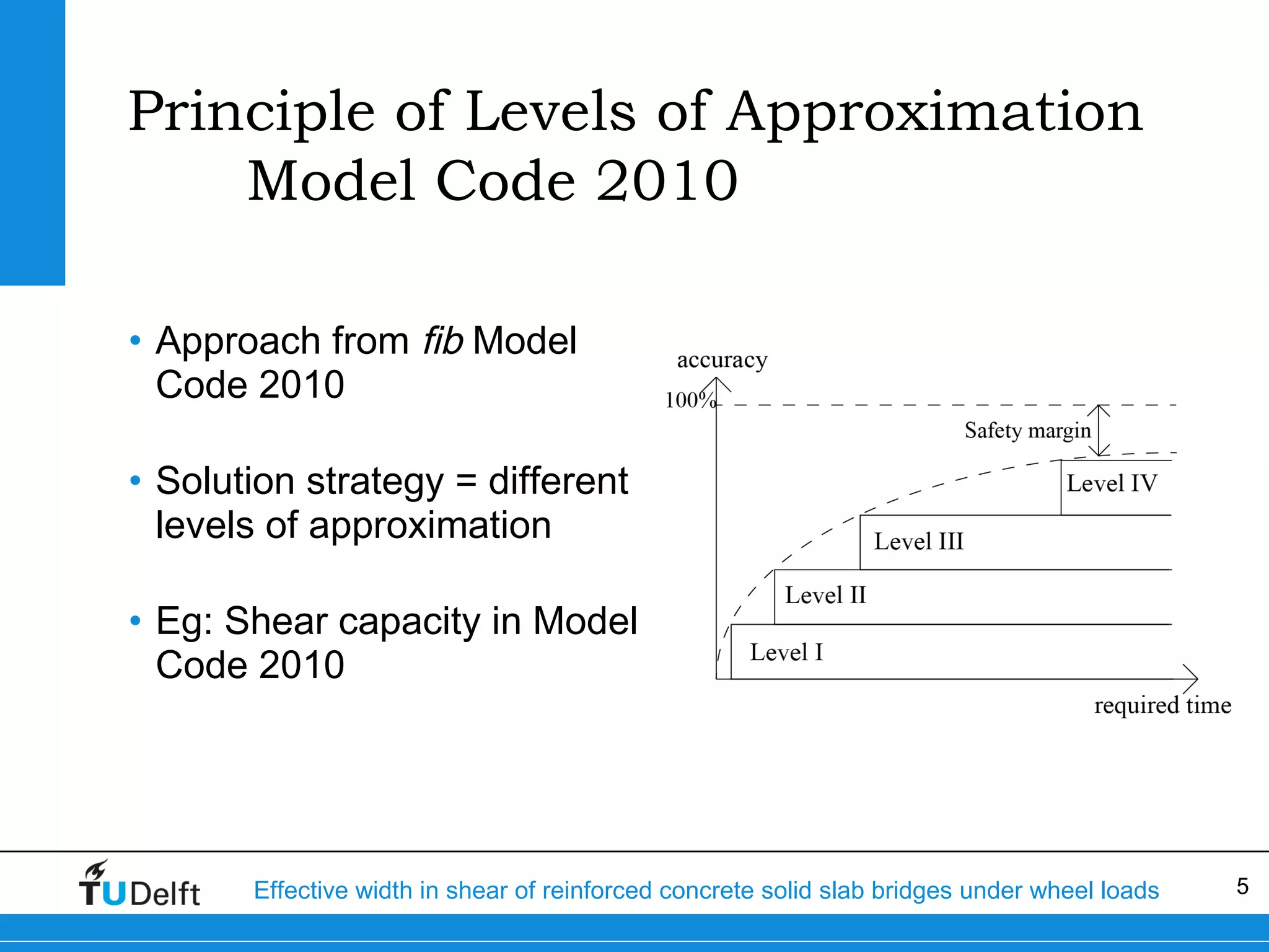
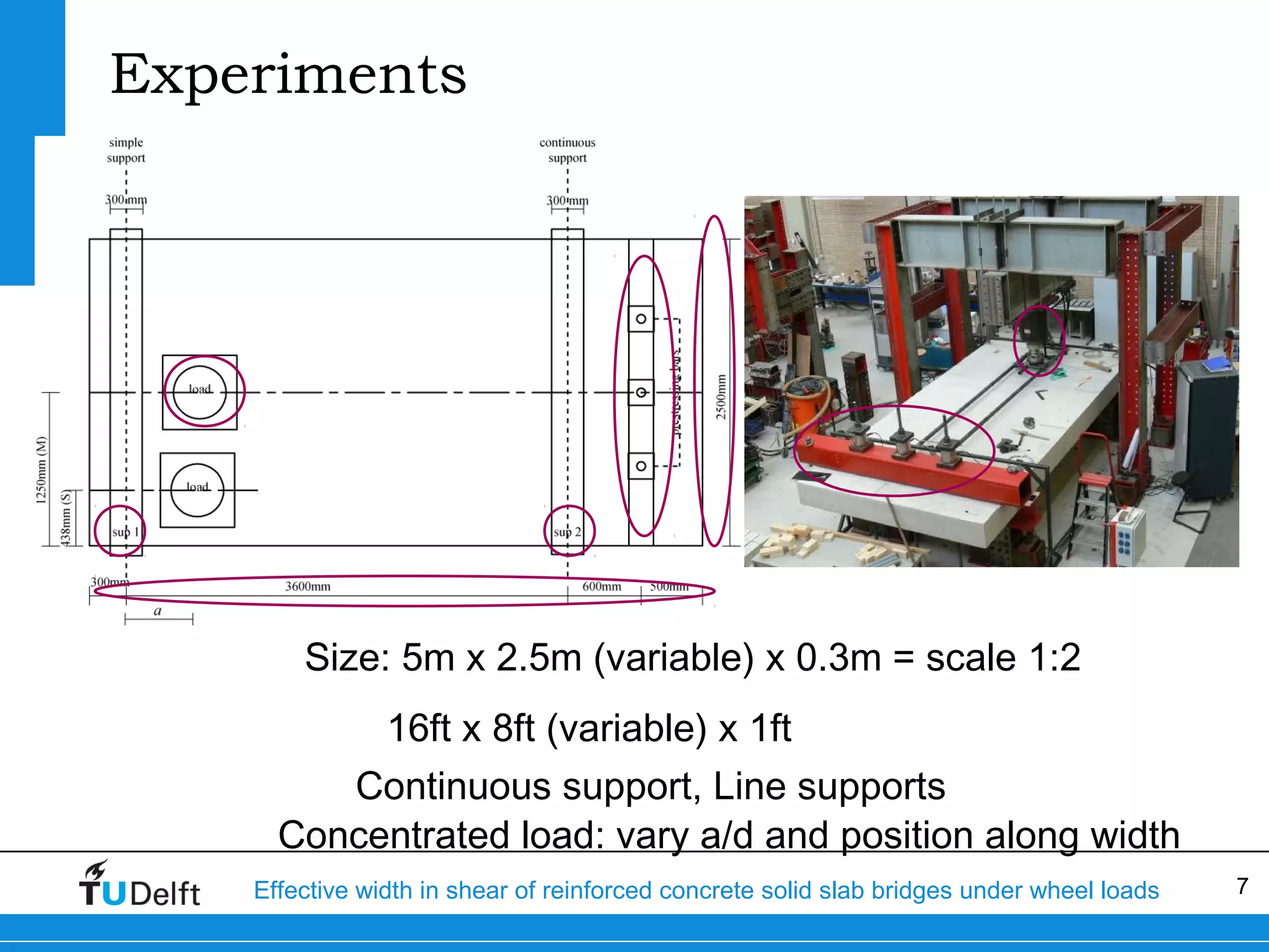
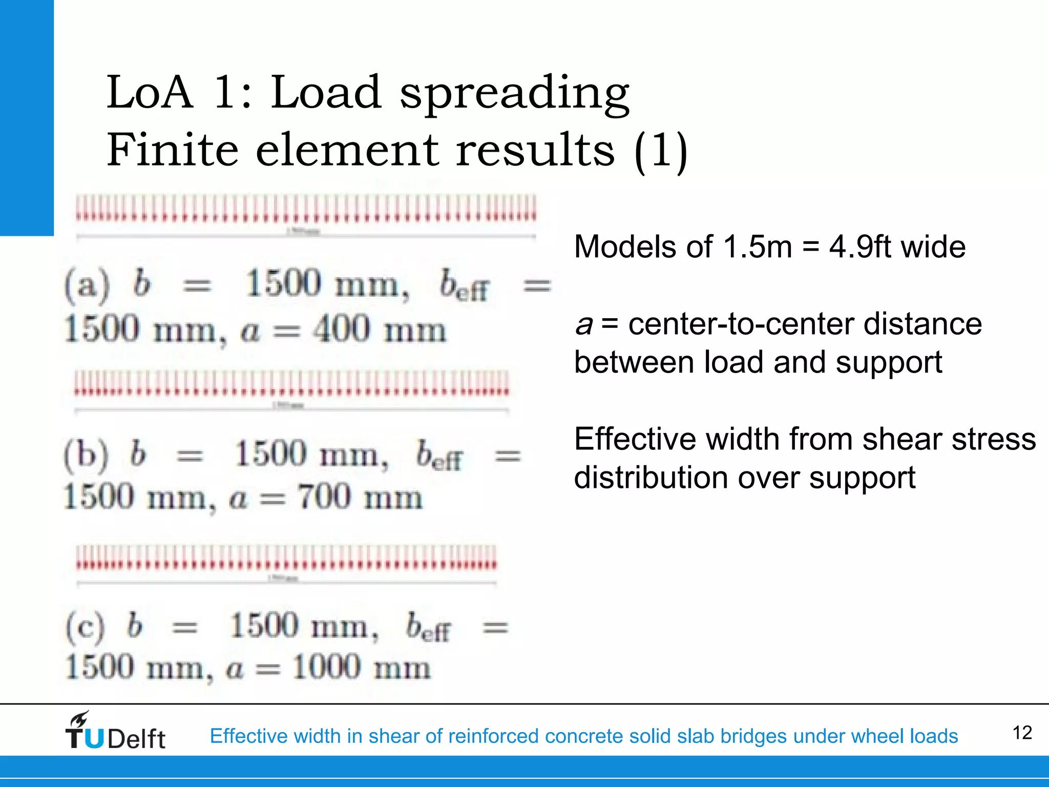
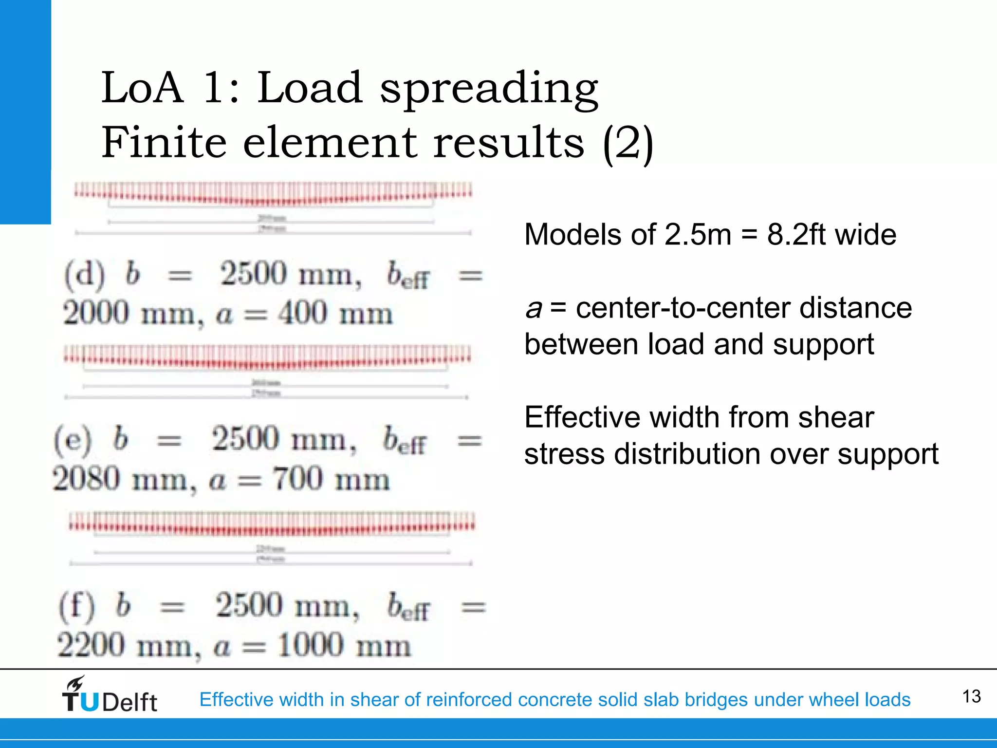
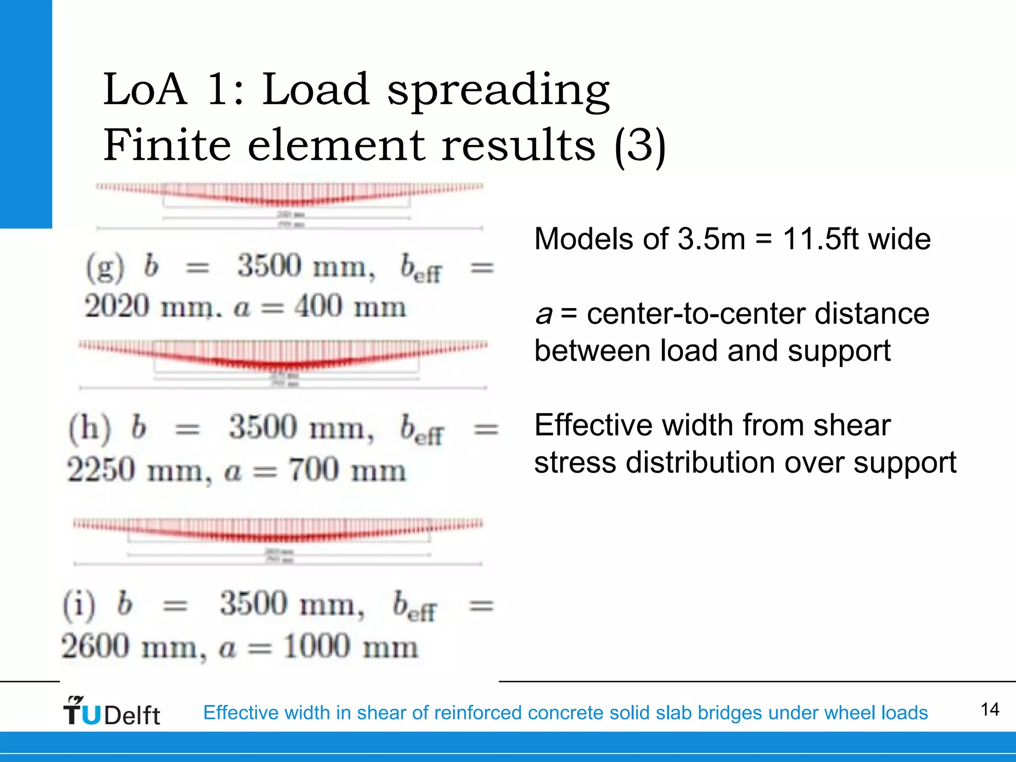
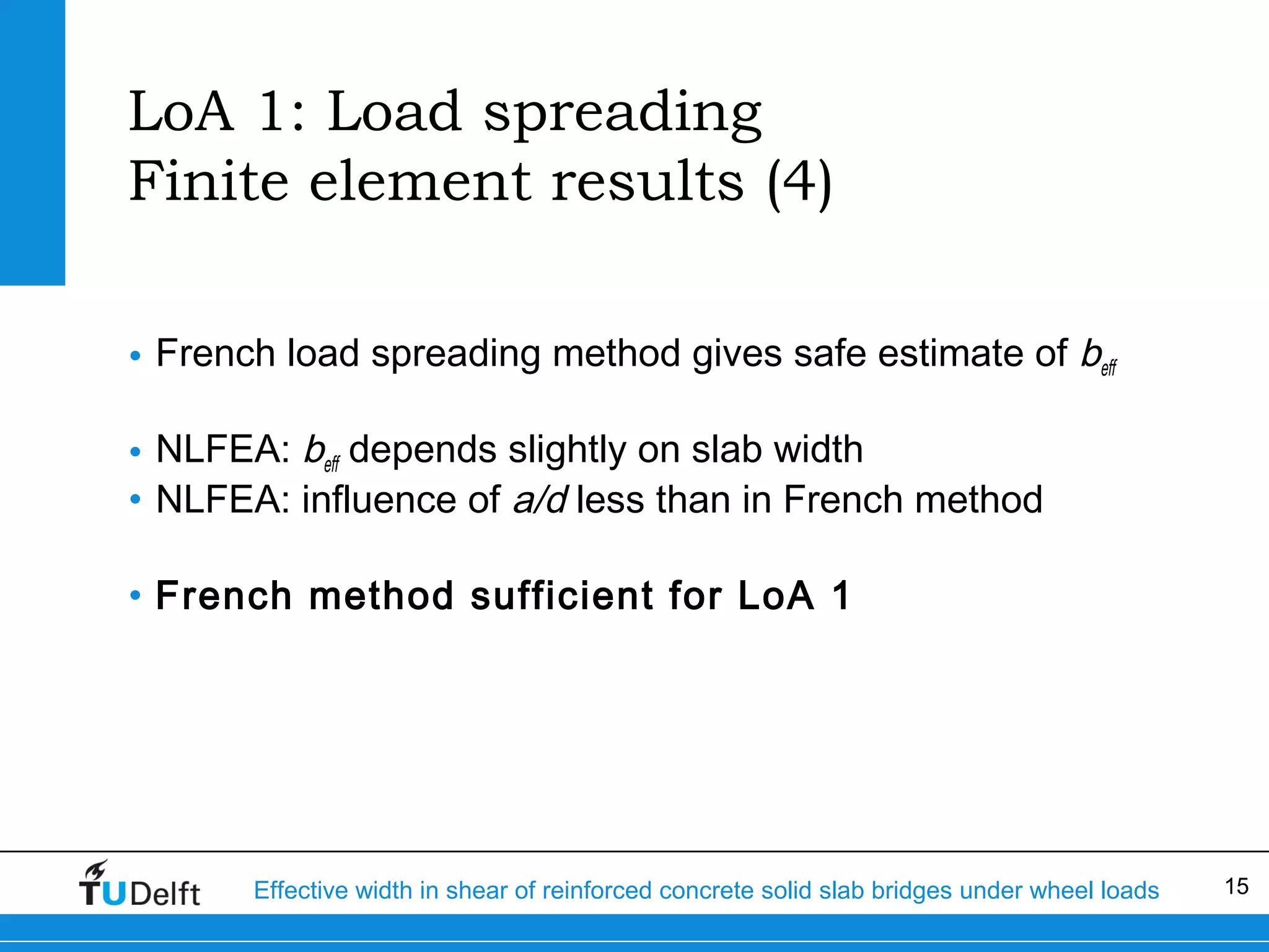
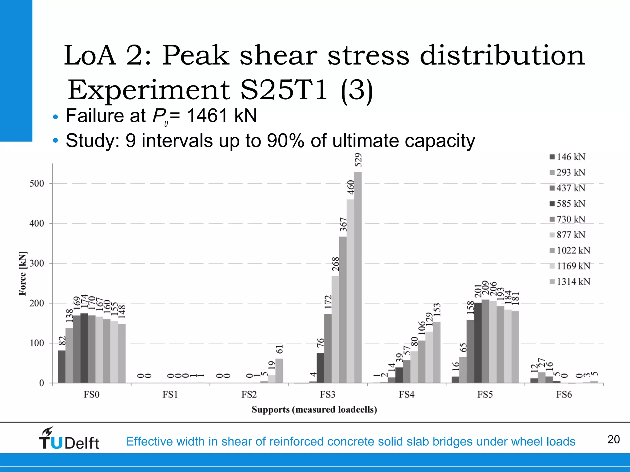
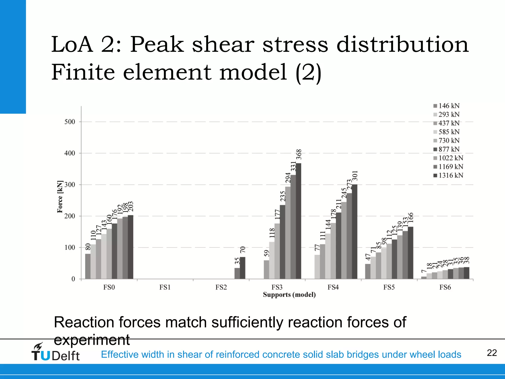
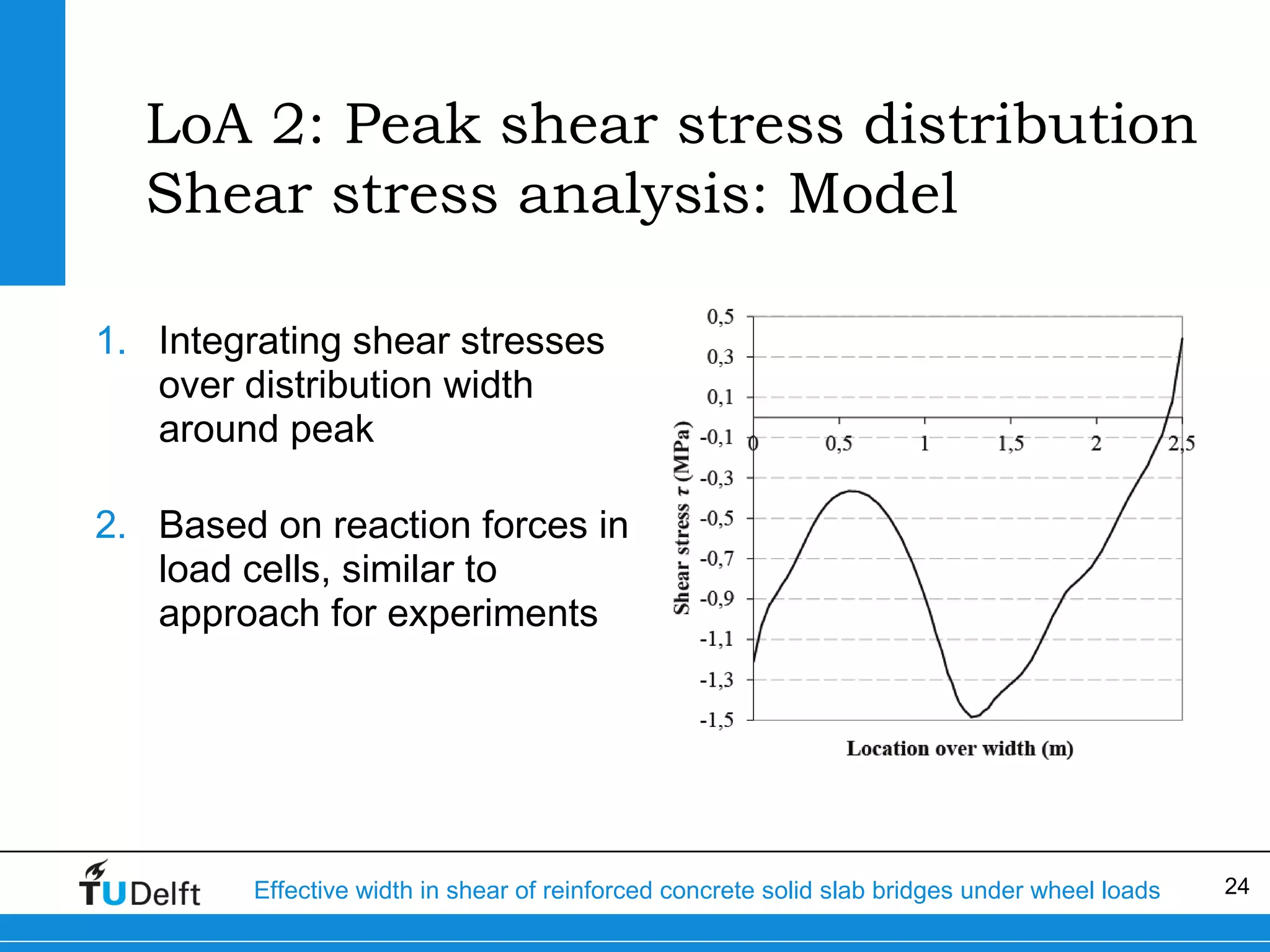
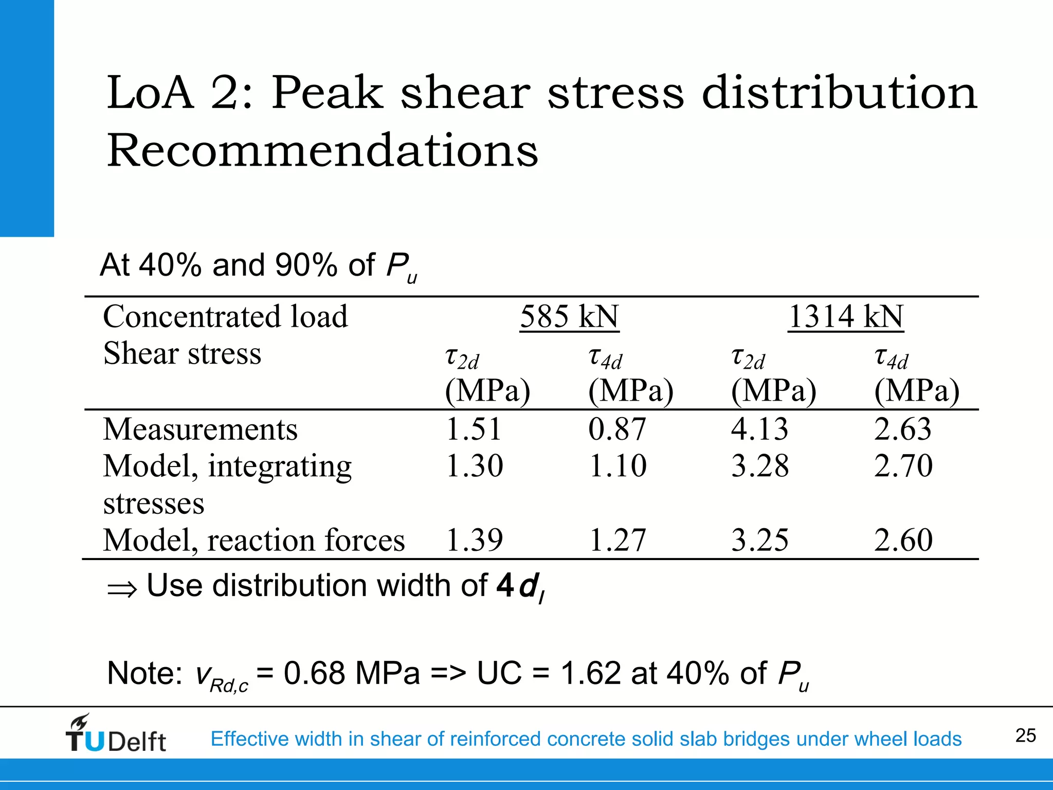
Effective width in shear
Of reinforced concrete solid slab bridges under
wheel loads
14-01-2014

Eva Lantsoght, Ane de Boer, Cor van der Veen, Joost Walraven

Delft
University of
Technology

Challenge the future
Overview

•
•
•
•
•
•
•

Introduction
Principle of Levels of Approximation
Experiments
LoA I: Load spreading
LoA II: Shear stress distribution
Case study
Summary

Effective width in shear of reinforced concrete solid slab bridges under wheel loads

2
Introduction
Problem Statement
Bridges from 60s and 70s

Increased live loads

heavy and long truck
(600 kN > perm. max = 50ton)
The Hague in 1959

End of service life + larger loads
Effective width in shear of reinforced concrete solid slab bridges under wheel loads

3
Introduction
Highway network in the Netherlands
• NL: 60% of bridges built before 1976
• Assessment: shear critical in 600
slab bridges

Highways in the Netherlands
Effective width in shear of reinforced concrete solid slab bridges under wheel loads

4
Principle of Levels of Approximation
Model Code 2010
• Approach from fib Model
Code 2010
• Solution strategy = different
levels of approximation
• Eg: Shear capacity in Model
Code 2010

Effective width in shear of reinforced concrete solid slab bridges under wheel loads

5
Principle of Levels of Approximation
Shear assessment
• Level I: Quick Scan sheet
• Fast, simple and conservative spreadsheet
• Unity check: loads/capacity

• Level II: Finite Element Analysis
• Shear stress distribution over support
• Peak shear stress: distribute over which width?

Effective width in shear of reinforced concrete solid slab bridges under wheel loads

6
Experiments

Size: 5m x 2.5m (variable) x 0.3m = scale 1:2
16ft x 8ft (variable) x 1ft
Continuous support, Line supports
Concentrated load: vary a/d and position along width
Effective width in shear of reinforced concrete solid slab bridges under wheel loads

7
LoA I: Load spreading
Effective width in shear

45° load spreading - Dutch practice

45° load spreading – French practice

Or: fixed value (eg. 1m = 3.3ft)
Effective width in shear of reinforced concrete solid slab bridges under wheel loads

8
LoA 1: Load spreading
Results of experiments

BS = 0.5m = 1.6 ft wide

BX = 2.0m = 6.6ft wide

Effective width in shear of reinforced concrete solid slab bridges under wheel loads

9
LoA 1: Load spreading
Results of experiments

0

500

1000

1500

b (mm)

2000

2500

Effective width in shear of reinforced concrete solid slab bridges under wheel loads

10
LoA 1: Load spreading
Statistical analysis
• Calculated from series vs. 45° load
spreading
• Comparison between database
(literature) + experiments and methods
• French load spreading method
underestimates less
• Lower COV for French load spreading
method
• Database: 63% vs 42%
• Delft experiments: 26% vs 22%

Effective width in shear of reinforced concrete solid slab bridges under wheel loads

11
LoA 1: Load spreading
Finite element results (1)
Models of 1.5m = 4.9ft wide

a = center-to-center distance
between load and support
Effective width from shear stress
distribution over support

Effective width in shear of reinforced concrete solid slab bridges under wheel loads

12
LoA 1: Load spreading
Finite element results (2)
Models of 2.5m = 8.2ft wide

a = center-to-center distance
between load and support
Effective width from shear
stress distribution over support

Effective width in shear of reinforced concrete solid slab bridges under wheel loads

13
LoA 1: Load spreading
Finite element results (3)
Models of 3.5m = 11.5ft wide

a = center-to-center distance
between load and support
Effective width from shear
stress distribution over support

Effective width in shear of reinforced concrete solid slab bridges under wheel loads

14
LoA 1: Load spreading
Finite element results (4)
• French load spreading method gives safe estimate of beff
• NLFEA: beff depends slightly on slab width
• NLFEA: influence of a/d less than in French method
• French method sufficient for LoA 1

Effective width in shear of reinforced concrete solid slab bridges under wheel loads

15
LoA 1: Load spreading
Application to slab bridges (1)
• Loading at edge
• Asymmetric effective width

Effective width in shear of reinforced concrete solid slab bridges under wheel loads

16
LoA 1: Load spreading
Application to slab bridges (2)

Effective width per axle instead of per wheel print
Effective width in shear of reinforced concrete solid slab bridges under wheel loads

17
LoA 2: Peak shear stress distribution
Experiment S25T1 (1)

Size: 5m x 2.5m x 0.3m = scale 1:2
Continuous support, line supports with load cells
Concentrated load
Effective width in shear of reinforced concrete solid slab bridges under wheel loads

18
LoA 2: Peak shear stress distribution
Experiment S25T1 (2)

Effective width in shear of reinforced concrete solid slab bridges under wheel loads

19
LoA 2: Peak shear stress distribution
Experiment S25T1 (3)

• Failure at Pu = 1461 kN
• Study: 9 intervals up to 90% of ultimate capacity

Effective width in shear of reinforced concrete solid slab bridges under wheel loads

20
LoA 2: Peak shear stress distribution
Finite element model
• TNO Diana
• Slab: shell elements
• Supports: solid elements
• Felt: interface elements
• 40% orthotropy assumed
• Phased activation of supports

Effective width in shear of reinforced concrete solid slab bridges under wheel loads

21
LoA 2: Peak shear stress distribution
Finite element model (2)

Reaction forces match sufficiently reaction forces of
experiment

Effective width in shear of reinforced concrete solid slab bridges under wheel loads

22
LoA 2: Peak shear stress distribution
Shear stress analysis: Experiment
• Assume force distributed
constantly per load cell
• Example: P = 1314 kN
• Total force over 2dl
86 mm
Ftot ,2 d = FS 3 +
( FS 2 + FS 4 ) = 580 kN
358 mm

• Resulting shear stress
τ 2d =

Ftot ,2 d
2d l 2

=

580 kN

2 ( 265 mm )

2

= 4.13 MPa

Effective width in shear of reinforced concrete solid slab bridges under wheel loads

23
LoA 2: Peak shear stress distribution
Shear stress analysis: Model
1. Integrating shear stresses
over distribution width
around peak
2. Based on reaction forces in
load cells, similar to
approach for experiments

Effective width in shear of reinforced concrete solid slab bridges under wheel loads

24
LoA 2: Peak shear stress distribution
Recommendations
At 40% and 90% of Pu

Concentrated load
Shear stress

585 kN
τ2d
τ4d
(MPa)
(MPa)
1.51
0.87
1.30
1.10

Measurements
Model, integrating
stresses
Model, reaction forces 1.39
⇒ Use distribution width of 4 d l

1.27

1314 kN
τ2d
τ4d
(MPa)
(MPa)
4.13
2.63
3.28
2.70
3.25

2.60

Note: vRd,c = 0.68 MPa => UC = 1.62 at 40% of Pu
Effective width in shear of reinforced concrete solid slab bridges under wheel loads

25
Case study
Introduction
• 4-span bridge
•
•
•
•

1959
End spans = 10.1m (33.1ft)
Mid spans = 14.4m (47.2ft)
Width = 10m (32.8ft), 6m (19.7ft) carries traffic

• QR24 reinforcement
• fy = 240MPa = 35ksi
• plain reinforcement
• fck = 35MPa = 5000psi
Effective width in shear of reinforced concrete solid slab bridges under wheel loads

26
Case Study
Results
• LoA 1

• vEd = 0.68MPa (99psi)
• vRd,c = 0.91MPa (132psi)
⇒UC = 0.74

• LoA 2:

• VEd = 278kN/m (19kip/ft)
• VRd,c = 438kN/m (30kip/ft)
⇒UC = 0.63

• LoA 1 more conservative than LoA 2
Effective width in shear of reinforced concrete solid slab bridges under wheel loads

27
Summary & Conclusions

1. Level I of Assessment: Quick Scan
method: French load spreading
method
2. Level II of Assessment: Finite
Element Model: Distribute peak
shear stress over 4dl
3. Case study: LoA 1 more
conservative than LoA 2
Effective width in shear of reinforced concrete solid slab bridges under wheel loads

28
Contact:
Eva Lantsoght
E.O.L.Lantsoght@tudelft.nl
+31(0)152787449
Effective width in shear of reinforced concrete solid slab bridges under wheel loads

29

Effective Width in Shear of Reinforced Concrete Solid Slab Bridges under Wheel Loads

  • 1.
    Effective width inshear Of reinforced concrete solid slab bridges under wheel loads 14-01-2014 Eva Lantsoght, Ane de Boer, Cor van der Veen, Joost Walraven Delft University of Technology Challenge the future
  • 2.
    Overview • • • • • • • Introduction Principle of Levelsof Approximation Experiments LoA I: Load spreading LoA II: Shear stress distribution Case study Summary Effective width in shear of reinforced concrete solid slab bridges under wheel loads 2
  • 3.
    Introduction Problem Statement Bridges from60s and 70s Increased live loads heavy and long truck (600 kN > perm. max = 50ton) The Hague in 1959 End of service life + larger loads Effective width in shear of reinforced concrete solid slab bridges under wheel loads 3
  • 4.
    Introduction Highway network inthe Netherlands • NL: 60% of bridges built before 1976 • Assessment: shear critical in 600 slab bridges Highways in the Netherlands Effective width in shear of reinforced concrete solid slab bridges under wheel loads 4
  • 5.
    Principle of Levelsof Approximation Model Code 2010 • Approach from fib Model Code 2010 • Solution strategy = different levels of approximation • Eg: Shear capacity in Model Code 2010 Effective width in shear of reinforced concrete solid slab bridges under wheel loads 5
  • 6.
    Principle of Levelsof Approximation Shear assessment • Level I: Quick Scan sheet • Fast, simple and conservative spreadsheet • Unity check: loads/capacity • Level II: Finite Element Analysis • Shear stress distribution over support • Peak shear stress: distribute over which width? Effective width in shear of reinforced concrete solid slab bridges under wheel loads 6
  • 7.
    Experiments Size: 5m x2.5m (variable) x 0.3m = scale 1:2 16ft x 8ft (variable) x 1ft Continuous support, Line supports Concentrated load: vary a/d and position along width Effective width in shear of reinforced concrete solid slab bridges under wheel loads 7
  • 8.
    LoA I: Loadspreading Effective width in shear 45° load spreading - Dutch practice 45° load spreading – French practice Or: fixed value (eg. 1m = 3.3ft) Effective width in shear of reinforced concrete solid slab bridges under wheel loads 8
  • 9.
    LoA 1: Loadspreading Results of experiments BS = 0.5m = 1.6 ft wide BX = 2.0m = 6.6ft wide Effective width in shear of reinforced concrete solid slab bridges under wheel loads 9
  • 10.
    LoA 1: Loadspreading Results of experiments 0 500 1000 1500 b (mm) 2000 2500 Effective width in shear of reinforced concrete solid slab bridges under wheel loads 10
  • 11.
    LoA 1: Loadspreading Statistical analysis • Calculated from series vs. 45° load spreading • Comparison between database (literature) + experiments and methods • French load spreading method underestimates less • Lower COV for French load spreading method • Database: 63% vs 42% • Delft experiments: 26% vs 22% Effective width in shear of reinforced concrete solid slab bridges under wheel loads 11
  • 12.
    LoA 1: Loadspreading Finite element results (1) Models of 1.5m = 4.9ft wide a = center-to-center distance between load and support Effective width from shear stress distribution over support Effective width in shear of reinforced concrete solid slab bridges under wheel loads 12
  • 13.
    LoA 1: Loadspreading Finite element results (2) Models of 2.5m = 8.2ft wide a = center-to-center distance between load and support Effective width from shear stress distribution over support Effective width in shear of reinforced concrete solid slab bridges under wheel loads 13
  • 14.
    LoA 1: Loadspreading Finite element results (3) Models of 3.5m = 11.5ft wide a = center-to-center distance between load and support Effective width from shear stress distribution over support Effective width in shear of reinforced concrete solid slab bridges under wheel loads 14
  • 15.
    LoA 1: Loadspreading Finite element results (4) • French load spreading method gives safe estimate of beff • NLFEA: beff depends slightly on slab width • NLFEA: influence of a/d less than in French method • French method sufficient for LoA 1 Effective width in shear of reinforced concrete solid slab bridges under wheel loads 15
  • 16.
    LoA 1: Loadspreading Application to slab bridges (1) • Loading at edge • Asymmetric effective width Effective width in shear of reinforced concrete solid slab bridges under wheel loads 16
  • 17.
    LoA 1: Loadspreading Application to slab bridges (2) Effective width per axle instead of per wheel print Effective width in shear of reinforced concrete solid slab bridges under wheel loads 17
  • 18.
    LoA 2: Peakshear stress distribution Experiment S25T1 (1) Size: 5m x 2.5m x 0.3m = scale 1:2 Continuous support, line supports with load cells Concentrated load Effective width in shear of reinforced concrete solid slab bridges under wheel loads 18
  • 19.
    LoA 2: Peakshear stress distribution Experiment S25T1 (2) Effective width in shear of reinforced concrete solid slab bridges under wheel loads 19
  • 20.
    LoA 2: Peakshear stress distribution Experiment S25T1 (3) • Failure at Pu = 1461 kN • Study: 9 intervals up to 90% of ultimate capacity Effective width in shear of reinforced concrete solid slab bridges under wheel loads 20
  • 21.
    LoA 2: Peakshear stress distribution Finite element model • TNO Diana • Slab: shell elements • Supports: solid elements • Felt: interface elements • 40% orthotropy assumed • Phased activation of supports Effective width in shear of reinforced concrete solid slab bridges under wheel loads 21
  • 22.
    LoA 2: Peakshear stress distribution Finite element model (2) Reaction forces match sufficiently reaction forces of experiment Effective width in shear of reinforced concrete solid slab bridges under wheel loads 22
  • 23.
    LoA 2: Peakshear stress distribution Shear stress analysis: Experiment • Assume force distributed constantly per load cell • Example: P = 1314 kN • Total force over 2dl 86 mm Ftot ,2 d = FS 3 + ( FS 2 + FS 4 ) = 580 kN 358 mm • Resulting shear stress τ 2d = Ftot ,2 d 2d l 2 = 580 kN 2 ( 265 mm ) 2 = 4.13 MPa Effective width in shear of reinforced concrete solid slab bridges under wheel loads 23
  • 24.
    LoA 2: Peakshear stress distribution Shear stress analysis: Model 1. Integrating shear stresses over distribution width around peak 2. Based on reaction forces in load cells, similar to approach for experiments Effective width in shear of reinforced concrete solid slab bridges under wheel loads 24
  • 25.
    LoA 2: Peakshear stress distribution Recommendations At 40% and 90% of Pu Concentrated load Shear stress 585 kN τ2d τ4d (MPa) (MPa) 1.51 0.87 1.30 1.10 Measurements Model, integrating stresses Model, reaction forces 1.39 ⇒ Use distribution width of 4 d l 1.27 1314 kN τ2d τ4d (MPa) (MPa) 4.13 2.63 3.28 2.70 3.25 2.60 Note: vRd,c = 0.68 MPa => UC = 1.62 at 40% of Pu Effective width in shear of reinforced concrete solid slab bridges under wheel loads 25
  • 26.
    Case study Introduction • 4-spanbridge • • • • 1959 End spans = 10.1m (33.1ft) Mid spans = 14.4m (47.2ft) Width = 10m (32.8ft), 6m (19.7ft) carries traffic • QR24 reinforcement • fy = 240MPa = 35ksi • plain reinforcement • fck = 35MPa = 5000psi Effective width in shear of reinforced concrete solid slab bridges under wheel loads 26
  • 27.
    Case Study Results • LoA1 • vEd = 0.68MPa (99psi) • vRd,c = 0.91MPa (132psi) ⇒UC = 0.74 • LoA 2: • VEd = 278kN/m (19kip/ft) • VRd,c = 438kN/m (30kip/ft) ⇒UC = 0.63 • LoA 1 more conservative than LoA 2 Effective width in shear of reinforced concrete solid slab bridges under wheel loads 27
  • 28.
    Summary & Conclusions 1.Level I of Assessment: Quick Scan method: French load spreading method 2. Level II of Assessment: Finite Element Model: Distribute peak shear stress over 4dl 3. Case study: LoA 1 more conservative than LoA 2 Effective width in shear of reinforced concrete solid slab bridges under wheel loads 28
  • 29.
    Contact: Eva Lantsoght E.O.L.Lantsoght@tudelft.nl +31(0)152787449 Effective widthin shear of reinforced concrete solid slab bridges under wheel loads 29