Downloaded 511 times


![vi
FOREWORD
The Canadian Institute of Steel Construction is a national industry organization representing the structural steel,
open-web steel joist and steel plate fabricating industries in Canada. Formed in 1930 and granted a Federal
FKDUWHU LQ WKH ,6 IXQFWLRQV DV D QRQSUR¿W RUJDQL]DWLRQ SURPRWLQJ WKH HI¿FLHQW DQG HFRQRPLF XVH RI
fabricated steel in construction.
As a member of the Canadian Steel Construction Council, the Institute has a general interest in all uses of steel
in construction. CISC works in close co-operation with the Steel Structures Education Foundation (SSEF) to
develop educational courses and programmes related to the design and construction of steel structures. The
CISC supports and actively participates in the work of the Standards Council of Canada, the Canadian Standards
Association, the Canadian Commission on Building and Fire Codes and numerous other organizations, in Canada
and other countries, involved in research work and the preparation of codes and standards.
Preparation of engineering plans is not a function of the CISC. The Institute does provide technical information
through its professional engineering staff, through the preparation and dissemination of publications, and through
the medium of seminars, courses, meetings, video tapes, and computer programs.Architects, engineers and others
interested in steel construction are encouraged to make use of CISC information services.
This publication has been prepared and published by the Canadian Institute of Steel Construction. It is an important
part of a continuing effort to provide current, practical, information to assist educators, designers, fabricators, and
others interested in the use of steel in construction.
Although no effort has been spared in an attempt to ensure that all data in this book is factual and that the
numerical values are accurate to a degree consistent with current structural design practice, the Canadian Institute
of Steel Construction, the author and his employer, Hatch, do not assume responsibility for errors or oversights
resulting from the use of the information contained herein. Anyone making use of the contents of this book
assumes all liability arising from such use. All suggestions for improvement of this publication will receive full
consideration for future printings.
CISC is located at
3760 14th
Avenue, Suite 200
Markham, Ontario, L3R 3T7
and may also be contacted via one or more of the following:
Telephone: 905-946-0864
Fax: 905-946-8574
Email: info@cisc-icca.ca
Website: www.cisc-icca.ca
Revisions
This Edition of the Design Guide supersedes all previous versions posted on the CISC website: www.cisc-icca.
ca. Future revisions to this Design Guide will be posted on this website. Users are encouraged to visit this website
periodically for updates.](https://image.slidesharecdn.com/guideforthedesignofcrane-supportingsteelstructures-ramaccrimmon-170302173625/75/Guide-for-the-design-of-crane-supporting-steel-structures-6-2048.jpg)


![11
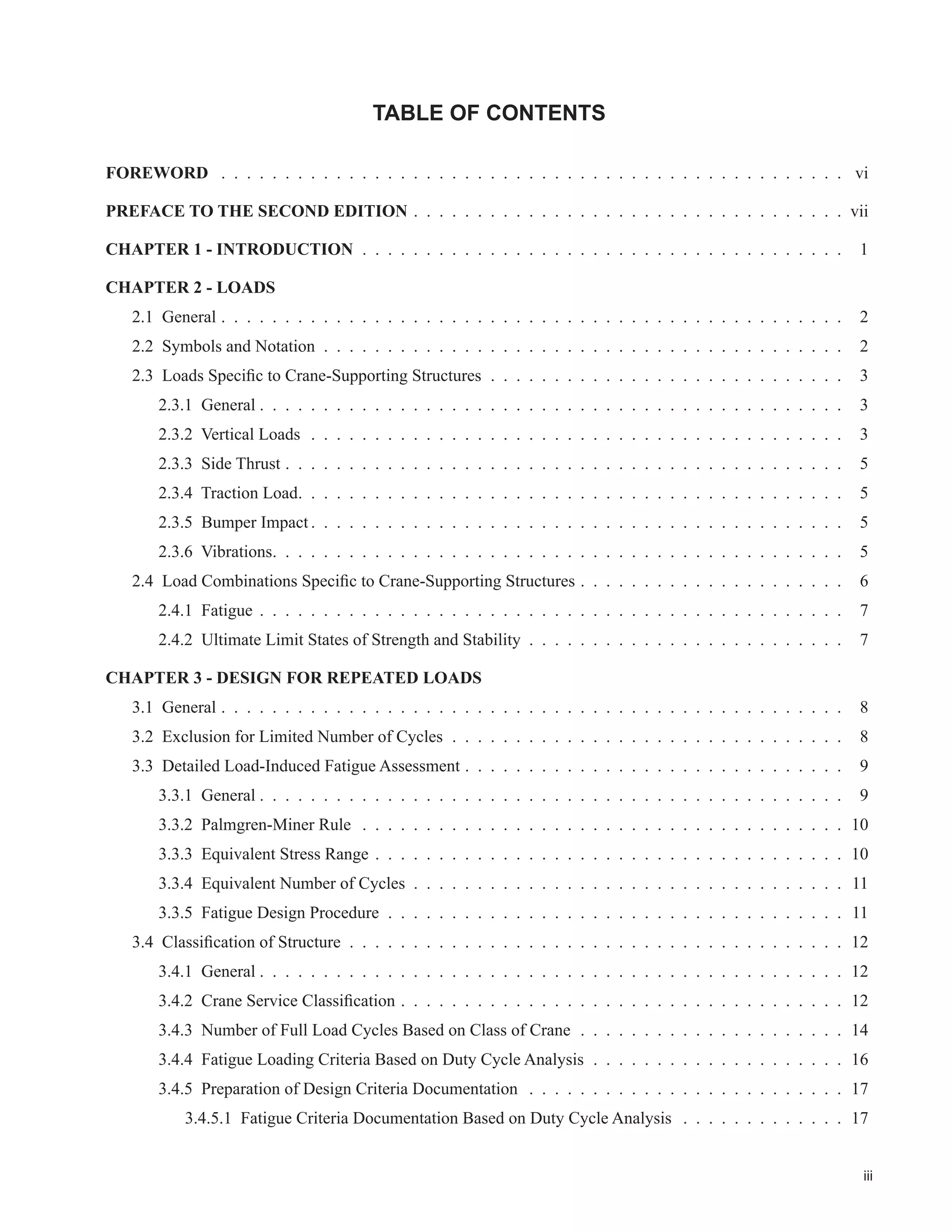
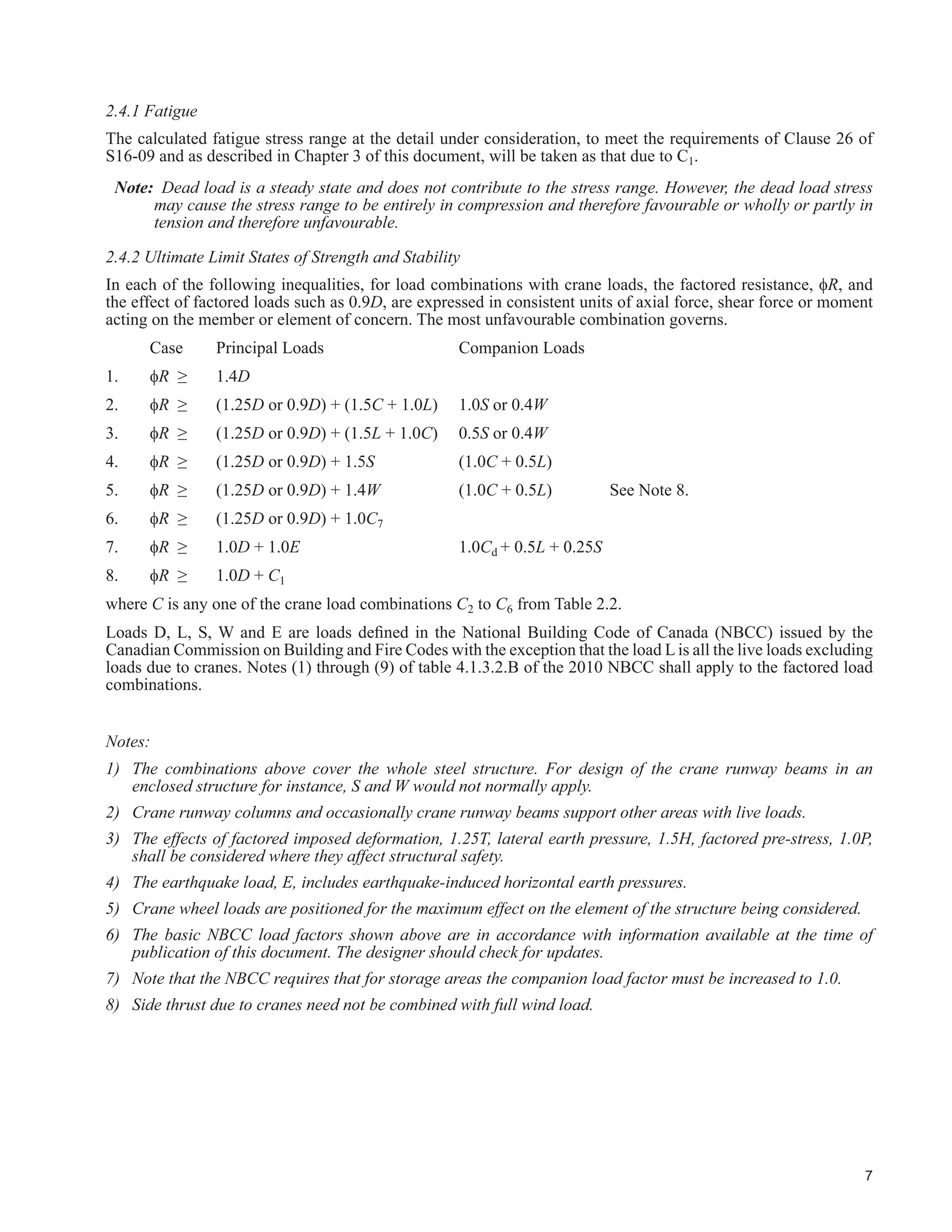
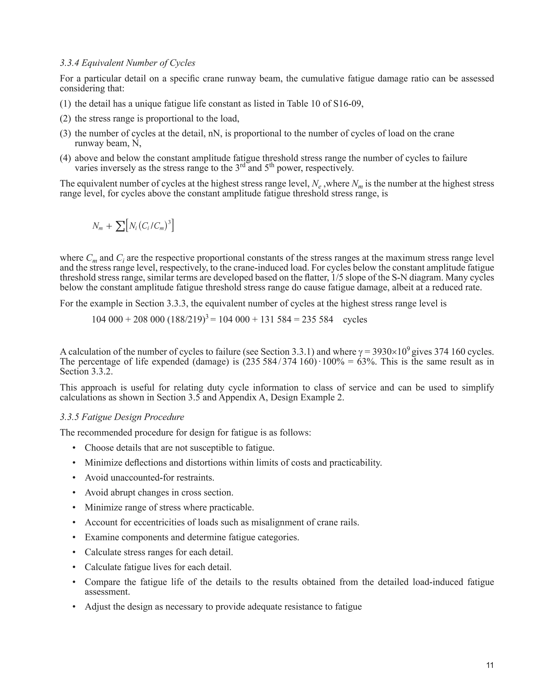
3.3.4 Equivalent Number of Cycles
)RU D SDUWLFXODU GHWDLO RQ D VSHFL¿F FUDQH UXQZD EHDP WKH FXPXODWLYH IDWLJXH GDPDJH UDWLR FDQ EH DVVHVVHG
considering that:
(1) the detail has a unique fatigue life constant as listed in Table 10 of S16-09,
(2) the stress range is proportional to the load,
(3) the number of cycles at the detail, nN, is proportional to the number of cycles of load on the crane
runway beam, N,
(4) above and below the constant amplitude fatigue threshold stress range the number of cycles to failure
varies inversely as the stress range to the 3rd
and 5th
power, respectively.
The equivalent number of cycles at the highest stress range level, Ne ,where Nm is the number at the highest stress
range level, for cycles above the constant amplitude fatigue threshold stress range, is
/N N C Cm i i m
3
+ ^ h8 B!
where Cm and Ci are the respective proportional constants of the stress ranges at the maximum stress range level
and the stress range level, respectively, to the crane-induced load. For cycles below the constant amplitude fatigue
WKUHVKROG VWUHVV UDQJH VLPLODU WHUPV DUH GHYHORSHG EDVHG RQ WKH ÀDWWHU VORSH RI WKH 61 GLDJUDP 0DQ FFOHV
below the constant amplitude fatigue threshold stress range do cause fatigue damage, albeit at a reduced rate.
For the example in Section 3.3.3, the equivalent number of cycles at the highest stress range level is
104 000 + 208 000 (188/219)3
= 104 000 + 131 584 = 235 584 cycles
A calculation of the number of cycles to failure (see Section 3.3.1) and where J = 3930u109
gives 374 160 cycles.
The percentage of life expended (damage) is (235 584/374 160)·100% = 63%. This is the same result as in
Section 3.3.2.
This approach is useful for relating duty cycle information to class of service and can be used to simplify
calculations as shown in Section 3.5 and Appendix A, Design Example 2.
3.3.5 Fatigue Design Procedure
The recommended procedure for design for fatigue is as follows:
‡ Choose details that are not susceptible to fatigue.
‡ 0LQLPL]H GHÀHFWLRQV DQG GLVWRUWLRQV ZLWKLQ OLPLWV RI FRVWV DQG SUDFWLFDELOLW
‡ Avoid unaccounted-for restraints.
‡ Avoid abrupt changes in cross section.
‡ Minimize range of stress where practicable.
‡ Account for eccentricities of loads such as misalignment of crane rails.
‡ Examine components and determine fatigue categories.
‡ Calculate stress ranges for each detail.
‡ Calculate fatigue lives for each detail.
‡ Compare the fatigue life of the details to the results obtained from the detailed load-induced fatigue
assessment.
‡ Adjust the design as necessary to provide adequate resistance to fatigue](https://image.slidesharecdn.com/guideforthedesignofcrane-supportingsteelstructures-ramaccrimmon-170302173625/75/Guide-for-the-design-of-crane-supporting-steel-structures-25-2048.jpg)
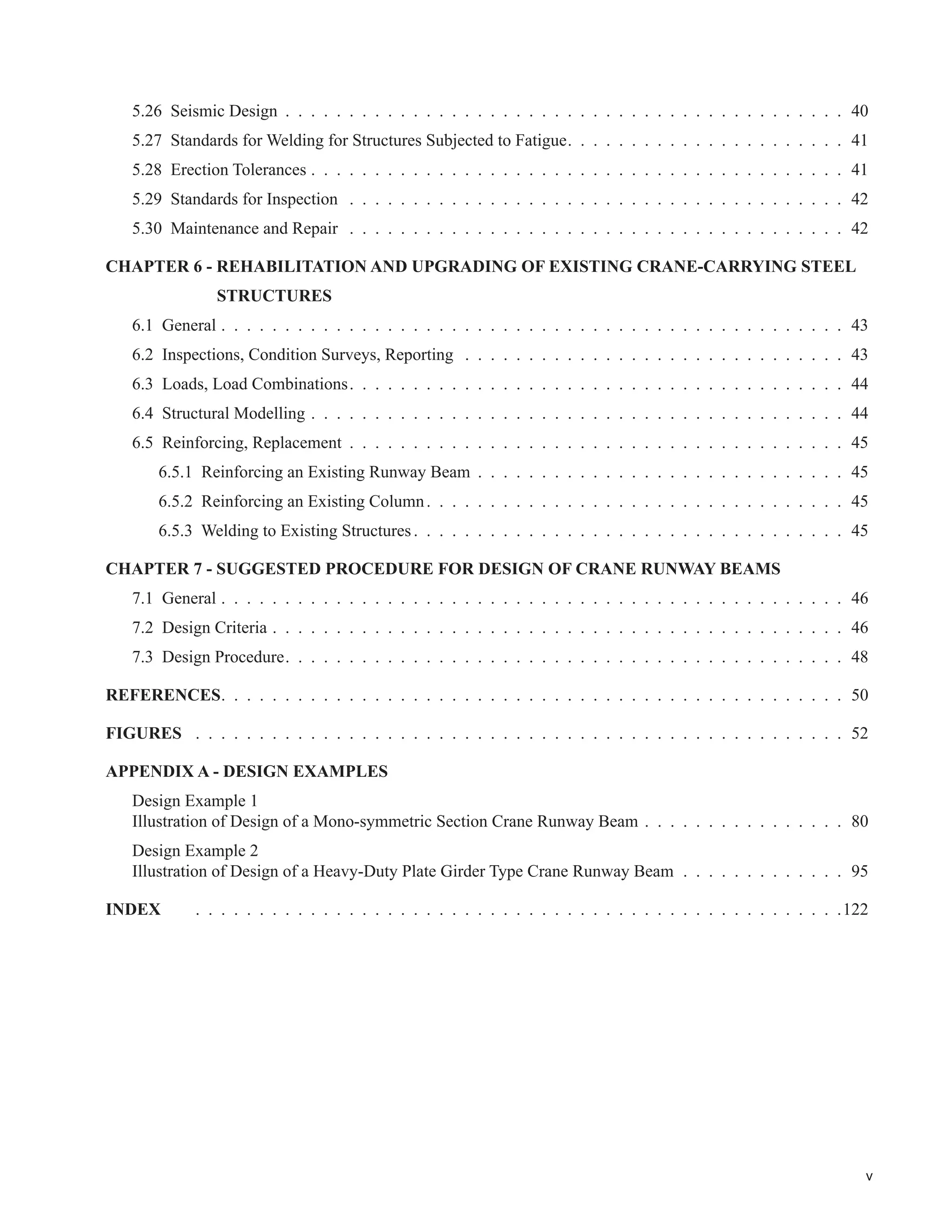
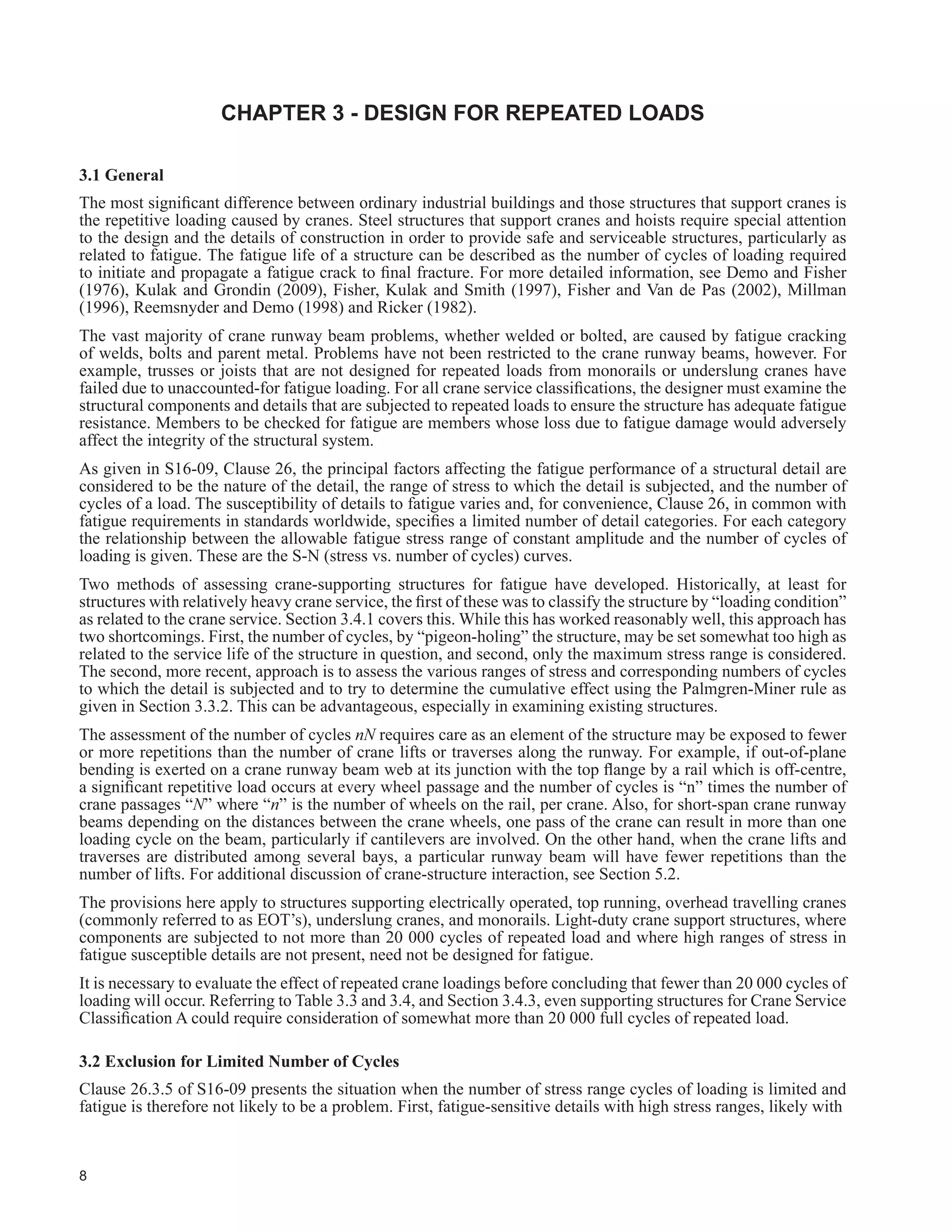
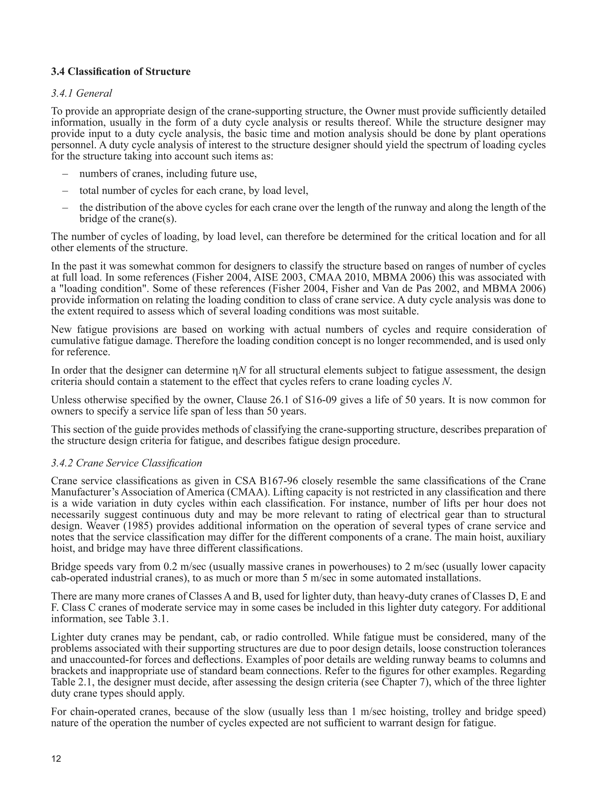
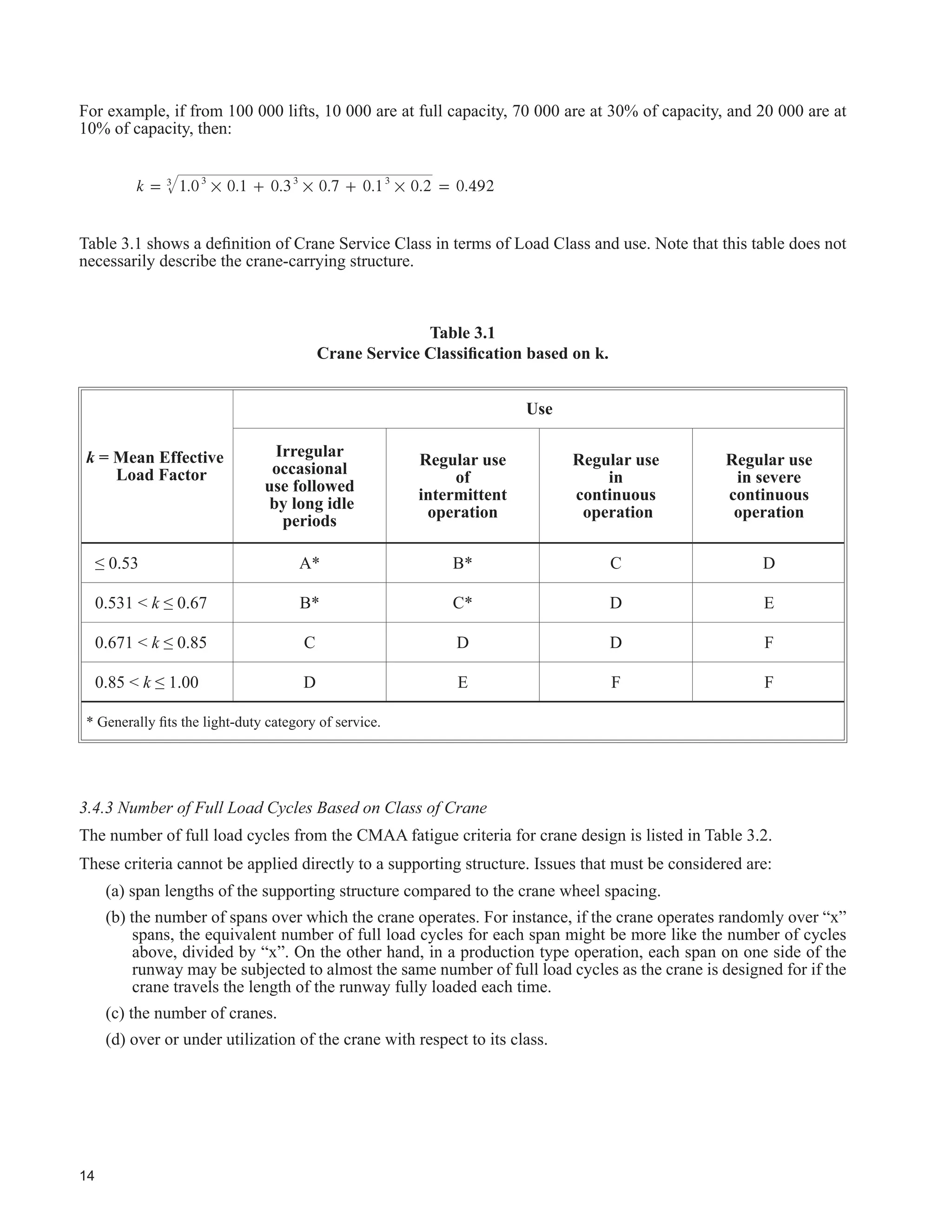
![OHDGV WR D PHDQ HIIHFWLYH ORDG
IDFWRU DSSOLHG WR WKH HTXLSPHQW DW D VSHFL¿HG IUHTXHQF 3URSHUO VL]HG FUDQH FRPSRQHQWV DUH VHOHFWHG EDVHG RQ
the mean effective load factor and use as given in Table 3.1 adapted from CMAA (2010).
From the load spectrum (CMAA 2010), the mean effective load factor is:
k W Pi i
3
3= !
where:
k = Mean effective load factor (used to establish crane service class only).
Wi = Load magnitude; expressed as a ratio of the lift load to the rated capacity. Lifts of the hoisting
gear without the lifted load must be included.
Pi = The ratio of cycles under the lift load magnitude condition to the total number of cycles.
Ȉ Pi = 1.0](https://image.slidesharecdn.com/guideforthedesignofcrane-supportingsteelstructures-ramaccrimmon-170302173625/75/Guide-for-the-design-of-crane-supporting-steel-structures-35-2048.jpg)


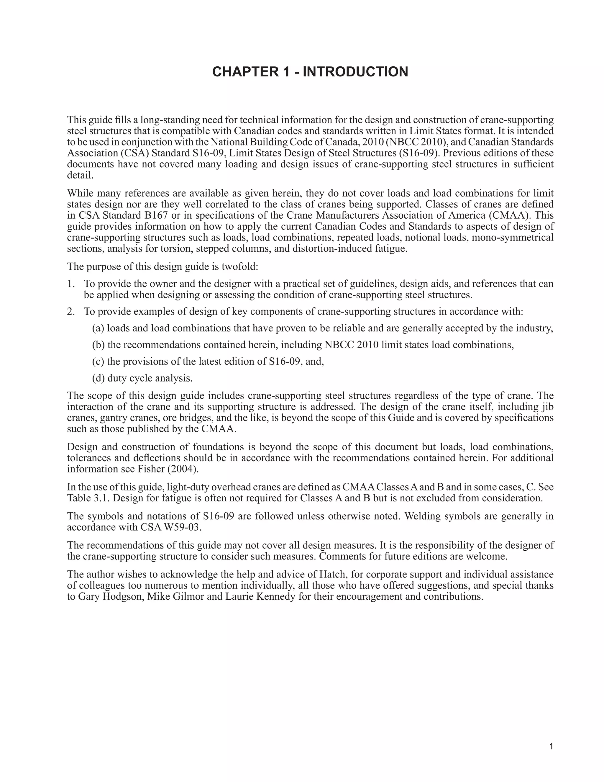
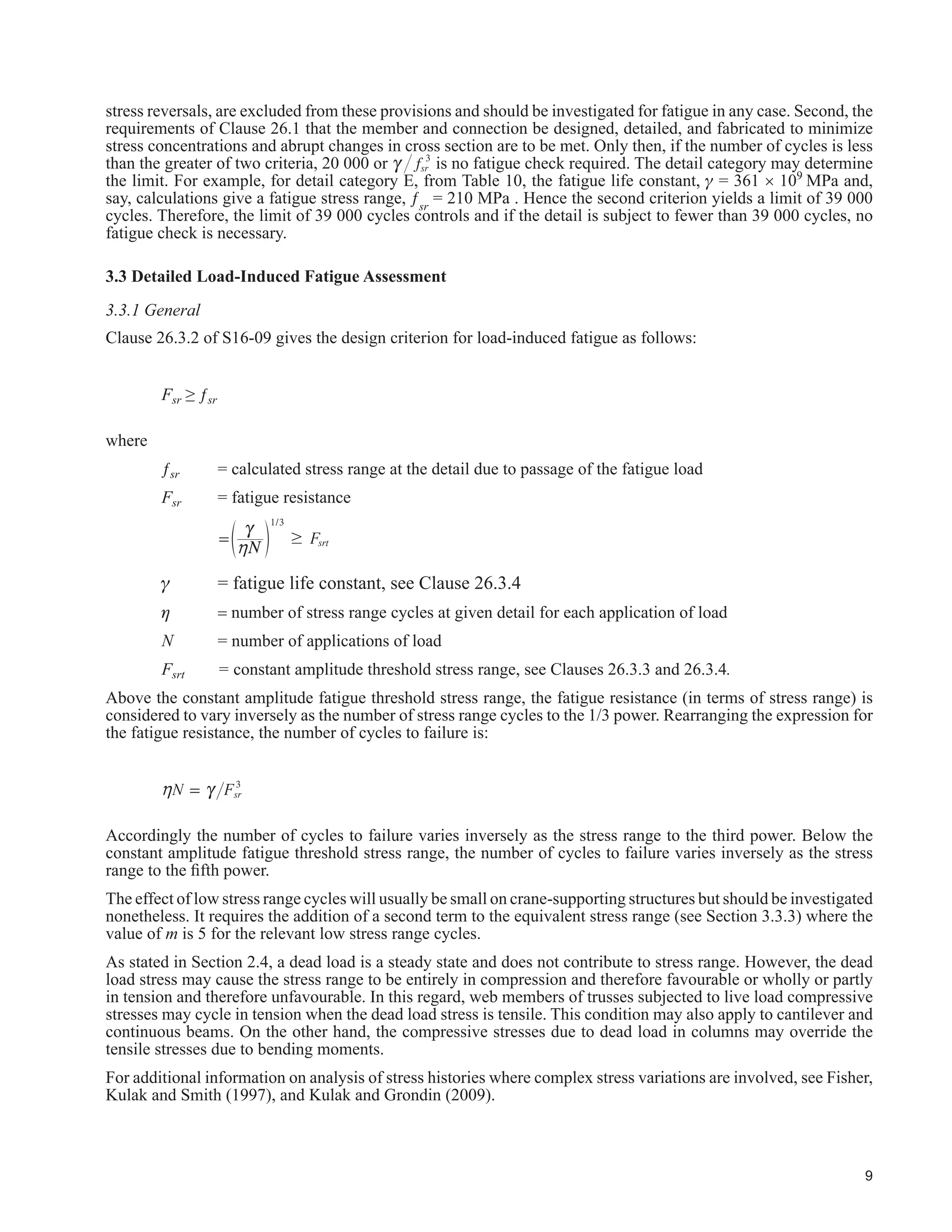
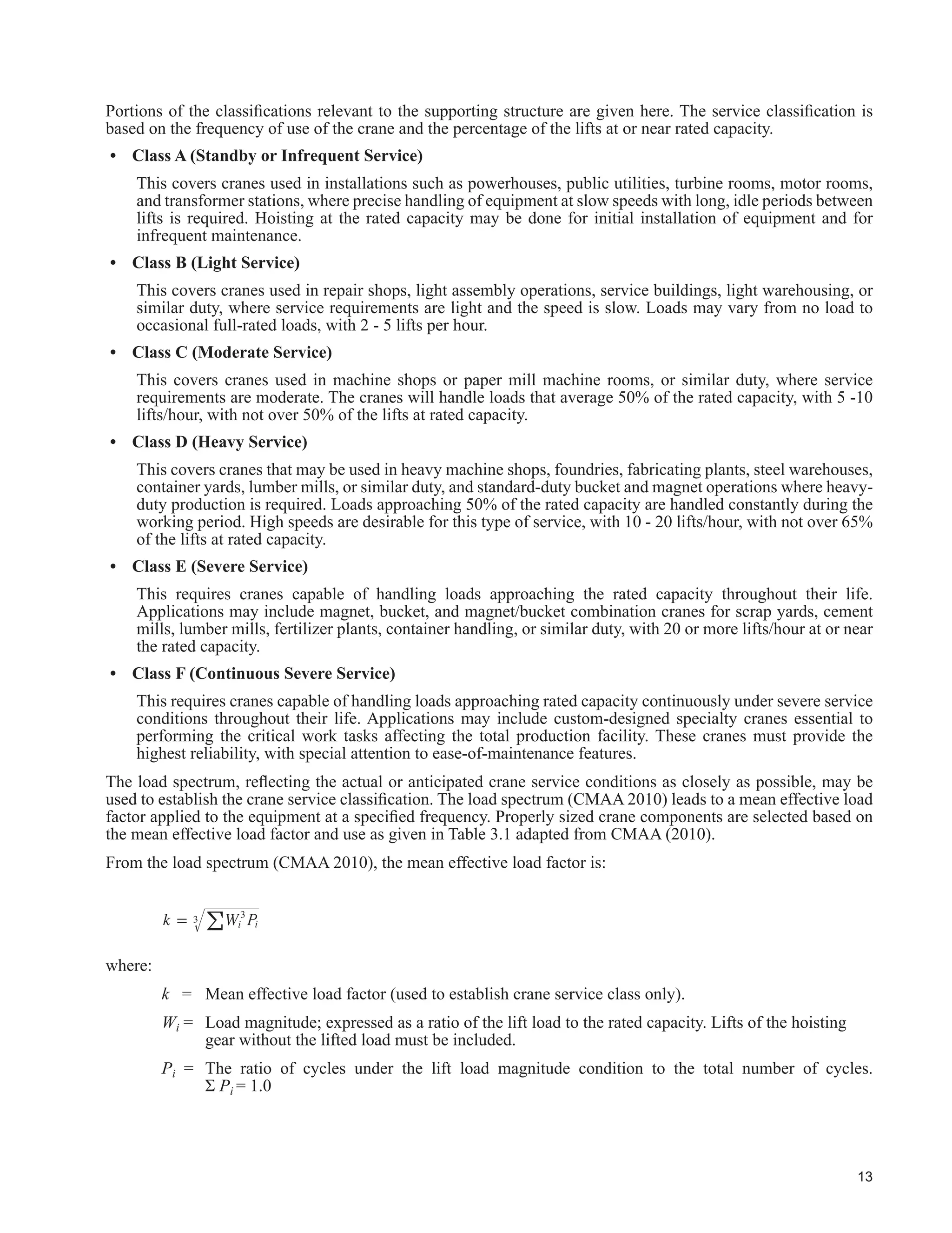
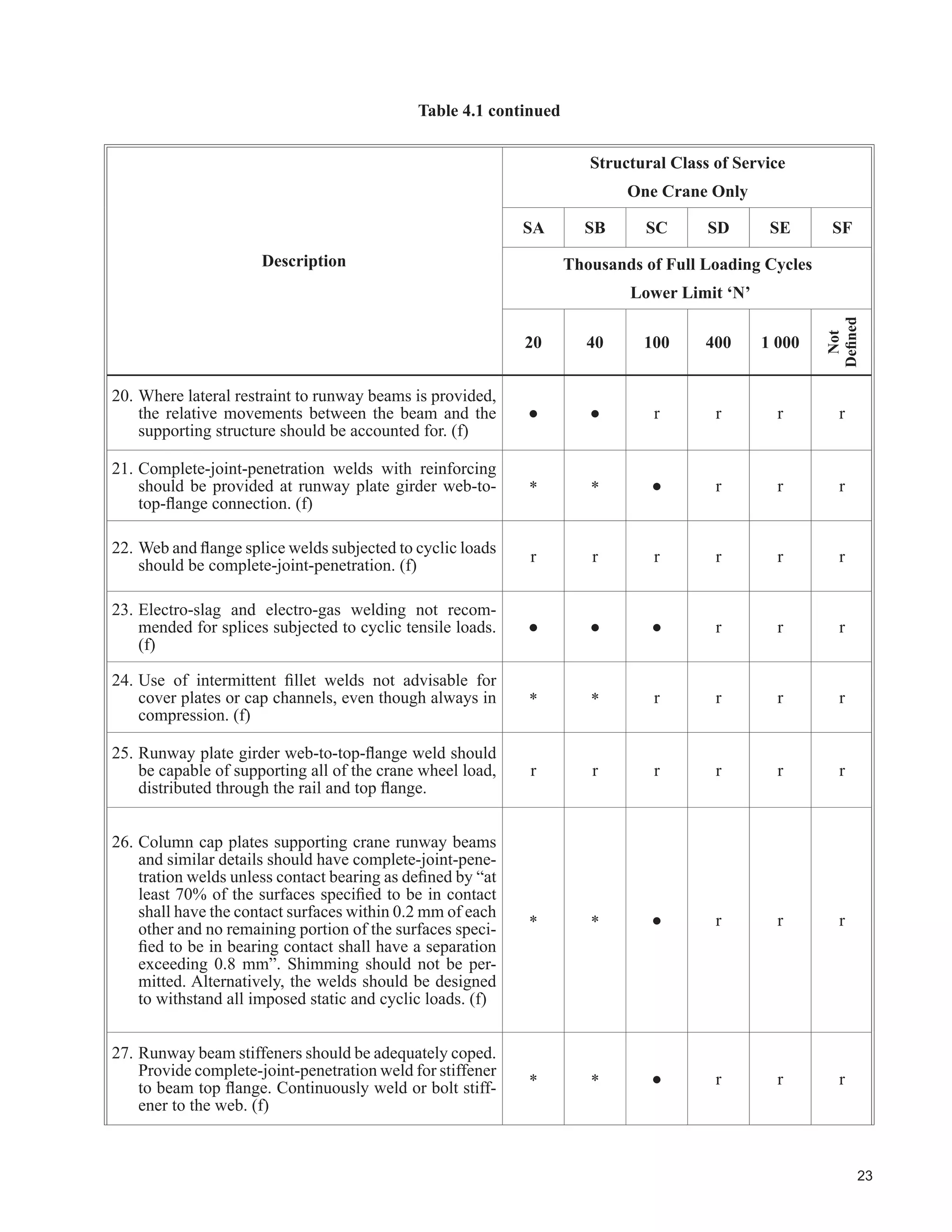
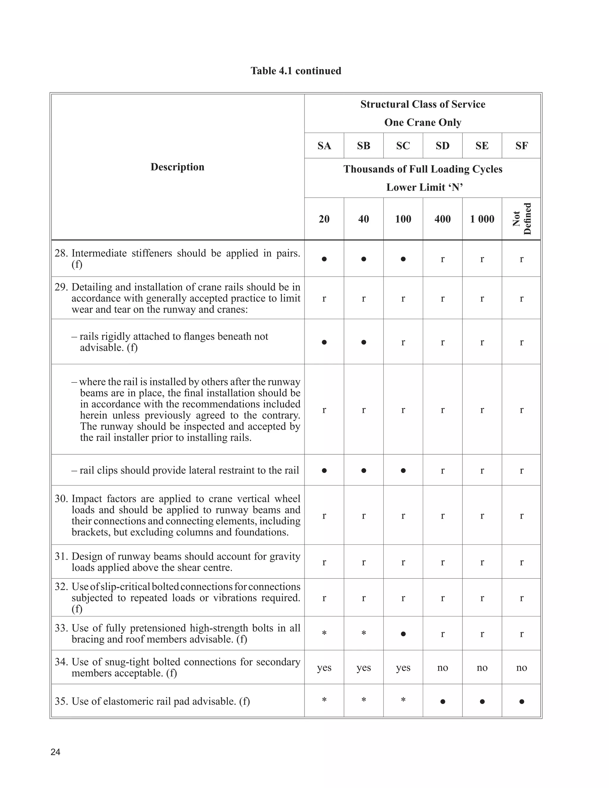
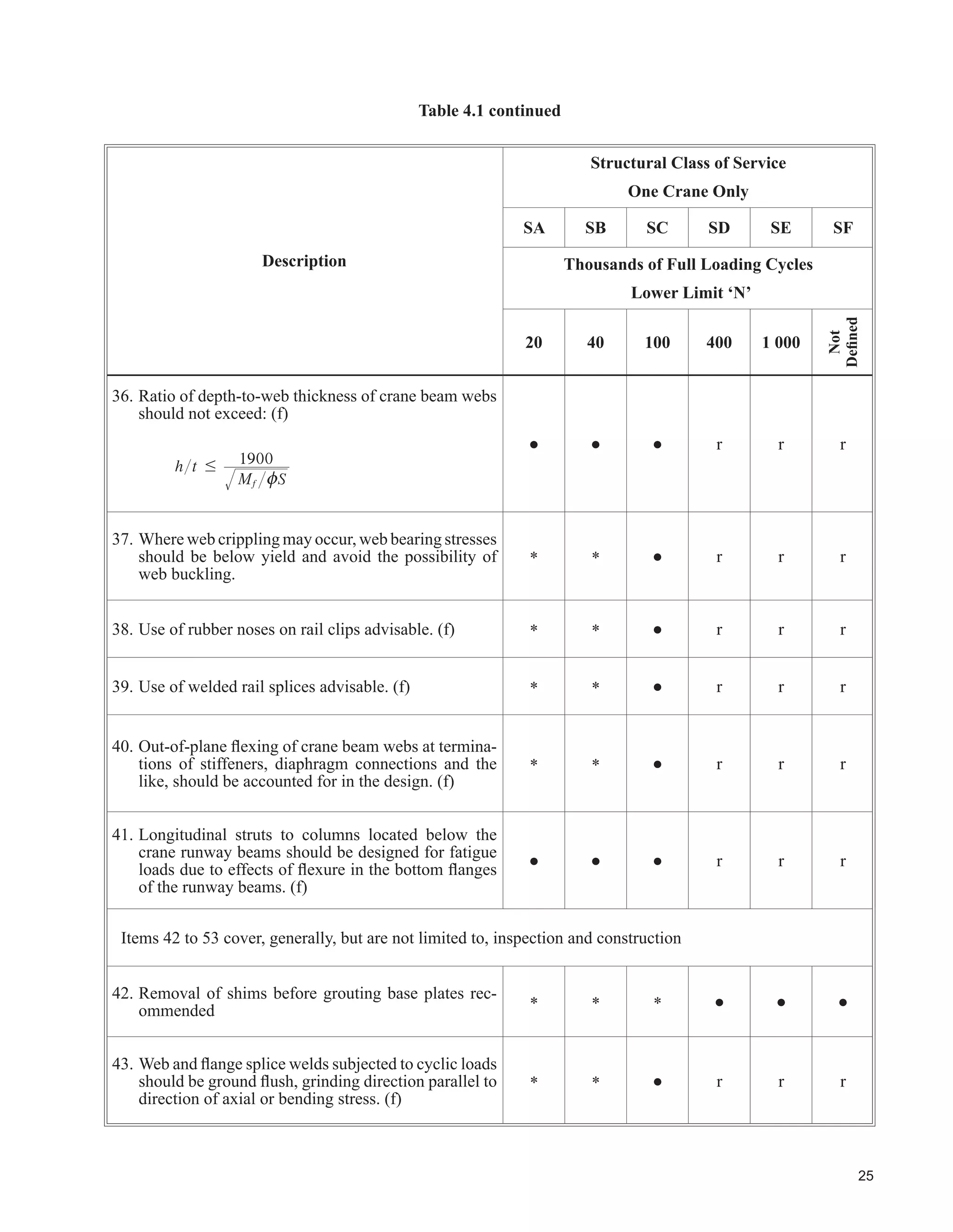
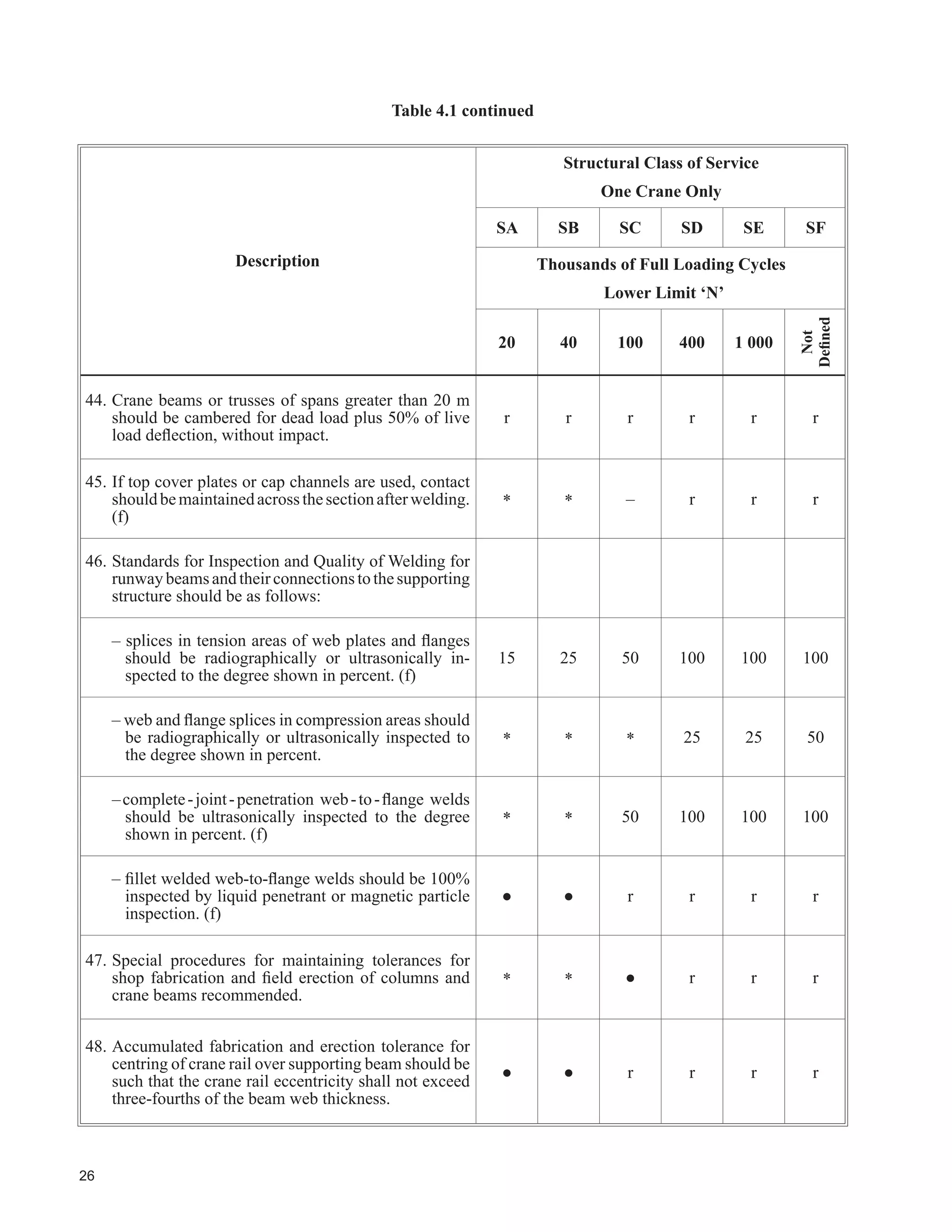
![22
7DEOH FRQWLQXHG
Description
6WUXFWXUDO ODVV RI 6HUYLFH
One Crane Only
SA SB SC SD SE SF
7KRXVDQGV RI )XOO /RDGLQJ FOHV
/RZHU /LPLW µ1¶
20 40 100 400 1 000
Not
'H¿QHG
12. Side thrust from cranes should be distributed in
proportion to the relative lateral stiffness of the
structures supporting the rails.
r r r r r r
13. Structural analysis should account for three-
dimensional effects such as distribution of crane-
induced lateral loads between building bents.
r r r r r r
9HUWLFDO GHÀHFWLRQ RI UXQZD EHDPV XQGHU VSHFL¿HG
crane loads, one crane only, not including impact,
should not exceed the indicated ratios of the span.
r
600
1
r
600
1
r
600
1
r
800
1
r
1000
1
r
1000
1
+RUL]RQWDO GHÀHFWLRQ RI UXQZD EHDPV XQGHU
VSHFL¿HG FUDQH ORDGV VKRXOG QRW H[FHHG WKH LQGLFDWHG
ratios of the span.
r
400
1
r
400
1
r
400
1
r
400
1
r
400
1
r
400
1
%XLOGLQJ IUDPH ODWHUDO GHÀHFWLRQ DW UXQZD EHDP
level from unfactored crane loads or from the
unfactored 1-in-10-yr wind load should not exceed
WKH VSHFL¿HG IUDFWLRQV RI WKH KHLJKW IURP FROXPQ
base plate or 50 mm, whichever is less.
r
240
1
r
240
1
r
240
1
r
400
1
r
400
1
r
400
1
Exceptions for pendant-operated cranes are noted: The lesser of 1/100 or 50 mm
5HODWLYH ODWHUDO GHÀHFWLRQ FKDQJH LQ JDXJH](https://image.slidesharecdn.com/guideforthedesignofcrane-supportingsteelstructures-ramaccrimmon-170302173625/75/Guide-for-the-design-of-crane-supporting-steel-structures-46-2048.jpg)
![29
7DEOH FRQWLQXHG
Item Comment
See
)LJXUH
13
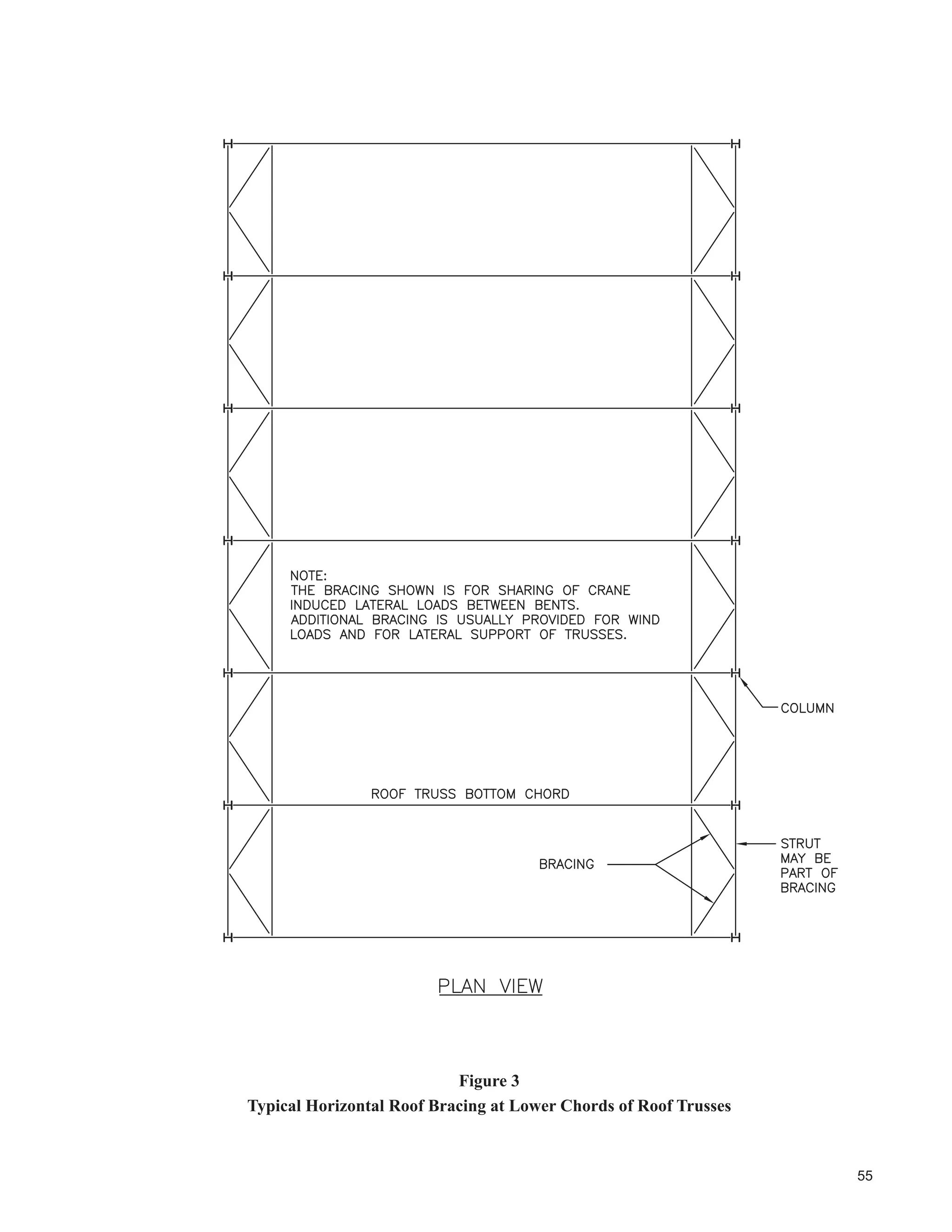
Some degree of three-dimensional analysis is required to adequately assess loads in hori-
zontal bracing. Refer to Fisher (2004) and Griggs (1976) for additional information.
3
14/15
5HFRPPHQGHG GHÀHFWLRQ OLPLWV IRU ,WHPV DQG DUH FRQVLVWHQW ZLWK WKH UHFRPPHQGDWLRQV
RI WKH 0$$ 'HÀHFWLRQV DUH HODVWLF EHDP GHÀHFWLRQV 'LIIHUHQWLDO VHWWOHPHQW RI IRXQGDWLRQV
can cause serious problems and should be limited to 12 mm unless special measures are
incorporated.
-
17
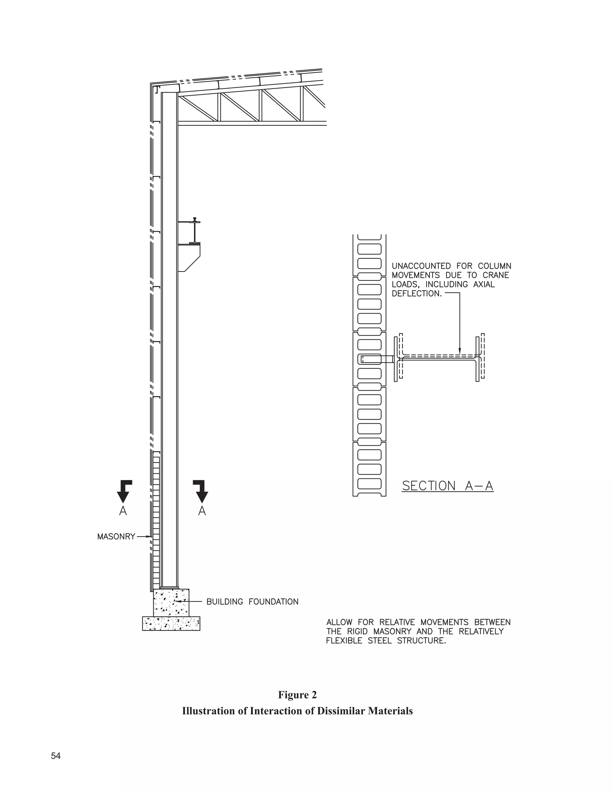
([FHVVLYHO ÀH[LEOH FROXPQV DQG URRI IUDPLQJ PHPEHUV FDQ UHVXOW LQ XQGHVLUDEOH FKDQJHV
in rail-to-rail distance, even under crane-induced gravity loads that cause sway of the
structure. These movements can create crane operational problems and unaccounted-for
lateral and torsional loads on the crane runway beams and their supports. Final runway
alignment should be left until after the full dead load of the roof is in place.
1
18
For applications where the ambient temperature range lies between +150°C and -30°C,
structural steel meeting the requirements of CSA G40.21 grade 350W can be expected to
perform adequately. For service at elevated temperatures, changes in properties of the steel
may warrant adjustment of design parameters. While notch toughness at low temperatures
is often required by bridge codes, this is not usually a requirement for crane runway beams,
one reason being the relatively small cost of replacement compared to a bridge beam.
-
19
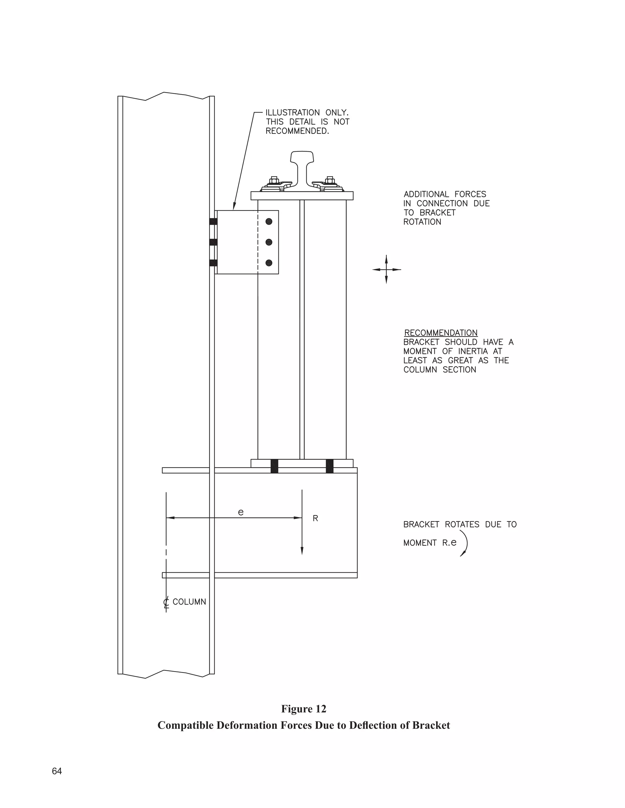
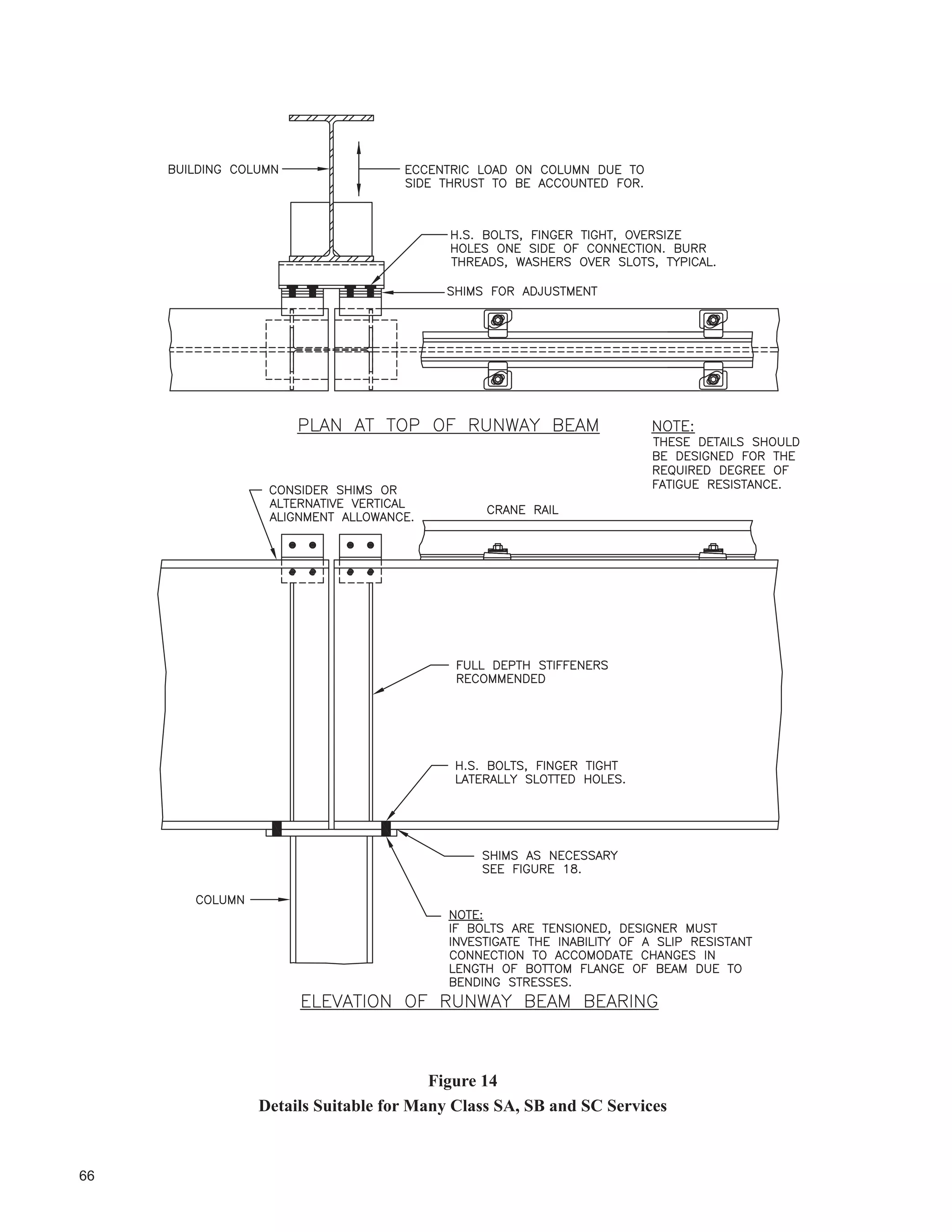
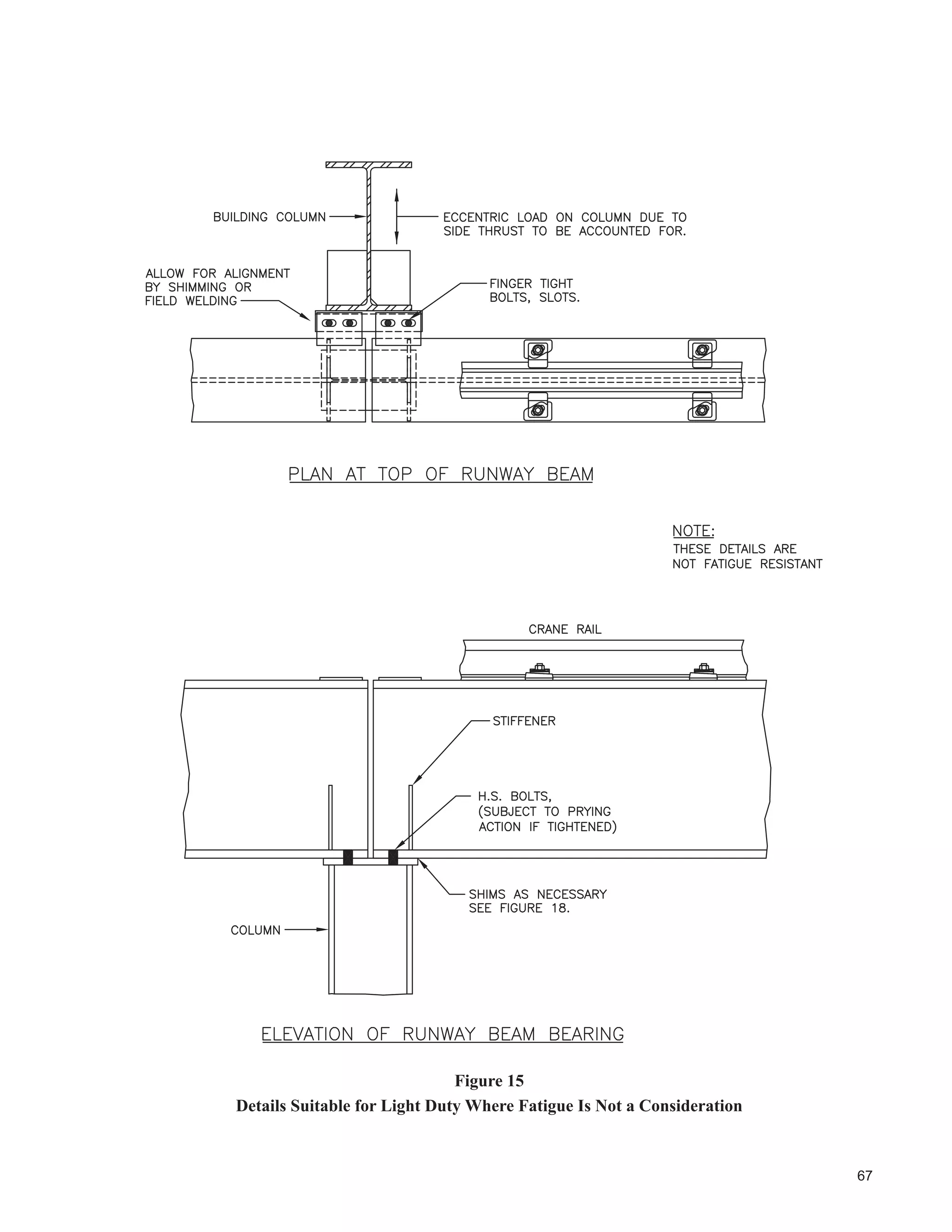
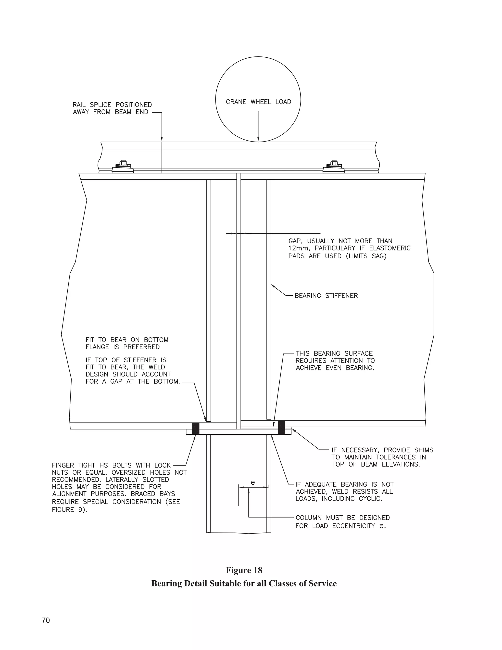
Limiting restraint to rotation and prying action on bolts can often be accommodated by
OLPLWLQJ GHÀHFWLRQV DQG E PRYLQJ WKH KROGGRZQ EROWV IURP EHWZHHQ WKH FROXPQ ÀDQJHV
to outside as shown in Figures 14 and 18. The cap plate thickness should be limited or use
RI ¿QJHU WLJKW EROWV LV UHFRPPHQGHG WR PLQLPL]H SULQJ DFWLRQ RQ WKH EROWV 1RWH WKDW WKH
eccentricity of vertical loads shown in Figure 18 may cause a state of tension in the column
ÀDQJHV )RU GHVLJQ IRU IDWLJXH ODUJH UDQJHV RI VWUHVV PD KDYH WR EH FRQVLGHUHG .QHH EUDFH
struts should not be used, in particular for class of service C, D, E and F.
9
14
15
18
20
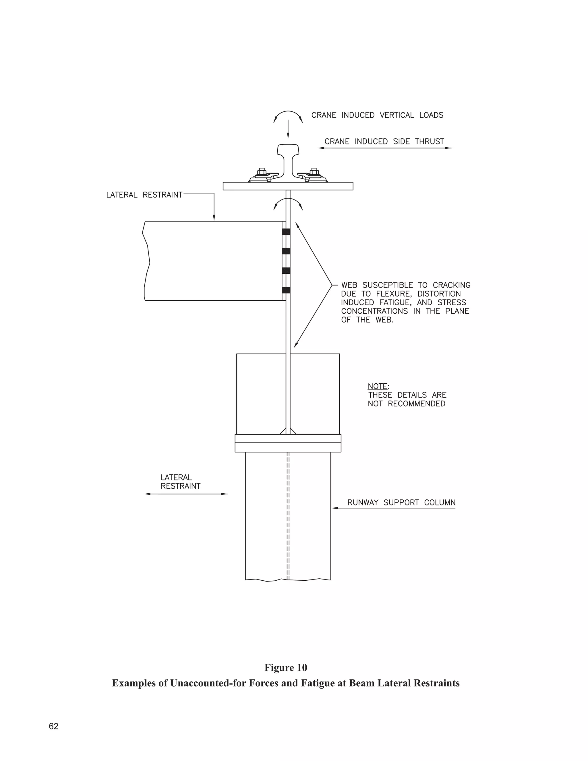
Where lateral restraint is not provided, the runway beams should be designed for bending
about both the strong and weak axes. See AISC (1993), Rowswell and Packer (1989),
and Rowswell (1987).The use of details that are rigid in out-of-plane directions should be
avoided. S16-01 requires consideration of the effects of distortion-induced fatigue.
13
14
15
16
21
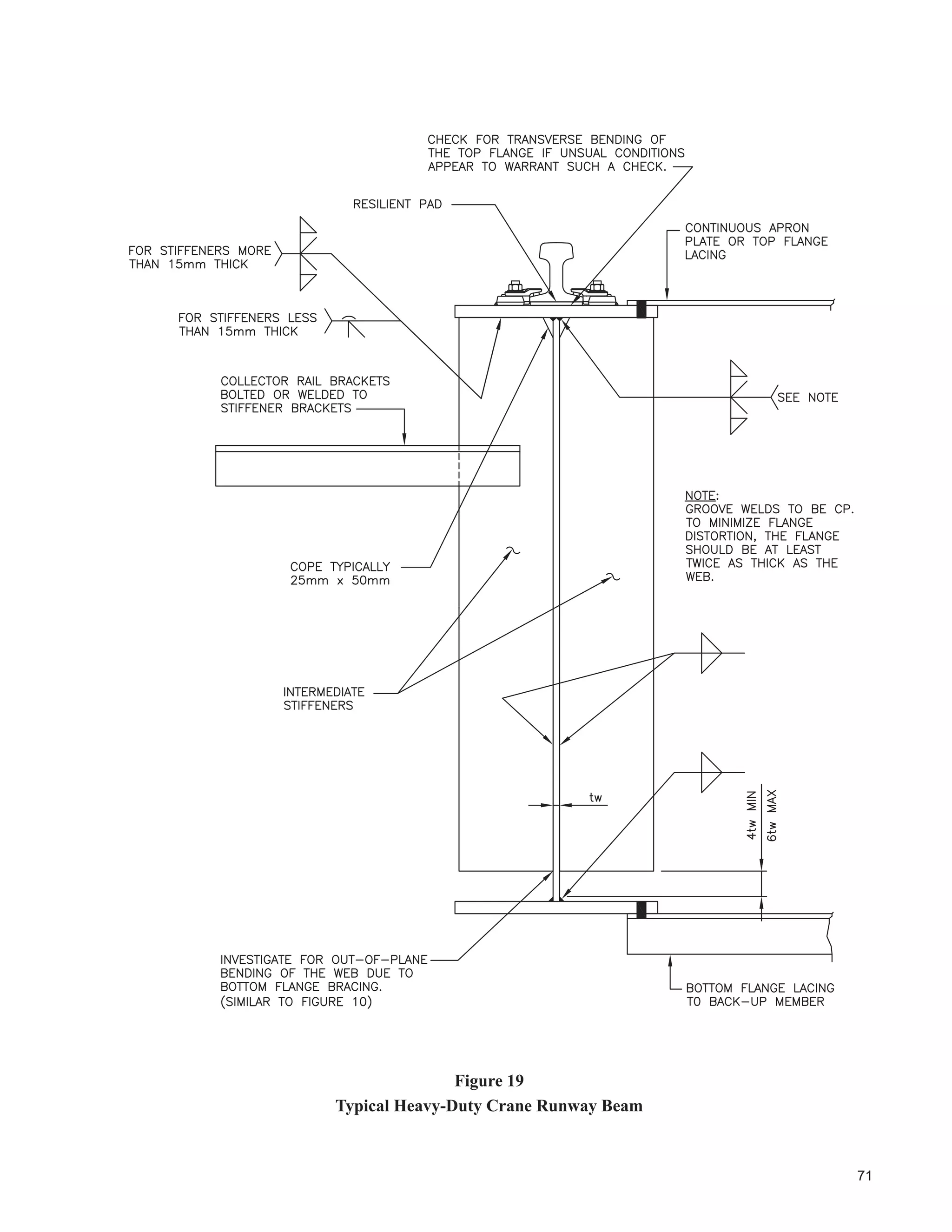
7KH ZHEWRÀDQJH ZHOG FDQ EH VXEMHFWHG WR WRUVLRQDO IRUFHV GXH WR ODWHUDO ORDGV DSSOLHG
DW WKH WRS RI WKH UDLO DQG UDLOWRÀDQJH FRQWDFW VXUIDFH QRW FHQWUHG RYHU WKH ZHE EHQHDWK
for instance. There is no directly applicable fatigue category. Refer to AISE (2003) for
additional information.
5
10
24
8VH RI LQWHUPLWWHQW ¿OOHW ZHOGV RQ WHQVLRQ DUHDV RI EXLOWXS UXQZD EHDPV LV SURKLELWHG
E 6$ : ,QWHUPLWWHQW ¿OOHW ZHOGV KDYH VKRZQ SRRU UHVLVWDQFH WR IDWLJXH DQG DUH
categorically not allowed on dynamically loaded structures by some authorities such as
AISE (2003) and AWS (1999). The use of these welds should be restricted to applications
where fatigue is not a consideration.
-](https://image.slidesharecdn.com/guideforthedesignofcrane-supportingsteelstructures-ramaccrimmon-170302173625/75/Guide-for-the-design-of-crane-supporting-steel-structures-55-2048.jpg)


![39
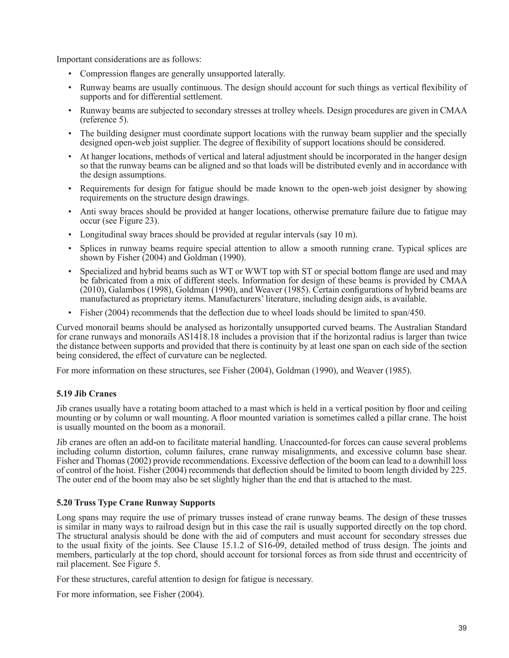
Important considerations are as follows:
‡ RPSUHVVLRQ ÀDQJHV DUH JHQHUDOO XQVXSSRUWHG ODWHUDOO
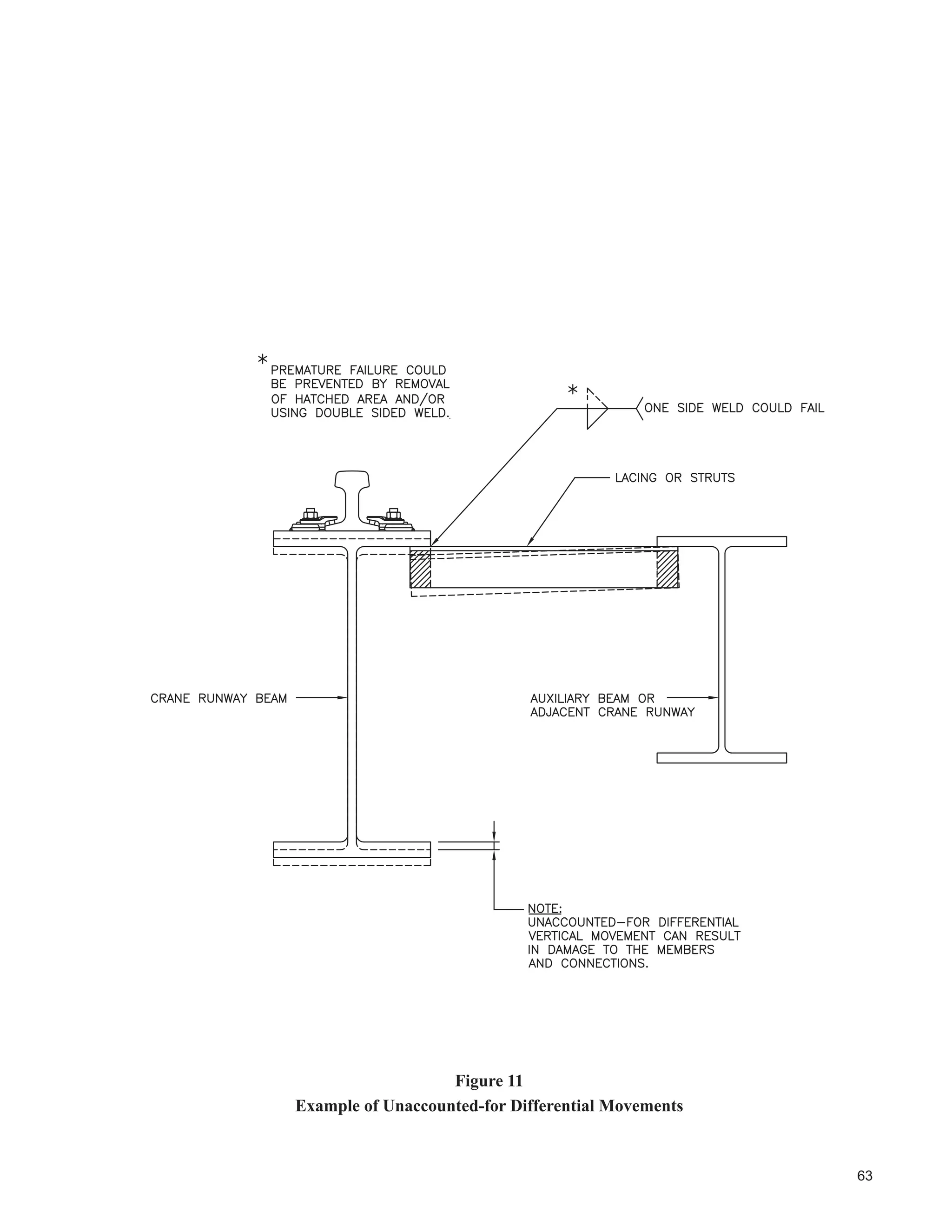
‡ 5XQZD EHDPV DUH XVXDOO FRQWLQXRXV 7KH GHVLJQ VKRXOG DFFRXQW IRU VXFK WKLQJV DV YHUWLFDO ÀH[LELOLW RI
supports and for differential settlement.
‡ Runway beams are subjected to secondary stresses at trolley wheels. Design procedures are given in CMAA
(reference 5).
‡ The building designer must coordinate support locations with the runway beam supplier and the specially
GHVLJQHG RSHQZHE MRLVW VXSSOLHU 7KH GHJUHH RI ÀH[LELOLW RI VXSSRUW ORFDWLRQV VKRXOG EH FRQVLGHUHG
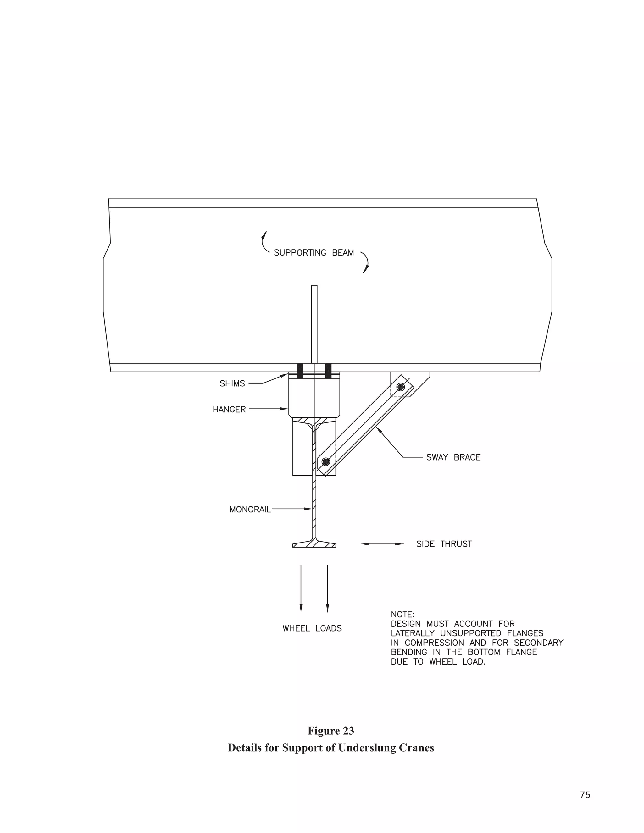
‡ At hanger locations, methods of vertical and lateral adjustment should be incorporated in the hanger design
so that the runway beams can be aligned and so that loads will be distributed evenly and in accordance with
the design assumptions.
‡ Requirements for design for fatigue should be made known to the open-web joist designer by showing
requirements on the structure design drawings.
‡ Anti sway braces should be provided at hanger locations, otherwise premature failure due to fatigue may
occur (see Figure 23).
‡ Longitudinal sway braces should be provided at regular intervals (say 10 m).
‡ Splices in runway beams require special attention to allow a smooth running crane. Typical splices are
shown by Fisher (2004) and Goldman (1990).
‡ 6SHFLDOL]HG DQG KEULG EHDPV VXFK DV :7 RU ::7 WRS ZLWK 67 RU VSHFLDO ERWWRP ÀDQJH DUH XVHG DQG PD
be fabricated from a mix of different steels. Information for design of these beams is provided by CMAA](https://image.slidesharecdn.com/guideforthedesignofcrane-supportingsteelstructures-ramaccrimmon-170302173625/75/Guide-for-the-design-of-crane-supporting-steel-structures-80-2048.jpg)

![41
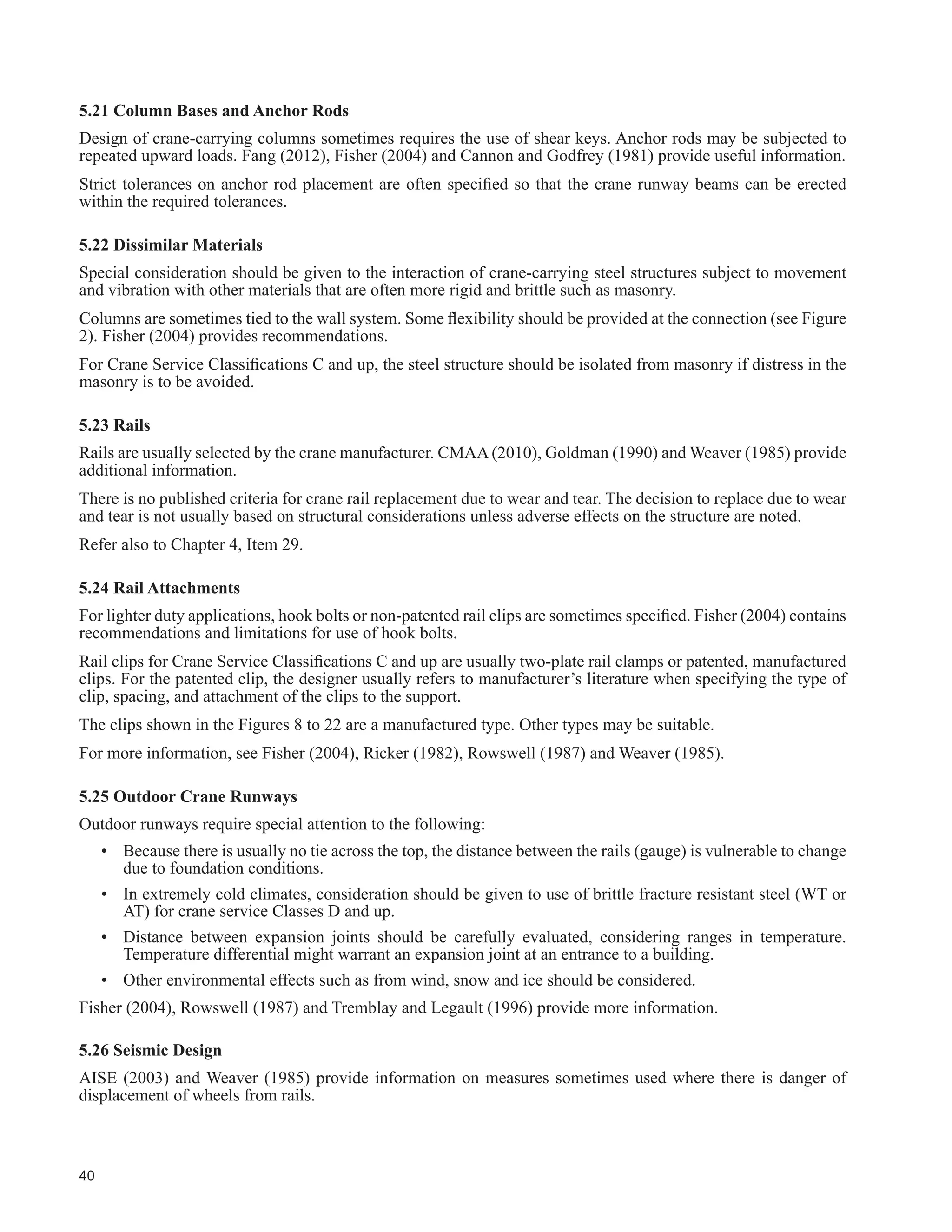
Currentseismicprovisionscontainrecommendationsforanchoringofarchitectural,electricalandmechanicalcomponents
of structures, but do not deal in depth with travelling cranes.
AISE (2003) and MBMA(2006) suggest that the designer consider the dead load of cranes parked for maximum effect.
In case of seismic activity, the mass of the crane will interact with the mass of the supporting structure, acting as a tie
between rails, whether the crane and supporting structure were so designed or not.
Suggestions are:
‡ The designer should check to ensure that the effect of the lateral load due to “E” does not govern over side thrust
on the crane runway beams.
‡ )RU ]RQHV RI KLJKHU VHLVPLF DFWLYLW ZKHUH LW FDQ EH VKRZQ WKDW WKHUH LV D VLJQL¿FDQW ULVN RI GLVSODFHPHQW KROG
down devices should be considered.
‡ In zones where seismic design provisions may be more severe than for wind, the designer should consider use
of a dynamic structural analysis, considering the crane(s) as a tie between rails. The resulting forces on the crane
should be made known to the crane manufacturer.
ThespecialseismicdesignprovisionsoftheNBCC2010andClause27ofS16-09“SeismicDesign”aremostappropriate
for building structures characterized by residential and commercial occupancies. Richard, Koboevic and Tremblay
(2011) note that application of the provisions to many industrial buildings is not straightforward for practicing engineers.
The authors provide useful information and a design example for a typical crane-supporting steel structure.
6WDQGDUGV IRU :HOGLQJ IRU 6WUXFWXUHV 6XEMHFWHG WR )DWLJXH
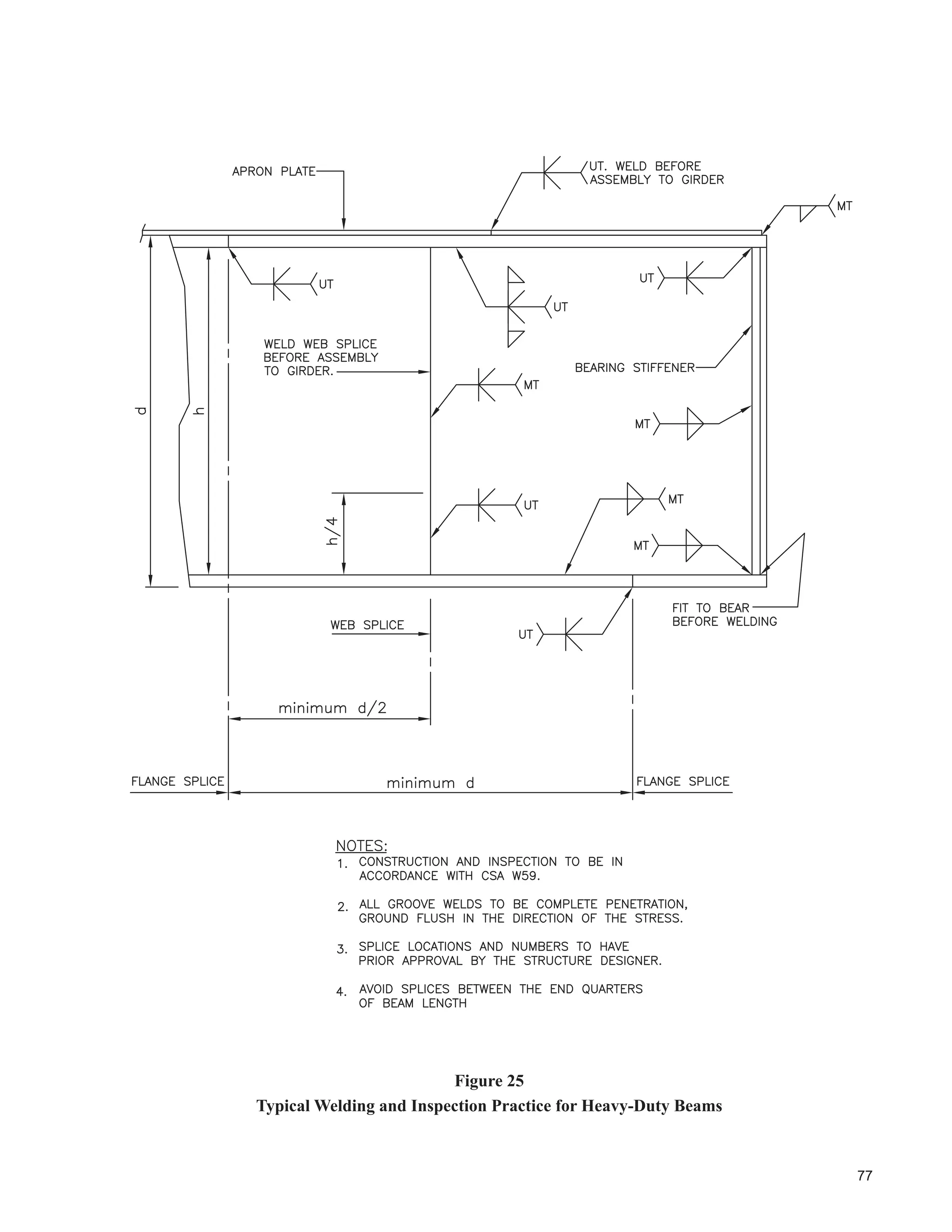
7KH FRQVWUXFWLRQ VSHFL¿FDWLRQ VKRXOG GH¿QH ZKLFK SRUWLRQV RI WKH VWUXFWXUH ZLOO EH VXEMHFW WR WKH PRUH VWULQJHQW
requirements for cyclically loaded structures. See Figure 25 for typical requirements. Usually the critical elements would
be the crane runway beams and their attachments to the supports, but it is the responsibility of the structure designer
to determine if any other components (specially designed open-web joists supporting monorails, for example) need be
included in this category.
Flange plates used in the design of heavy-duty runways should be inspected for the presence of lamellar inclusions in
accordance with the provisions of W59. Material not meeting the standards should be rejected.
See also Chapter 4, Item 26.
5.28 Erection Tolerances
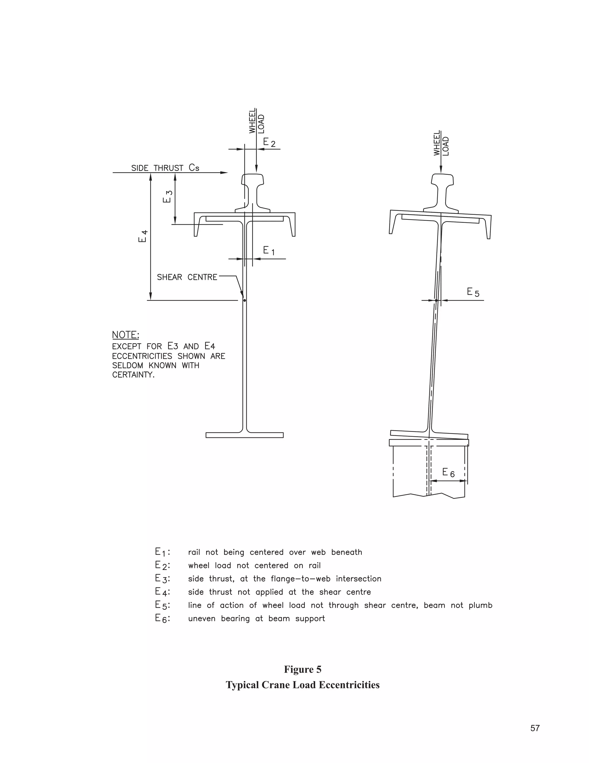
Situations shown in Figure 5 must be minimzed or eliminated.
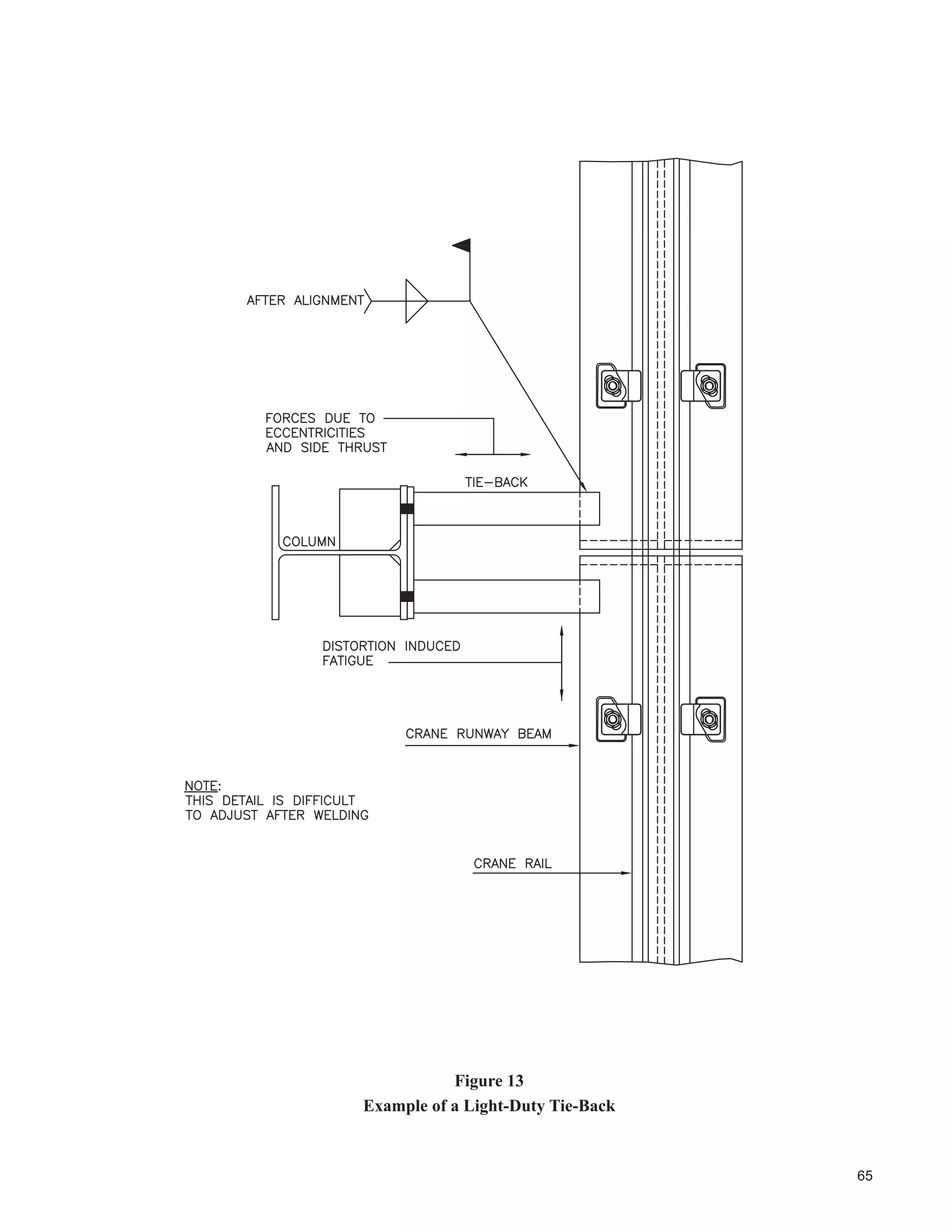
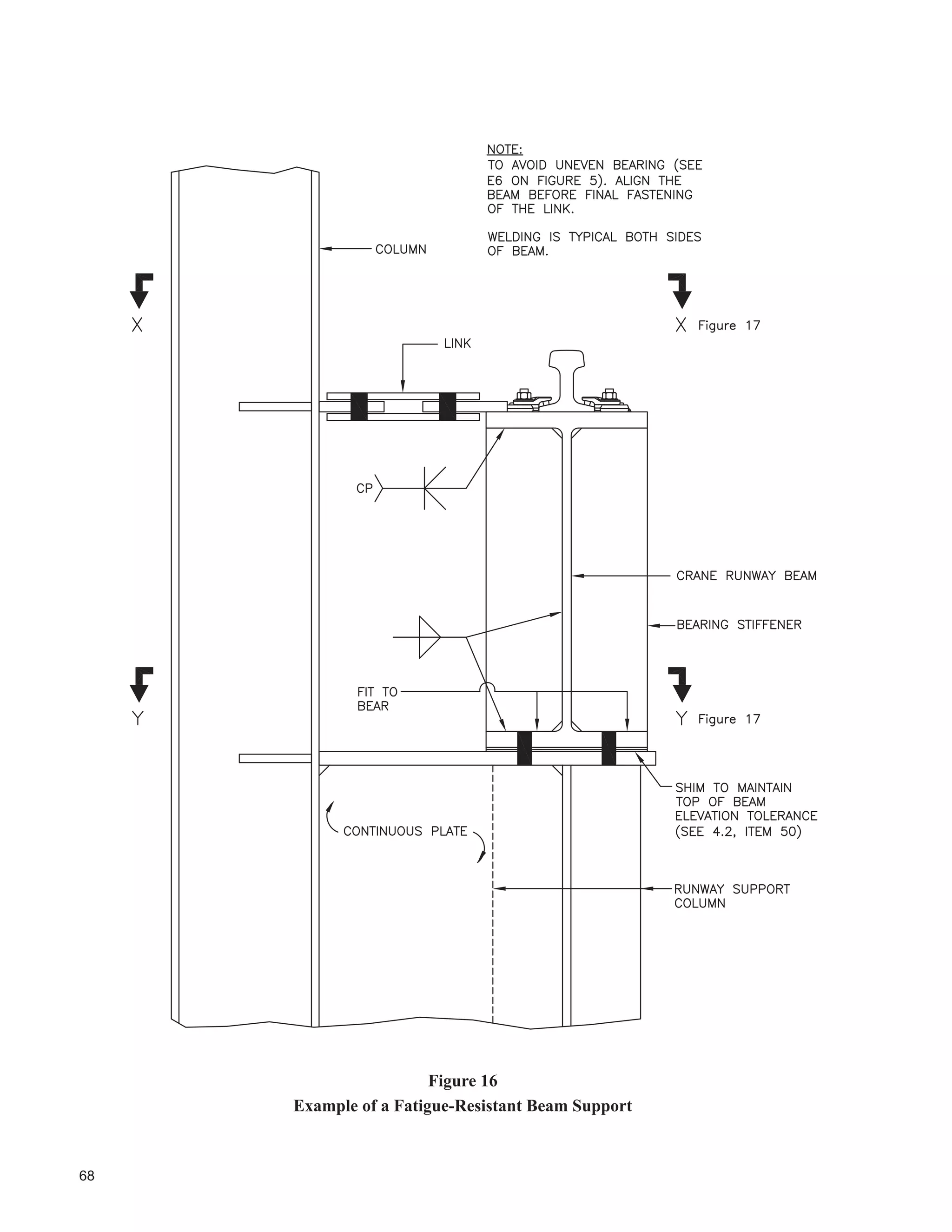
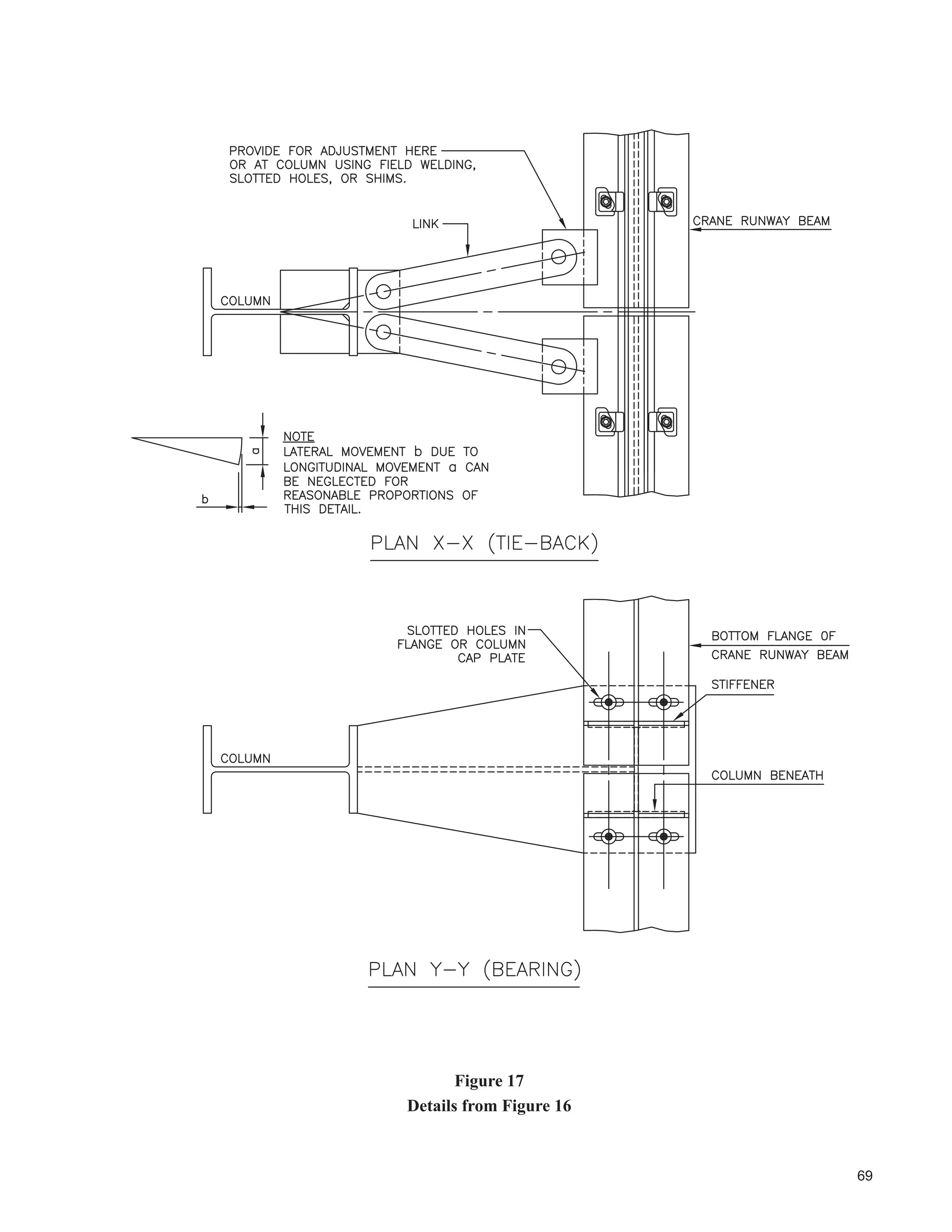
Where possible, bearings and lateral restraints should permit lateral adjustment of the crane runway beams to maintain
alignment with the crane rail. This is often accomplished by use of slotted or oversize holes, and shims. See Figures 13
to 17. Alignment procedures should be reviewed by the designer of the structure. For instance, an incorrect alignment
sequence could result in uneven bearing and eccentricities such as E6 on Figure 5.
Anchor bolt locations should be carefully checked before erection of structural steel. Base plates must be accurately
located so that required tolerances in crane runway beams can be achieved.](https://image.slidesharecdn.com/guideforthedesignofcrane-supportingsteelstructures-ramaccrimmon-170302173625/75/Guide-for-the-design-of-crane-supporting-steel-structures-90-2048.jpg)
![42
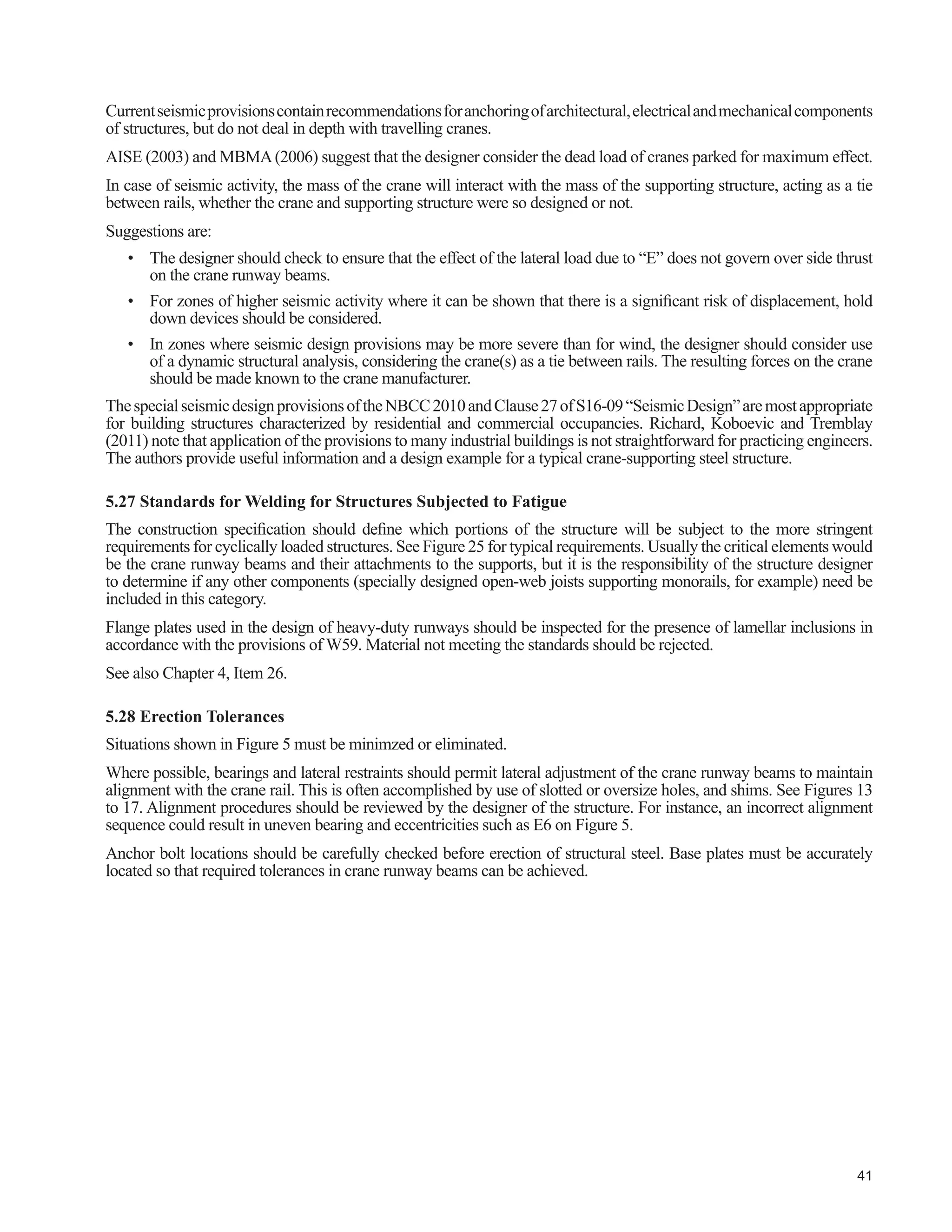
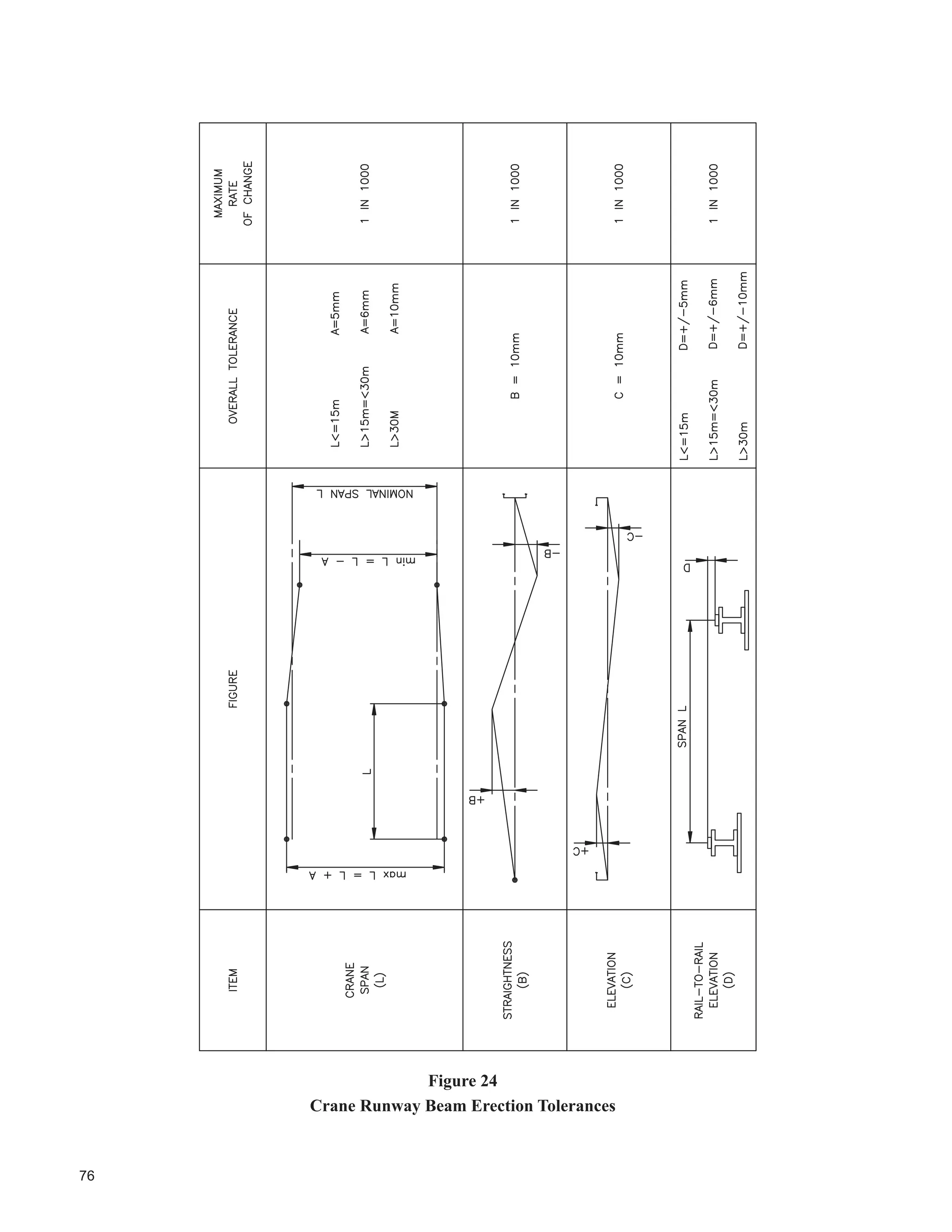
Erection tolerances of crane runway rails should be compatible with minimization of eccentricities on the
supporting structure and within tolerances set by the crane manufacturers. Allowable sweep of crane runway
beams should be consistent with design assumptions for rail eccentricity, rail clip adjustment tolerances and rail
alignment tolerances.
8QOHVV WKH VWUXFWXUH LV VXLWDEO UHVLVWDQW WR FKDQJH LQ JDXJH RI FUDQH UDLOV XQGHU URRI GHDG ORDG ¿QDO DOLJQPHQW RI
the crane runway beams should be deferred until the full dead load of the roof is in place.
Figure 24 shows the requirements of the CMAA. It is based on requirements for satisfactory crane performance.
Other tolerances such as those shown in table 4.1 are related to fabrication and erection tolerances. Both criteria
VKRXOG DSSO 7KH IDEULFDWLRQ VSHFL¿FDWLRQ VKRXOG DFFRXQW IRU UHTXLUHG WROHUDQFHV ZKLFK PD EH PRUH VHYHUH WKDQ
the individual standards permit.
,Q FDVH RI FRQÀLFW ZLWK ODXVH RI 6 DQG UHFRPPHQGDWLRQV FRQWDLQHG HOVHZKHUH LQ WKLV GHVLJQ JXLGH
the more stringent requirements should govern.
KHFNLQJ RI HUHFWLRQ WROHUDQFHV VKRXOG EH E LQGHSHQGHQW VXUYH :KHUH WKH VSHFL¿HG WROHUDQFHV DUH H[FHHGHG
WKH GHVLJQHU VKRXOG EH QRWL¿HG $IWHU DVVHVVPHQW WKH GHVLJQHU VKRXOG VSHFLI UHPHGLDO PHDVXUHV DV PD EH UH-
quired.
6WDQGDUGV IRU ,QVSHFWLRQ
Refer also to Sections 5.27 and 5.28.
Figure 25 shows commonly used standards for welding and inspection of crane runway beams.
See W59 for more information.
5HIHUULQJ WR 6$ 6WDQGDUG : :HOGLQJ LQVSHFWLRQ RUJDQL]DWLRQV DQG LQGLYLGXDO LQVSHFWRUV PXVW EH FHUWL¿HG
to CSA Standards W178 and W178.2 respectively. For inspection of other aspects of fabrication and erection,
QR VWDQGDUG IRU FHUWL¿FDWLRQ H[LVWV ,QVSHFWRUV VKRXOG EH FRPSOHWHO IDPLOLDU ZLWK WKH UHTXLUHPHQWV RI WKH GHVLJQ
GUDZLQJV DQG SURMHFW VSHFL¿FDWLRQV LQFOXGLQJ DOO VSHFL¿HG VWDQGDUGV DQG FRGHV LQFOXGLQJ UHTXLUHPHQWV IRU
dynamically loaded structures as may be applicable.
6$6WDQGDUG % VSHFL¿HV WKH PLQLPXP UHTXLUHPHQWV IRU LQVSHFWLRQ WHVWLQJ DQG PDLQWHQDQFH RI FUDQHV DQG
LQFOXGHV VXSSRUWLQJ VWUXFWXUHV 6HFWLRQ VSHFL¿HV WKDW D 3URIHVVLRQDO (QJLQHHU PXVW FHUWLI WKH VXSSRUWLQJ
structure. The user is advised to consult with the jurisdiction having authority regarding adoption of this Standard,
and whether there may be exemptions or additions.
5.30 Maintenance and Repair
Crane-carrying structures subjected to fatigue, in combination with:
‡ age,
‡ unintended use (often called abuse),
‡ inadequate design,
‡ imperfections in materials,
‡ substandard fabrication,
‡ substandard erection methods, and
‡ building component movements, such as foundations,
require maintenance and repair. Repair procedures should incorporate the recommendations of an experienced
structure designer, or the repair can create effects that are more serious that the original imperfection.
Referring also to item 5.29, it is recommended that periodic inspection and maintenance be done and a checklist
should be prepared for the maintenance personnel.
Fisher (2004), Millman (1991, 1996) and Reemsnyder and Demo (1978) provide additional information.](https://image.slidesharecdn.com/guideforthedesignofcrane-supportingsteelstructures-ramaccrimmon-170302173625/75/Guide-for-the-design-of-crane-supporting-steel-structures-91-2048.jpg)
![50
REFERENCES
1. AISE. 2003. Guide for the Design and Construction of Mill Buildings. Association of Iron and Steel
Engineers.Technical Report No. 13, Pittsburgh, Pennsylvania.
2. ASCE. 2002. Minimum Design Loads for Buildings and Other Structures. American Society of Civil
Engineers. Standard SEI/ASCE 7-02, New York.
3. Cannon, R.W., Godfrey, D.A. and Moreadith F.L. 1981. Guide to the Design of Anchor Bolts and Other
Steel Embedments. Concrete International, Vol. 3, No. 7, July. Farmington, Illinois.
0$$ 6SHFL¿FDWLRQV IRU 7RS 5XQQLQJ %ULGJH DQG *DQWU 7SH 0XOWLSOH *LUGHU (OHFWULF 2YHUKHDG
7UDYHOOLQJ UDQHV UDQH 0DQXIDFWXUHUV$VVRFLDWLRQ RI$PHULFD DQ$I¿OLDWH RI 0DWHULDO +DQGOLQJ ,QGXVWU
6SHFL¿FDWLRQ 5HYLVHG KDUORWWH 1RUWK DUROLQD
0$$ 6SHFL¿FDWLRQV IRU 7RS 5XQQLQJ DQG 8QGHU 5XQQLQJ 6LQJOH *LUGHU (OHFWULF 7UDYHOOLQJ
UDQHV 8WLOL]LQJ 8QGHU 5XQQLQJ 7UROOH +RLVW UDQH 0DQXIDFWXUHUV $VVRFLDWLRQ RI $PHULFD DQ $I¿OLDWH
RI 0DWHULDO +DQGOLQJ ,QGXVWU 6SHFL¿FDWLRQ 5HYLVHG KDUORWWH 1RUWK DUROLQD
6. CSA.1996.SafetyStandardforMaintenanceandInspectionofOverheadCranes,GantryCranes,Monorails,
Hoists, and Trolleys. Canadian Standards Association Standard B167-96, Etobicoke, Canada.
7. Demo, D.A. and Fisher, J.W. 1976. Analysis of Fatigue of Welded Crane Runway Girders. American
Society of Civil Engineers. Journal of the Structural Division, May. Chicago, Illinois.
8. Ellifritt, D.S., and Lue, D.-M. 1998. Design of Crane Runway Beam with Channel Cap. American Institute
of Steel Construction. Engineering Journal, Second Quarter. Chicago, Illinois
9. Fang, S.-F. 2012. Applications of Pretensioned Anchor Rods in Industrial Facilities. American Institute of
Steel Construction. Engineering Journal, First Quarter. Chicago. Illinois.
10. Fisher, J.M. 2004. Industrial Buildings, Roofs to Column Anchorage. Second Edition. American Institute
of Steel Construction, Inc. Steel Design Guide Series 7. Chicago, Illinois.
11. Fisher, J.W., Kulak, G.L. and Smith, I.F.C. 1997. A Fatigue Primer for Structural Engineers. Advanced
Technology for Large Structural SystemsATLSS Report No. 97-11. Lehigh University, October. Bethlehem,
Pennsylvania.
12. Fisher, J.M., and Thomas, S.J. 2002. Design Concepts for Jib Cranes. American Institute of Steel
Construction. Engineering Journal, Second Quarter. Chicago, Illinois.
13. Fisher, J.M., and Van de Pas, J.P. 2002. New Fatigue Provisions for the Design of Crane Runway Girders.
American Institute of Steel Construction. Engineering Journal, Second Quarter. Chicago, Illinois.
14. Ziemian, R.D. 2010. Guide to Stability Design Criteria for Metal Structures, Sixth Edition. John Wiley and
Sons, Inc., Hoboken, New Jersey.
15. Goldman, C. 1990. Design of Crane Runway Girders for Top Running and Under Running Cranes and
Monorails. Canadian Journal of Civil Engineering, Volume 17. Montreal, Quebec.
16. Griggs, P.H., and Innis, R.H. 1978. Support Your Overhead Crane. Association of Iron and Steel Engineers.
Proceedings of the 1978 Annual Convention, Chicago, September 25 -27. Pittsburgh, Pennsylvania.
17. Griggs, P.H. 1976. Mill Building Structures. Proceedings of the Canadian Structural Engineering
Conference, 1976. Toronto, Ontario.
18. Johnson, P.C. and Laman, J.A. 2010. Singly Symmetric Combination Section Crane Girder Design Aids.
American Institute of Steel Construction. Engineering Journal. Fourth Quarter. Chicago, Illinois.
19. Kulak, G.L. and Grondin, G.Y. 2010. Limit States Design in Structural Steel, Ninth Edition. Canadian
Institute of Steel Construction, Markham, Ontario.
20. Kulak, G.L., Fisher, J.W., and Struik, J.A. 1987 Guide to Design Criteria for Bolted and Riveted Joints,
Second Edition. John Wiley and Sons, Inc., New York, New York.
21. Laman,J.A.1996.LRFDCraneGirderDesignProcedureandAids.AmericanInstituteofSteelConstruction.
Engineering Journal, Fourth Quarter. Chicago, Illinois.](https://image.slidesharecdn.com/guideforthedesignofcrane-supportingsteelstructures-ramaccrimmon-170302173625/75/Guide-for-the-design-of-crane-supporting-steel-structures-100-2048.jpg)
![55
)LJXUH
7SLFDO +RUL]RQWDO 5RRI %UDFLQJ DW /RZHU KRUGV RI 5RRI 7UXVVHV](https://image.slidesharecdn.com/guideforthedesignofcrane-supportingsteelstructures-ramaccrimmon-170302173625/75/Guide-for-the-design-of-crane-supporting-steel-structures-105-2048.jpg)

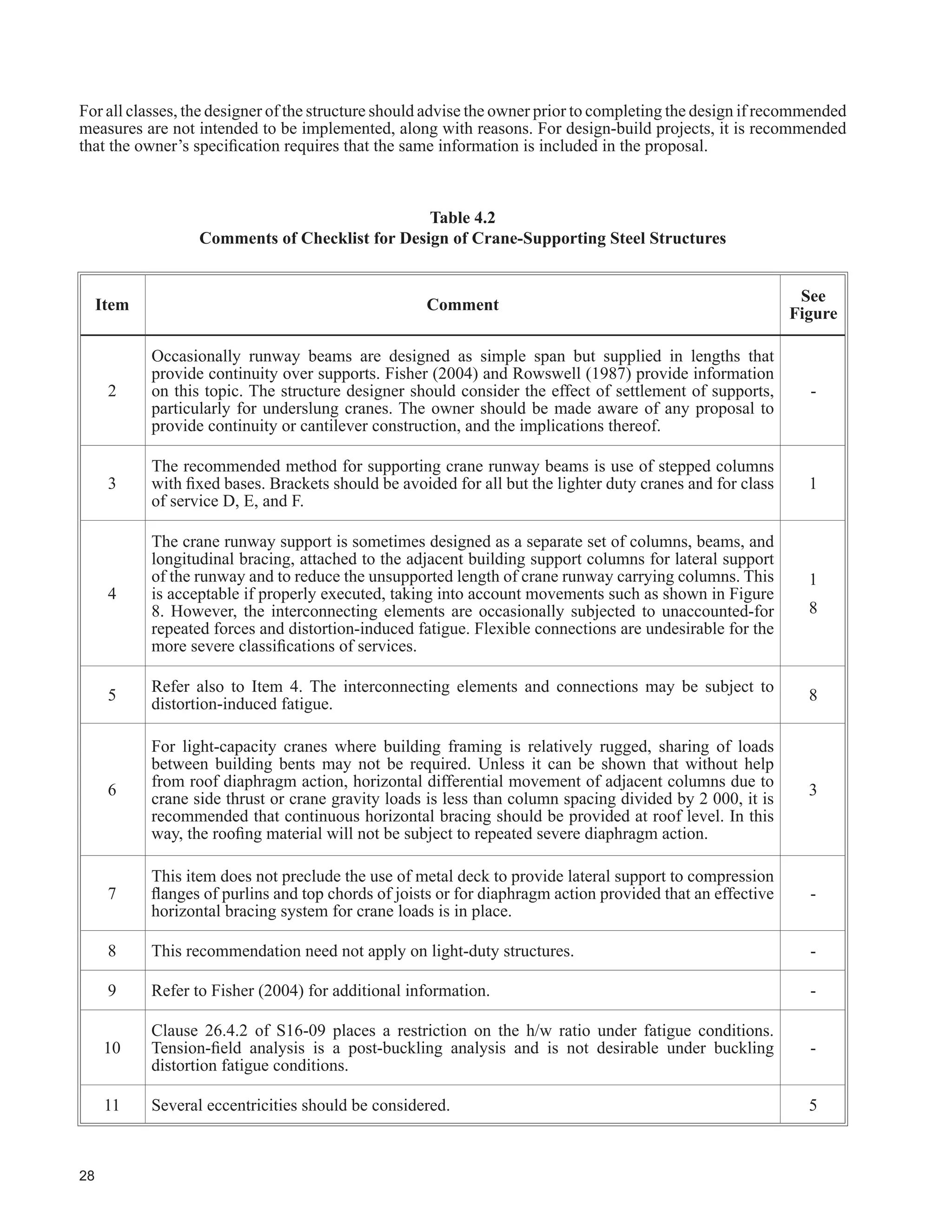
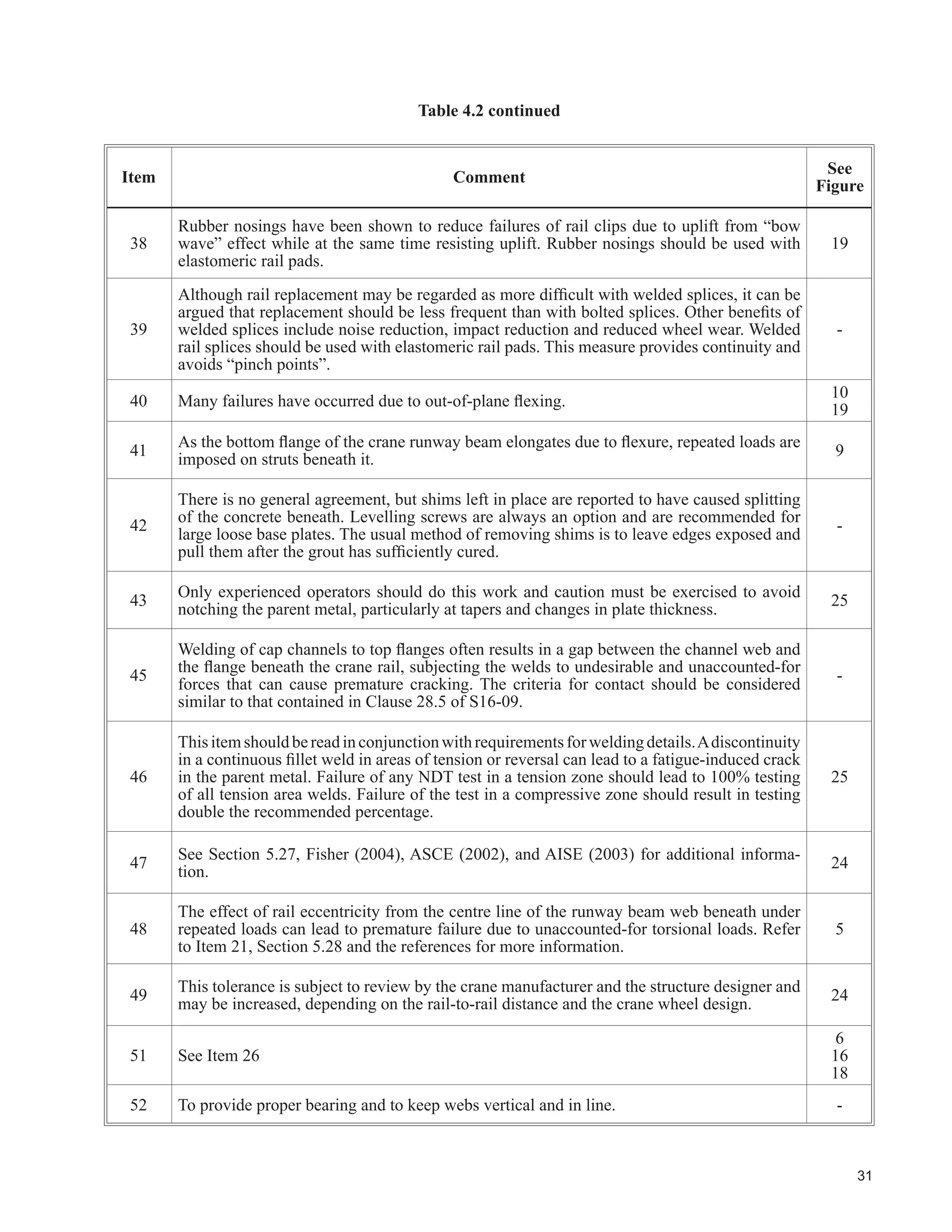
This document provides guidelines for the design of crane-supporting steel structures. It covers loads specific to these structures, design for repeated loads and fatigue, classification of structures, design and construction measures, and topics related to rehabilitation and upgrading of existing structures. The document contains several chapters that describe loads, fatigue design procedures, classification of crane service, examples of duty cycle analyses, design and construction checklists, and other topics such as clearances, attachments, and welding standards.
Overview and purpose of the design guide for crane-supporting steel structures in accordance with Canadian codes.
The guide contains detailed chapters on design, construction measures, rehabilitation, and upgrading of existing structures.
Foreword introducing the CISC, its mission, and its role in providing technical information for crane-supporting structures.
The guide aims to provide practical guidelines and incorporate changes in building codes and best practices for crane structure design.
Introduction to crane loads, including their importance and considerations for the design of crane-supporting structures.
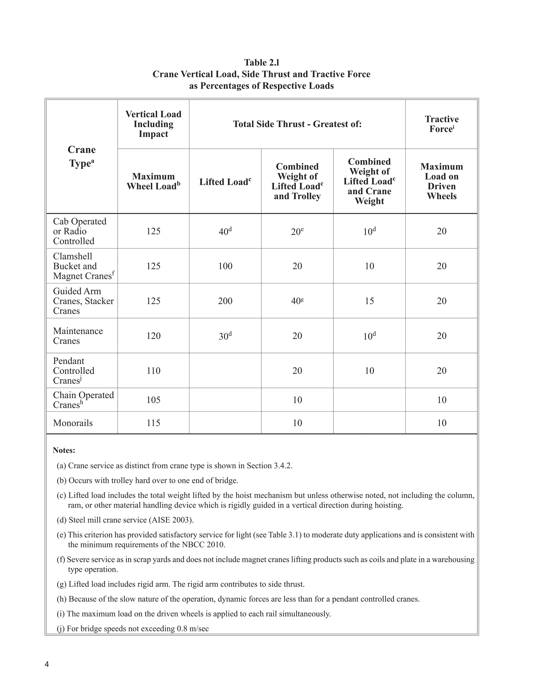
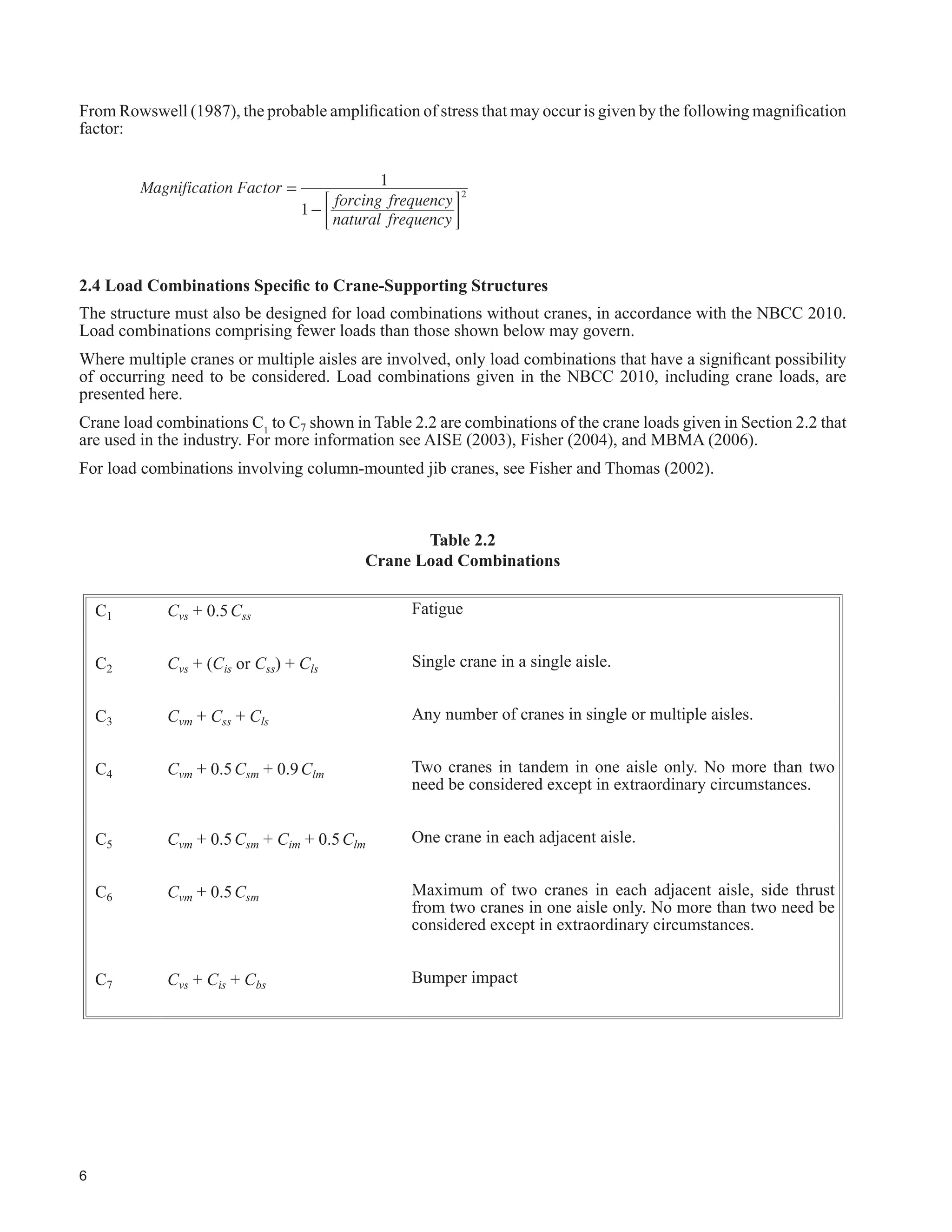
Detailed information on vertical loads, side thrust, traction loads, bumper impacts, vibrations, and load combinations for cranes.Methods for designing crane-supporting structures to withstand repeated loads, focusing on fatigue damage and life expectancy.
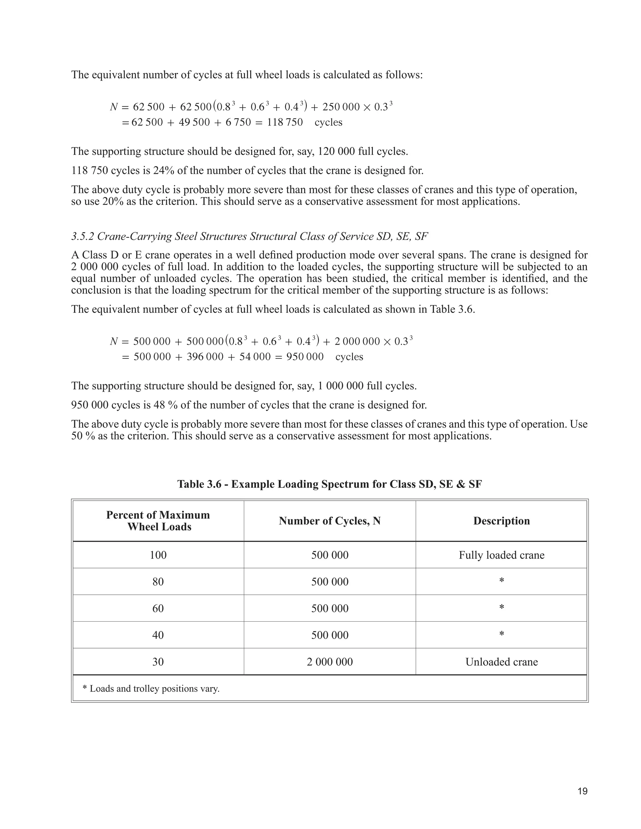
Design criteria for various classes of crane services, outlining load cycles, examples, and considerations for design.
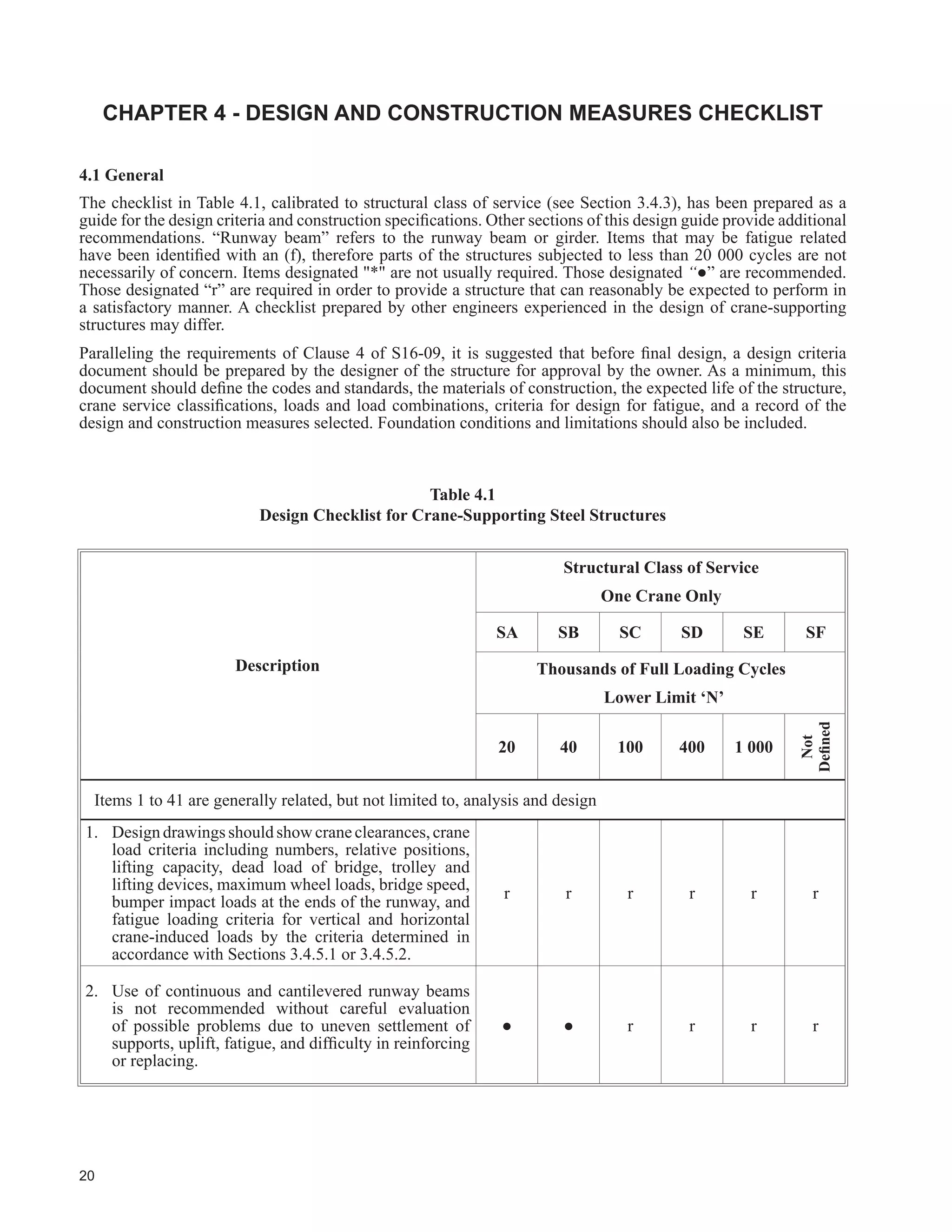
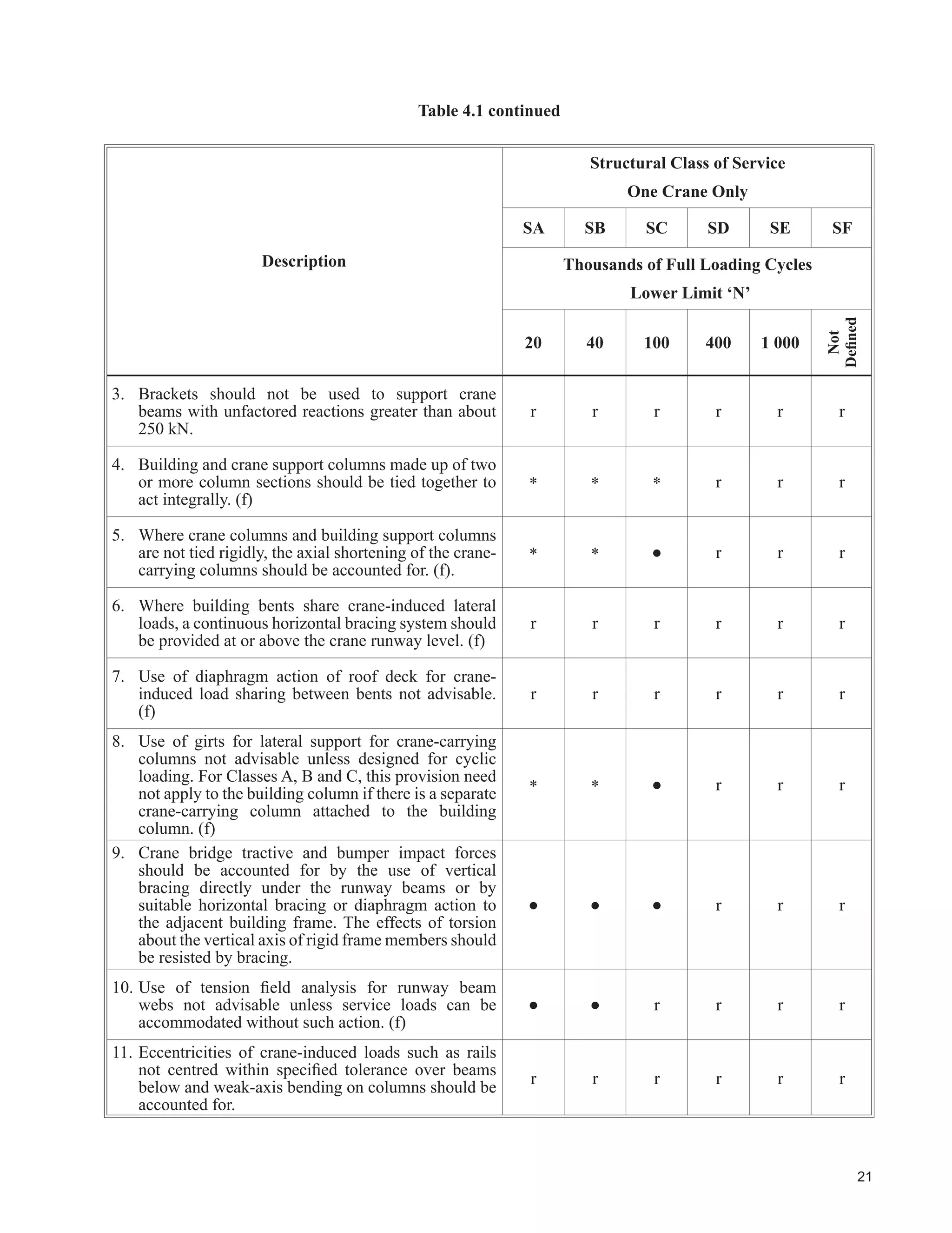
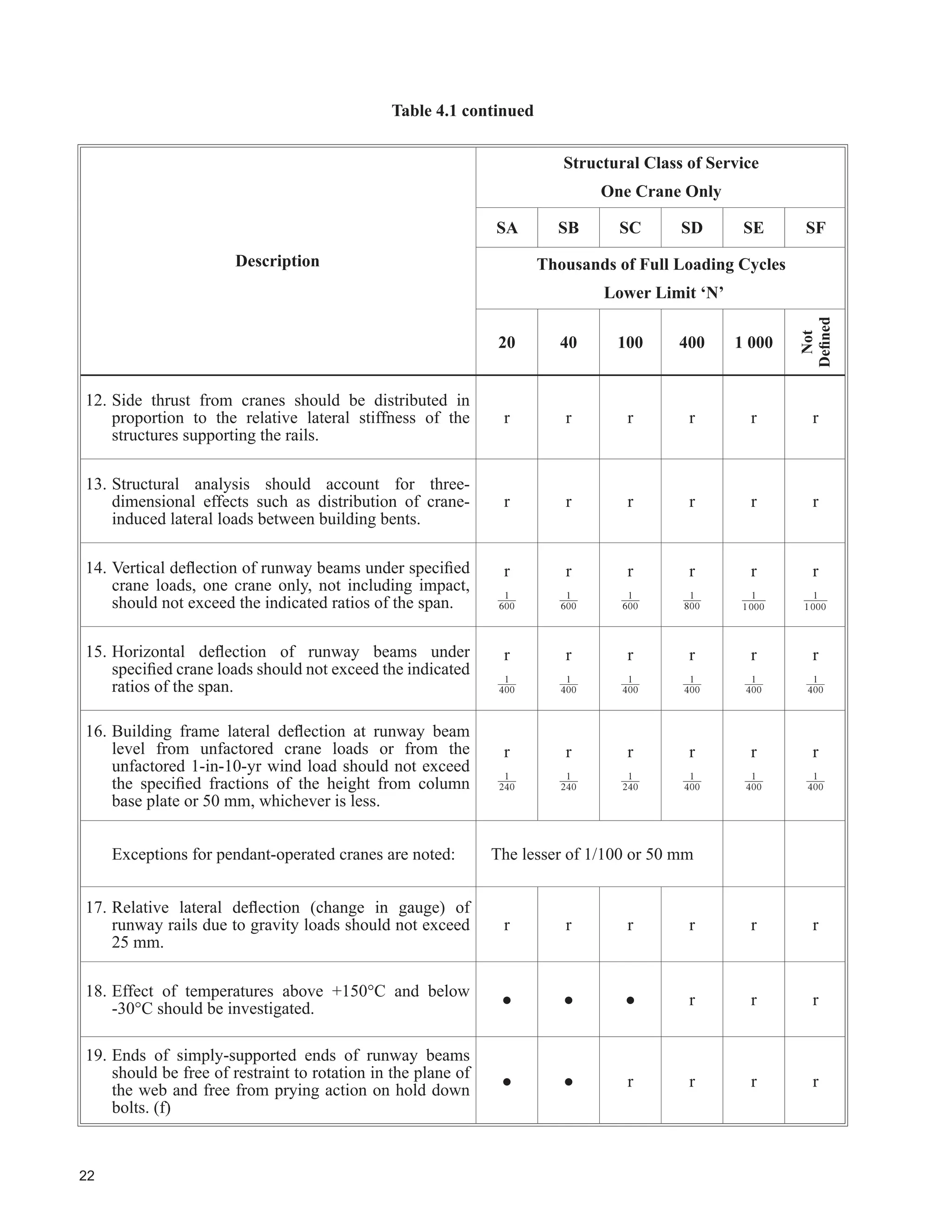
A checklist for designing crane-supporting structures, focusing on fatigue-related issues and construction details.
Miscellaneous considerations, including clearances, methods of analysis, and the interaction between cranes and structures.
Addressing the assessment and upgrade of existing steel structures to meet current design standards and practices.
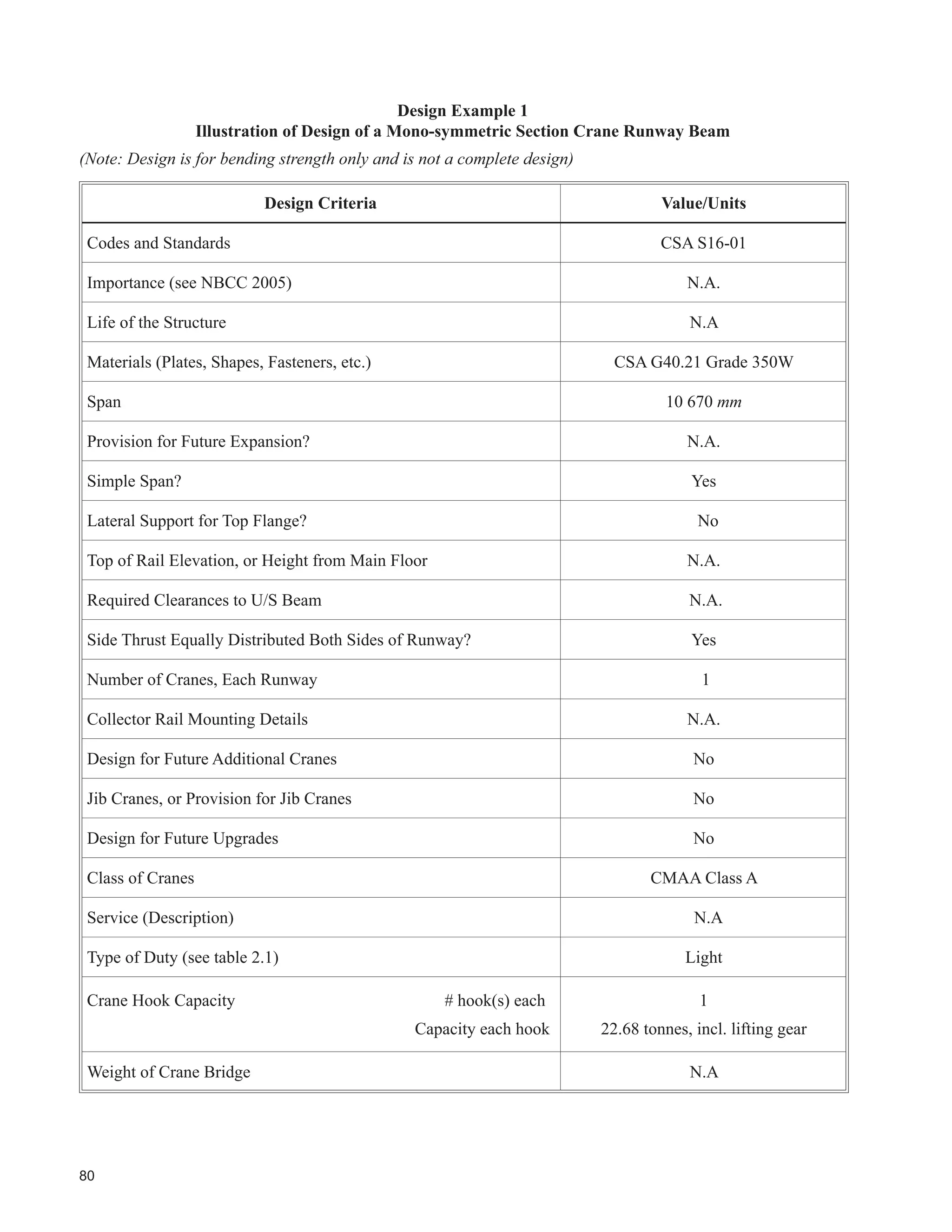
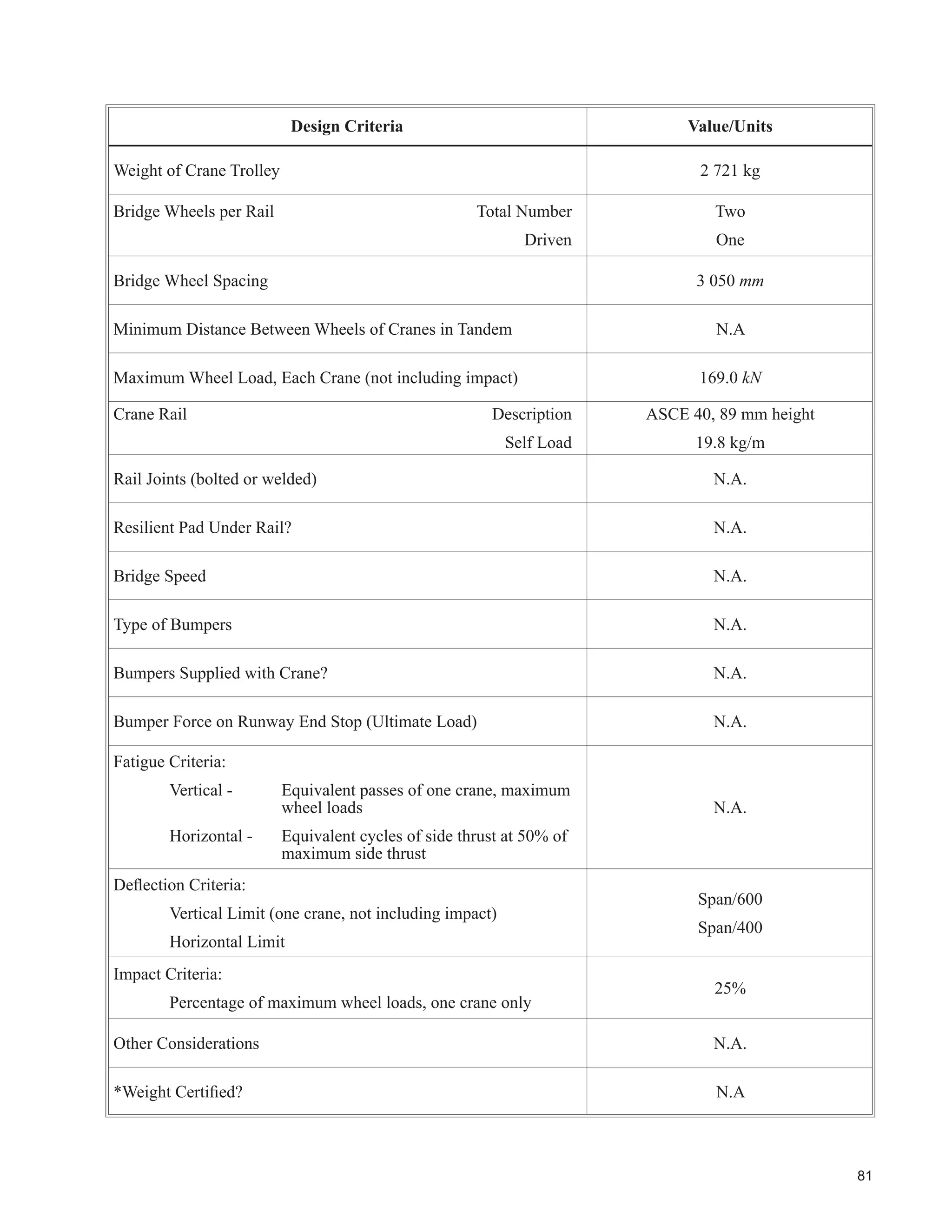
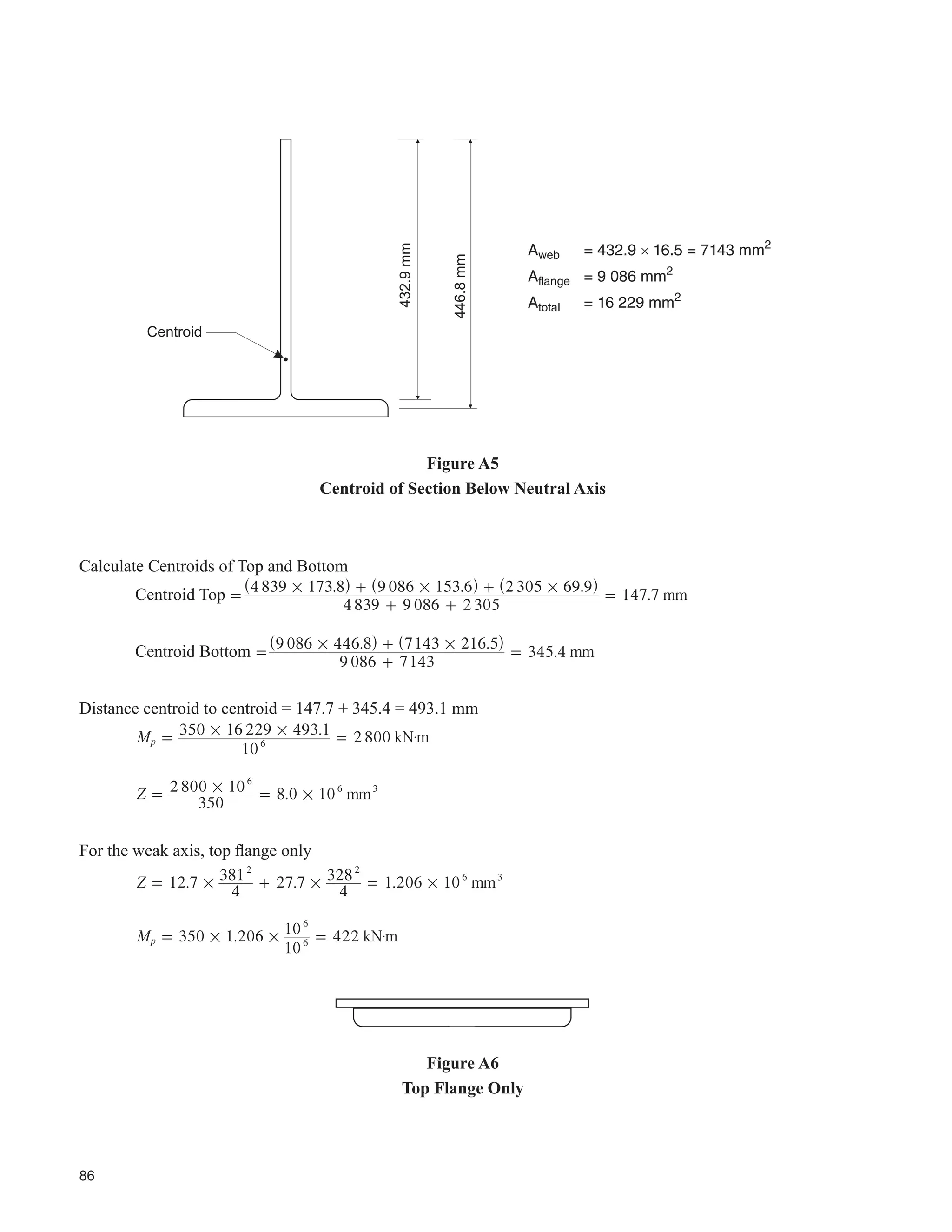
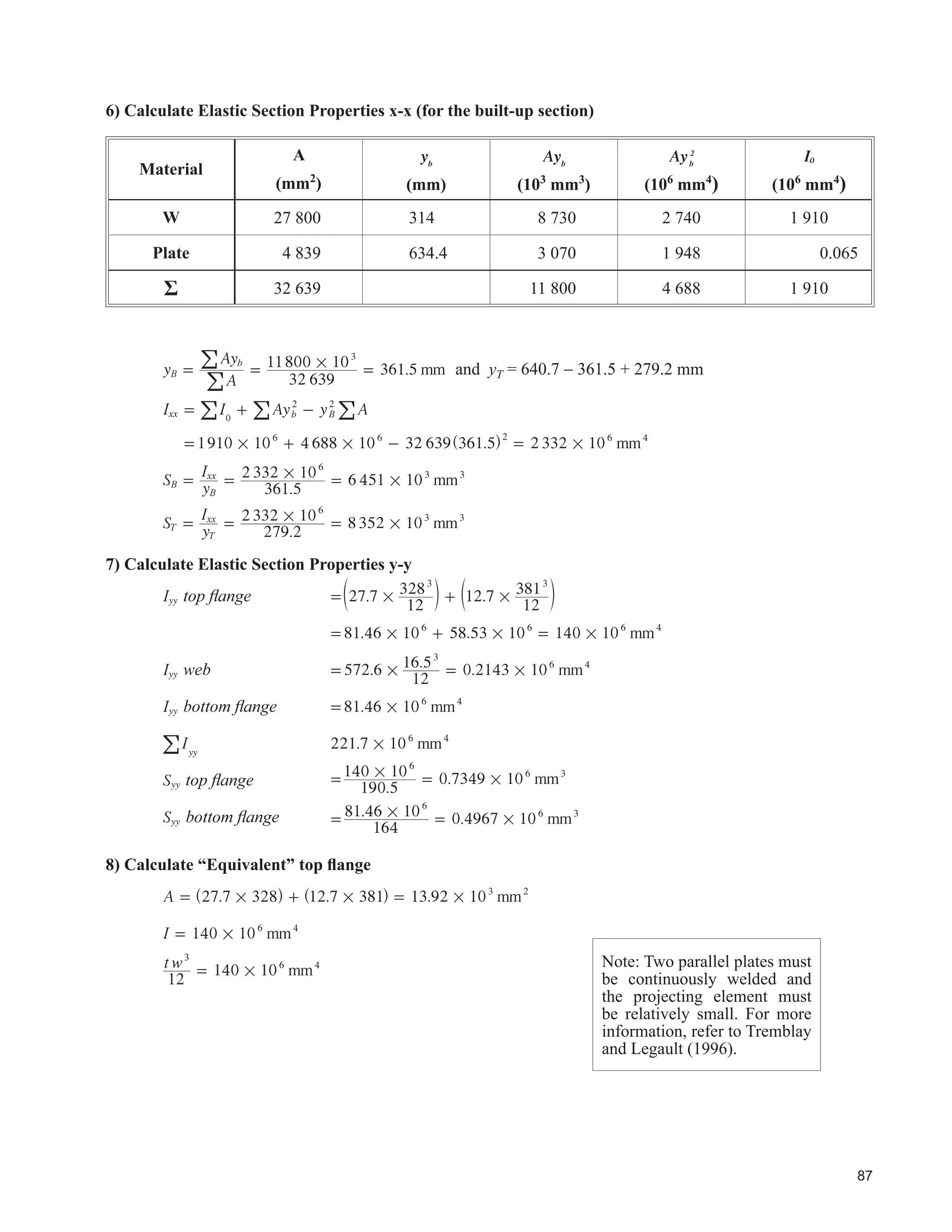
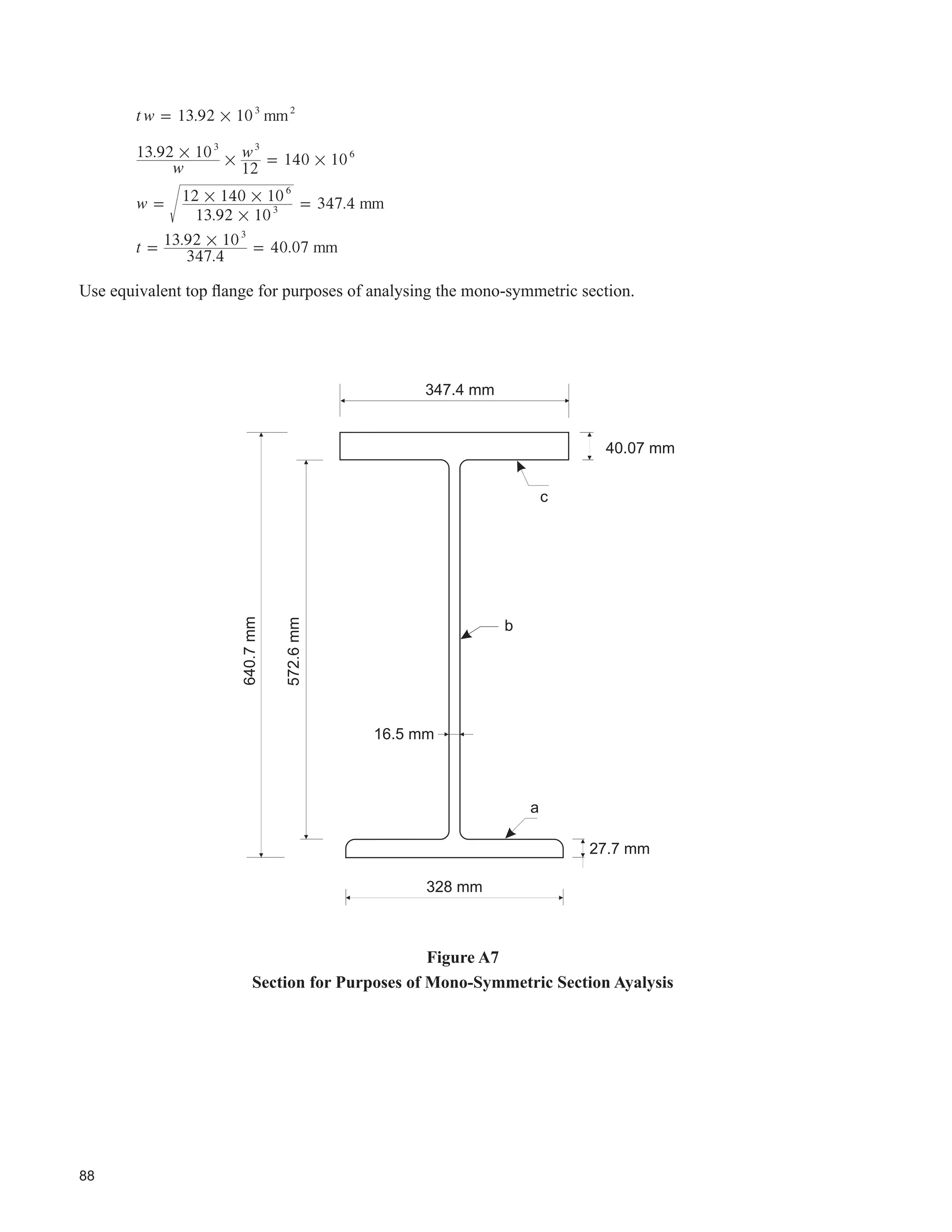
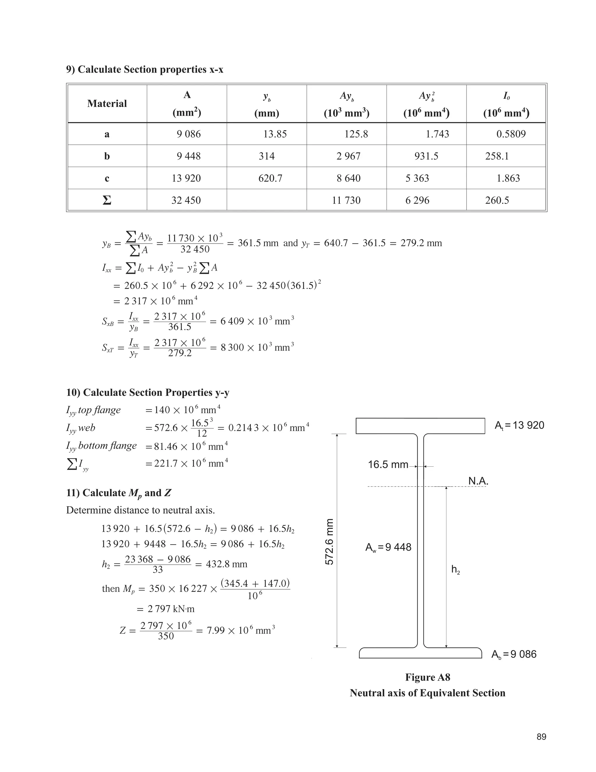
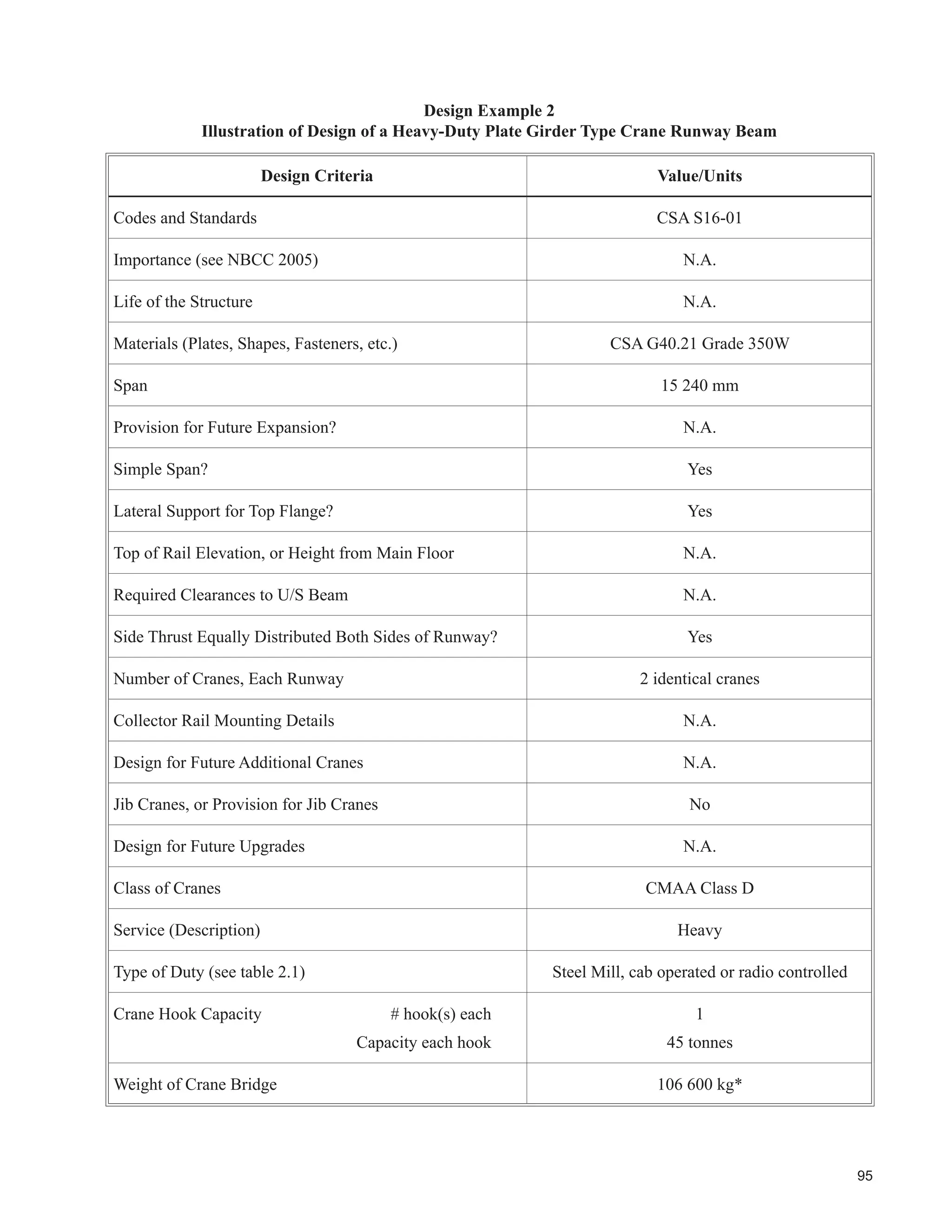
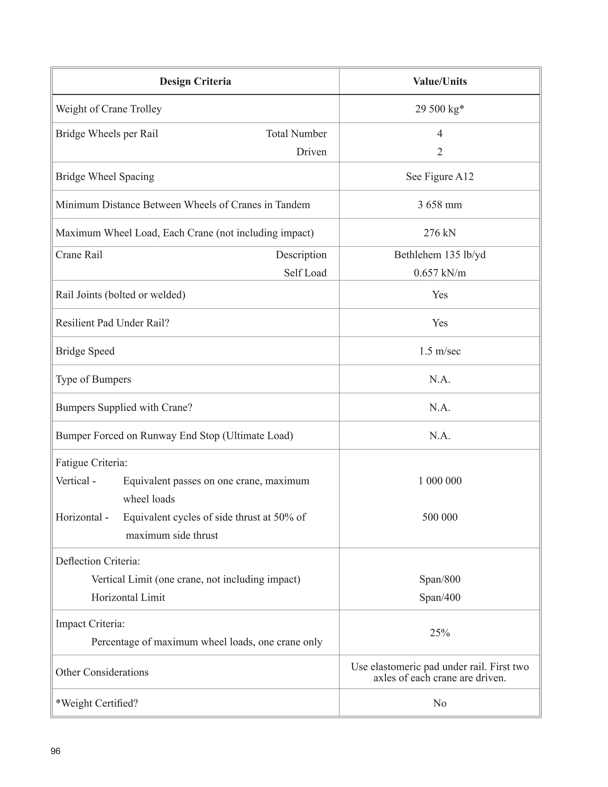
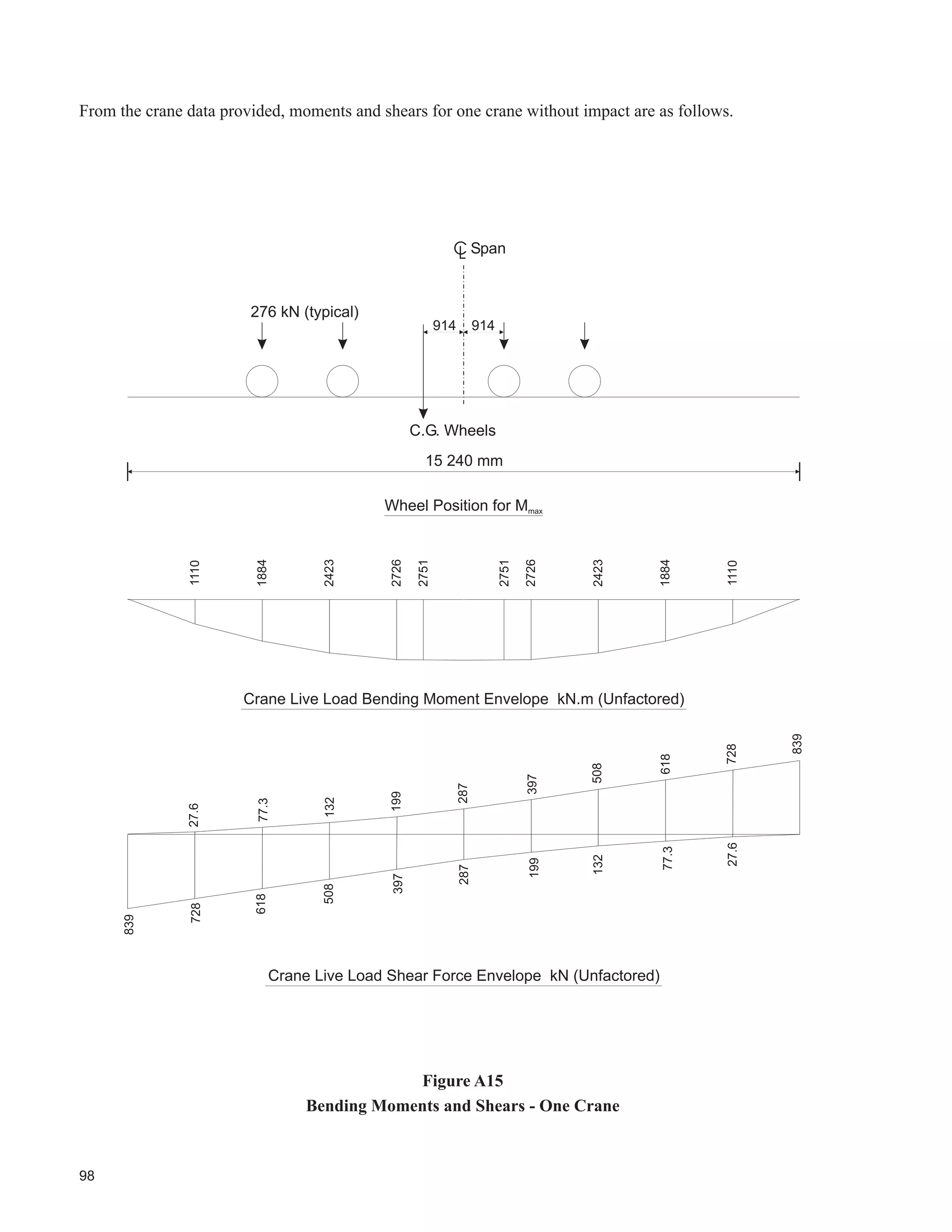
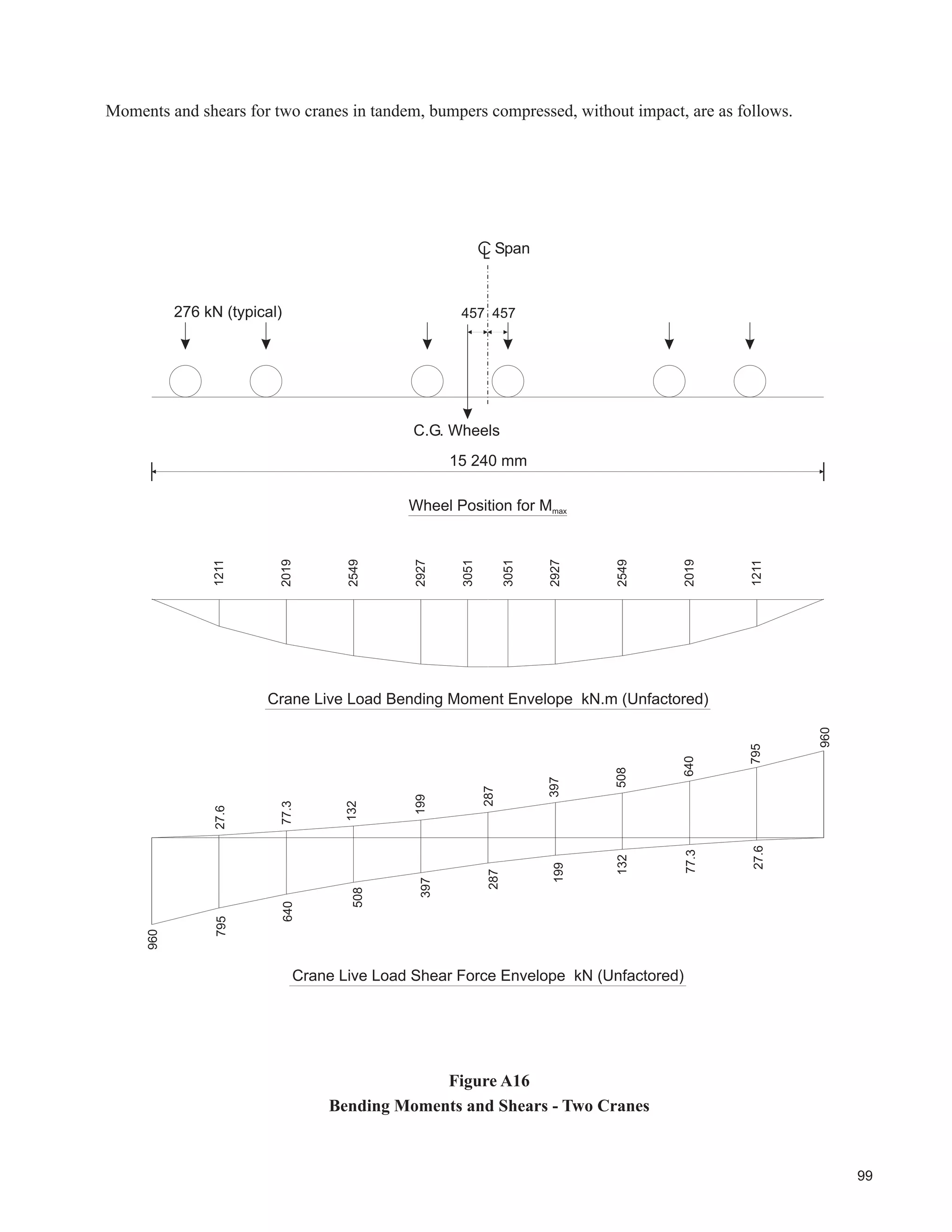
Detailed practical examples illustrating the design process for crane runway beams, including structural calculations.
Wrap-up of the design considerations presented in the guide along with comprehensive references for further information.
Practical examples demonstrating detailed design processes and considerations for crane-supporting structures.
Summary of key points, design criteria, and recommendations for ensuring the safety and efficiency of crane-supporting structures.
An index of key terms and topics related to crane-supporting steel structures, facilitating navigation of the document.


