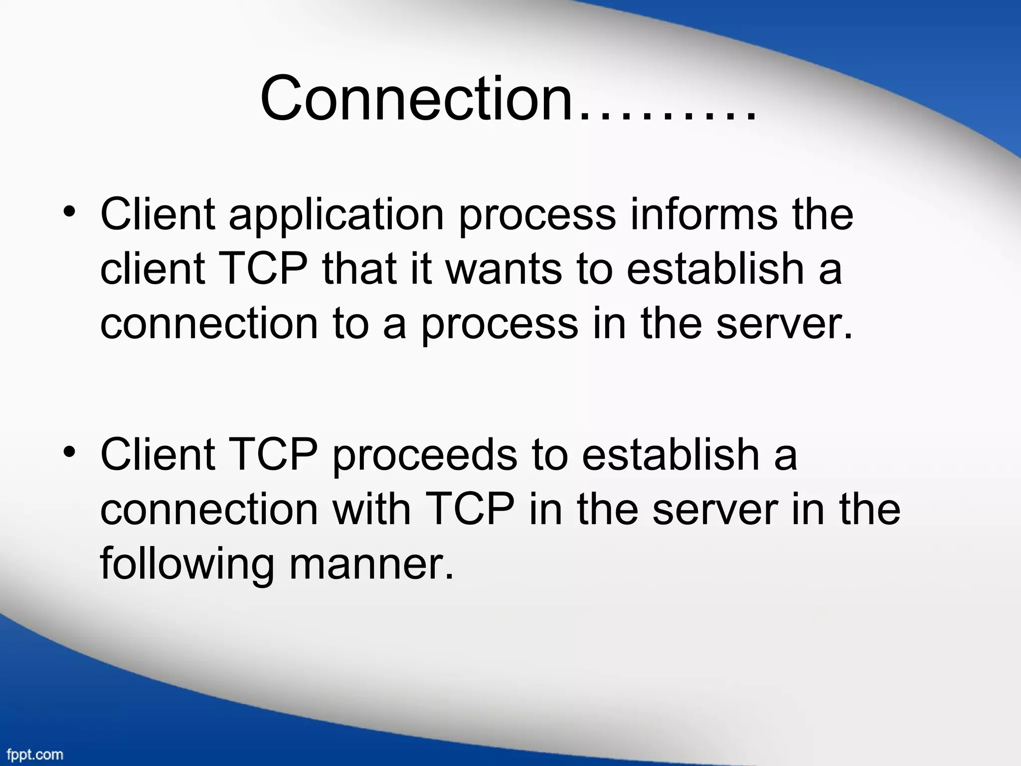
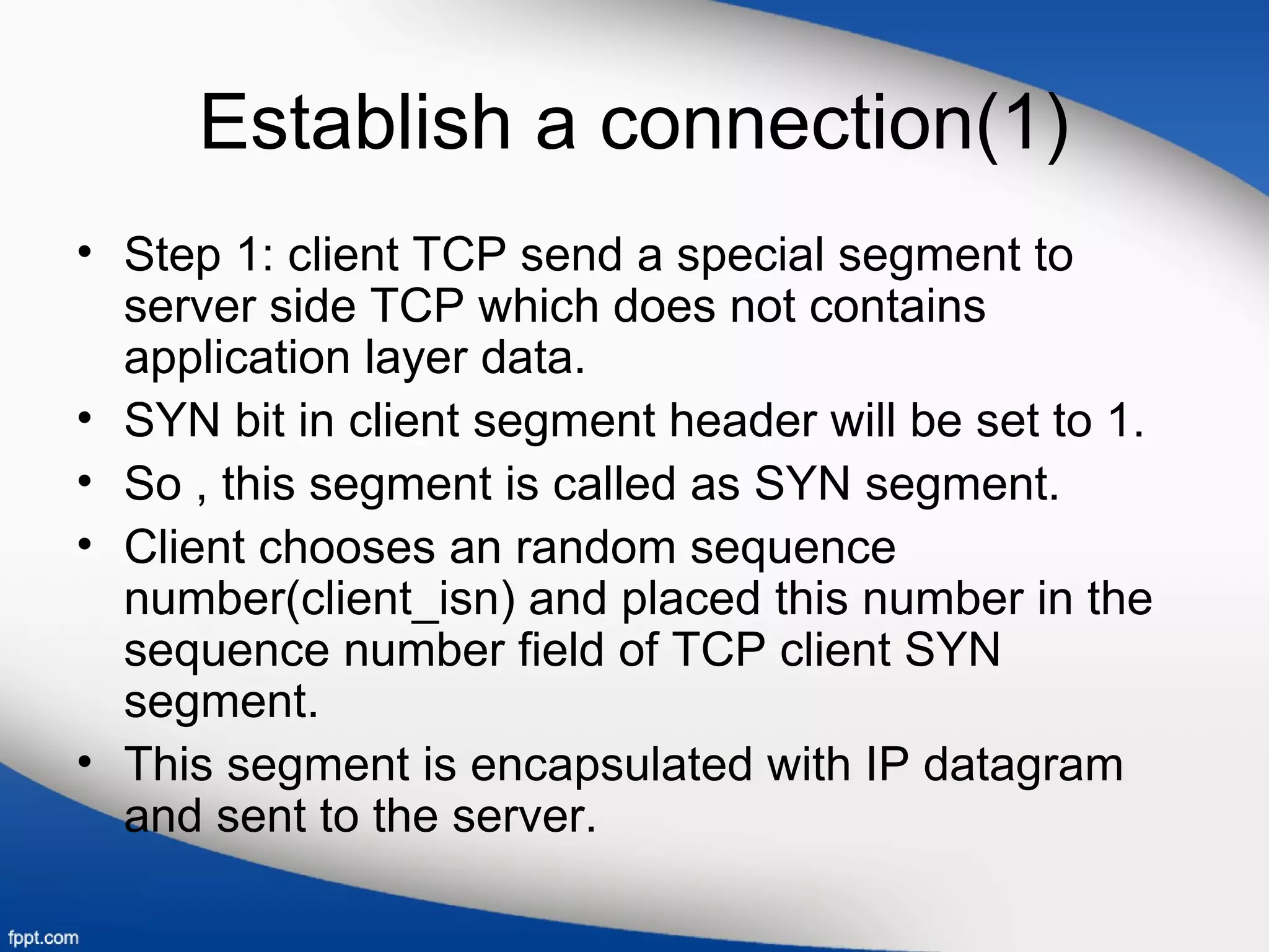
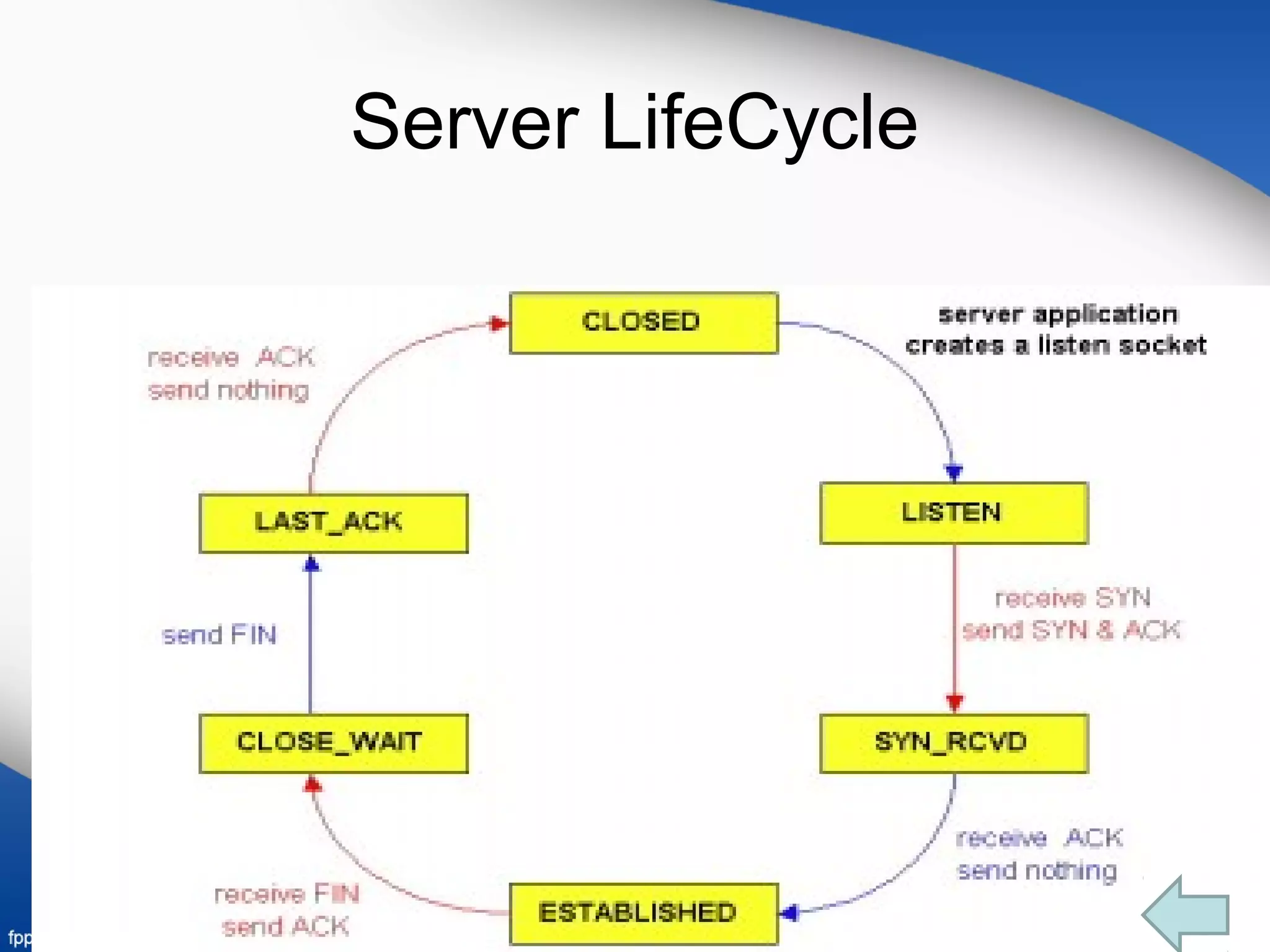
TCP provides flow control through the use of a receive window to prevent a sender from overflowing the receiver's buffer. The receive window tells the sender how much free buffer space is available at the receiver. TCP estimates the round-trip time (RTT) between hosts by taking an exponential weighted moving average of sample RTT measurements for segments that are successfully transmitted and acknowledged. Connections between clients and servers are established through a three-way handshake and closed through an orderly shutdown that releases resources on both ends.


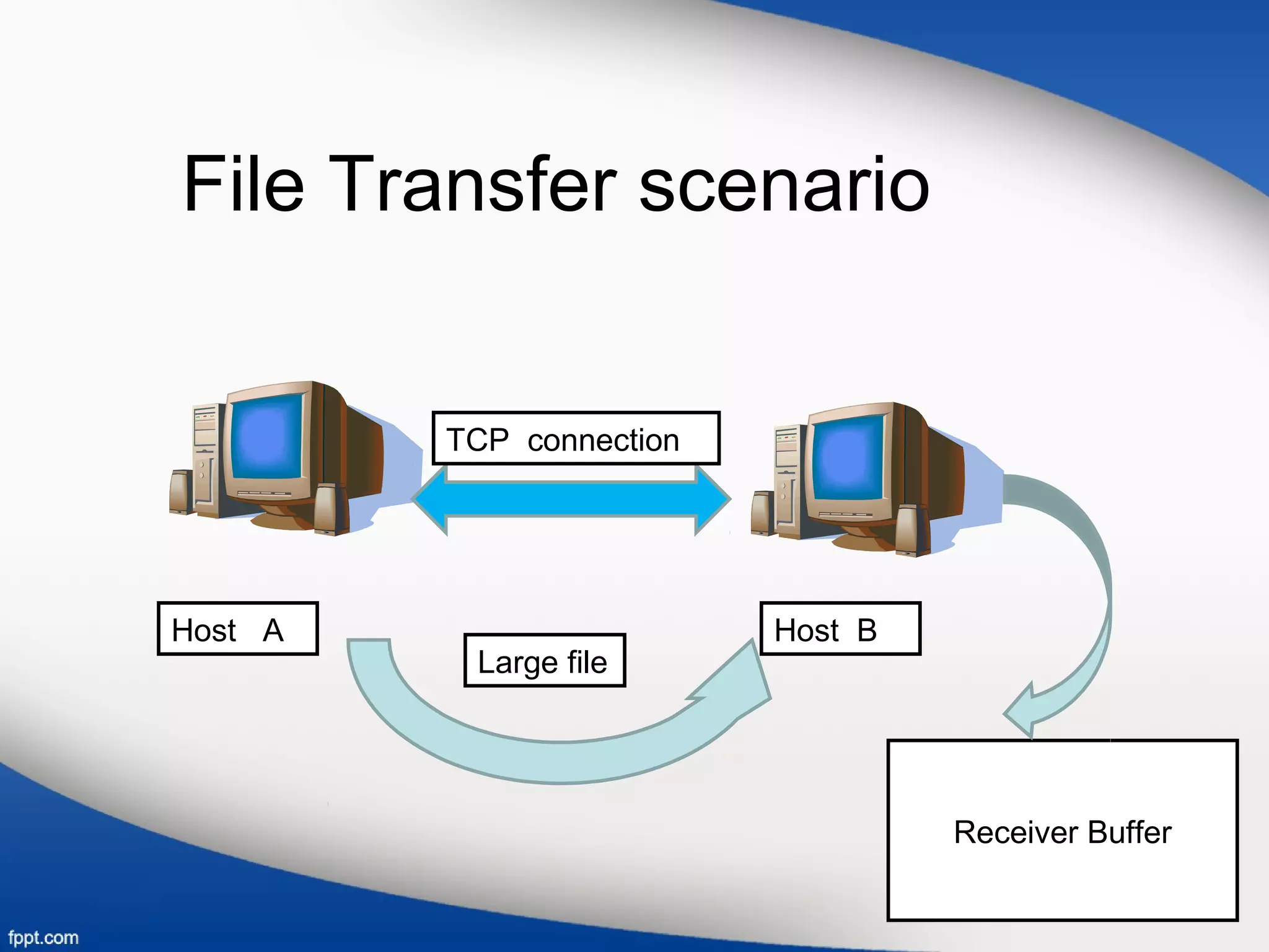
![• Variables used in this scenario:
1.LastByteRead
2.LastByteRcvd
• Receive window is represented by RcvWindow
• RcvWindow=RcvBuffer-[LastByteRcvd-LastByteRead]
• TCP is not allow the sender to overflow the allocated receiver
buffer.
• LastByteRcvd-LastByteRead <=RcvBuffer.
• Spare room is changes with time, RcvWindow is dynamic.](https://image.slidesharecdn.com/transportlayer-161107221039/75/Transport-layer-7-2048.jpg)