Tcp
•Download as DOCX, PDF•
0 likes•137 views

TCP provides several services to applications including process-to-process communication using port numbers, reliable stream delivery of data between processes, and full-duplex communication where data can flow in both directions simultaneously. TCP uses buffers, segments, checksums, acknowledgments, timeouts, and retransmissions to provide reliable data transmission. It establishes connections between processes, delivers data in-order as a stream, and ensures all data is received correctly through error control mechanisms.

Recommended
More Related Content
What's hot
What's hot (20)
Similar to Tcp
Similar to Tcp (20)
Recently uploaded
Recently uploaded (20)
Tcp
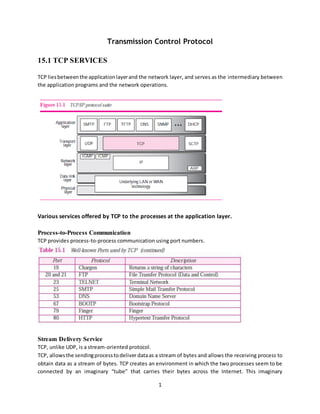
- 1. 1 Transmission Control Protocol 15.1 TCP SERVICES TCP liesbetweenthe applicationlayerand the network layer, and serves as the intermediary between the application programs and the network operations. Various services offered by TCP to the processes at the application layer. Process-to-Process Communication TCP provides process-to-process communication using port numbers. Stream Delivery Service TCP, unlike UDP, is a stream-oriented protocol. TCP, allowsthe sendingprocesstodeliver dataas a stream of bytes and allows the receiving process to obtain data as a stream of bytes. TCP creates an environment in which the two processes seem to be connected by an imaginary “tube” that carries their bytes across the Internet. This imaginary
- 2. 2 environment is depicted in Figure 15.2. The sending process produces (writes to) the stream of bytes and the receiving process consumes (reads from) them. Sending and Receiving Buffers Because the sending and the receiving processes may not necessarily write or read data at the same rate,TCP needsbuffersforstorage.There are twobuffers,the sending buffer and the receiving buffer, one for eachdirection. These buffers are necessaryforflow-anderror-control mechanismsusedbyTCP. Segments At the transportlayer,TCP groupsa numberof bytes together into a packet called a segment. TCP adds a header to each segment (for control purposes) and delivers the segment to the IP layer for transmission.The segmentsare encapsulatedinanIPdatagram and transmitted.Thisentire operationis transparent to the receiving process. Full-Duplex Communication TCP offers full-duplex service, where data can flow in both directions at the same time. Each TCP endpoint then has its own sending and receiving buffer, and segments move in both directions. Multiplexing and Demultiplexing TCP performs multiplexing at the sender and demultiplexing at the receiver. However, since TCP is a connection-oriented protocol, a connection needs to be established for each pair of processes. Connection-Oriented Service TCP, unlike UDP, is a connection-oriented protocol. Whena processat site A wantsto sendto and receive datafromanotherprocessat site B,the following three phases occur: 1. The two TCPs establish a virtual connection between them. 2. Data are exchanged in both directions. 3. The connection is terminated. The TCP segment is encapsulated in an IP datagram and can be sent out of order, or lost, or corrupted, and thenresent.Eachmay be routedovera differentpathto reach the destination.There is no physical connection. TCP creates a stream-oriented environment in which it accepts the responsibility of delivering the bytes in order to the other site.
- 3. 3 Reliable Service TCP isa reliable transportprotocol.Itusesan acknowledgmentmechanismto check the safe and sound arrival of data. 15.7 FLOW CONTROL Flow control balances the rate a producer creates data with the rate a consumer can use the data. Figure 15.24 shows unidirectional data transfer between a sender and a receiver; The figure showsthatdata travel fromthe sending process down to the sending TCP, from the sending TCP to the receiving TCP, and from receiving TCP up to the receiving process (paths 1, 2, and 3). Flow control feedbacks, however, are traveling from the receiving TCP to the sending TCP and from the sending TCP up to the sending process (paths 4 and 5). Opening and Closing Windows To achieve flowcontrol,TCP forces the sender and the receiver to adjust their window sizes, although the size of the bufferforbothpartiesisfixedwhenthe connectionis established. The opening, closing, and shrinking of the send window is controlled by the receiver. Shrinking of Windows The receive window cannot shrink. But the send window can shrink if the receiver defines a value for rwndthat resultsinshrinkingthe window.Some implementationsdonotallow the shrinkingof the send window. Window Shutdown The receivercantemporarilyshutdownthe window bysendingarwndof 0. This can happenif for some reason the receiver does not want to receive any data from the sender for a while. In this case, the
- 4. 4 sender does not actually shrink the size of the window, but stops sending data until a new advertisement has arrived. Silly Window Syndrome A serious problem can arise in the sliding window operation when either the sending application program createsdata slowlyorthe receivingapplicationprogramconsumesdataslowly,or both. Any of these situations results in the sending of data in very small segments, which reduces the efficiency of the operation. This problem is called the silly window syndrome. Syndrome Created by the Sender The sendingTCPmay create a sillywindow syndrome if itis serving an application program that creates data slowly, for example, 1 byte at a time. The application program writes 1 byte at a time into the buffer of the sending TCP. If the sending TCP does not have any specific instructions, it may create segmentscontaining1byte of data. The resultisa lot of 41-byte segmentsthat are traveling through an internet. The solutionistopreventthe sendingTCPfromsendingthe databyte bybyte.The sending TCP must be forced to wait and collect data to send in a larger block. How long should the sending TCP wait? If it waits too long, it may delay the process. If it does not wait long enough, it may end up sending small segments. Nagle found an elegant solution. Nagle’s Algorithm Nagle’s algorithm is simple: 1. The sending TCP sends the first piece of data it receives from the sending application program even if it is only 1 byte. 2. Aftersendingthe firstsegment,the sendingTCP accumulates data in the output buffer and waits until either the receiving TCP sends an acknowledgment or until enough data has accumulated to fill a maximum-size segment. At this time, the sending TCP can send the segment. 3. Step 2 is repeated for the rest of the transmission. Segment 3 is sent immediately if an acknowledgment is received for segment 2, or if enough data have accumulated to fill a maximum-size segment. The elegance of Nagle’salgorithmis in its simplicity and in the fact that it takes into account the speed of the applicationprogramthatcreatesthe data and the speedof the network that transports the data. If the application program is faster than the network, the segments are larger (maximum-size segments).If the application program is slower than the network, the segments are smaller (less than the maximum segment size). Syndrome Created by the Receiver The receiving TCP may create a silly window syndrome if it is serving an application program that consumes data slowly, for example, 1 byte at a time. Suppose that the sending application program creates data in blocks of 1 kilobyte, but the receiving application program consumes data 1 byte at a
- 5. 5 time.Alsosuppose thatthe inputbufferof the receiving TCP is 4 kilobytes. The sender sends the first 4 kilobytesof data.The receiverstoresitinitsbuffer.Now itsbuffer is full. It advertises a window size of zero,whichmeansthe sendershouldstopsendingdata.The receivingapplicationreadsthe first byte of data fromthe inputbufferof the receivingTCP.Now there is1 byte of space inthe incomingbuffer. The receiving TCP announces a window size of 1 byte, which means that the sending TCP, which is eagerly waitingtosenddata, takesthis advertisementasgoodnewsandsendsa segmentcarryingonly1 byte of data. The procedure will continue.One byte of data is consumed and a segment carrying 1 byte of data is sent. Again we have an efficiency problem and the silly window syndrome. Two solutions have been proposed to prevent the silly window syndrome created by an application program that consumes data slower than they arrive. Clark’s Solution Clark’ssolutionistosendan acknowledgmentassoonas the data arrive,butto announce a windowsize of zerountil eitherthere isenoughspace to accommodate a segment of maximum size or until at least half of the receive buffer is empty. Delayed Acknowledgment The secondsolutionistodelaysendingthe acknowledgment. This means that when a segment arrives, it is not acknowledged immediately. The receiver waits until there is a decent amount of space in its incomingbuffer before acknowledging the arrived segments. The delayed acknowledgment prevents the sendingTCPfromslidingitswindow.Afterthe sendingTCPhassentthe data in the window,itstops. This kills the syndrome. 15.8 ERROR CONTROL TCP isa reliable transportlayerprotocol.Thismeansthatan application program that delivers a stream of data to TCPreliesonTCP todeliverthe entire stream to the application program on the other end in order, without error, and without any part lost or duplicated. TCP provides reliability using error control. Error control includes mechanisms for detecting and resending corrupted segments, resending lost segments, storing out-oforder segments until missing segments arrive, and detecting and discarding duplicated segments. Error control in TCP is achieved through the use of three simple tools: checksum, acknowledgment, and time-out.
- 6. 6 Checksum Each segmentincludesachecksumfield,whichisusedtocheckfor a corruptedsegment. If a segment is corrupted,the segmentis discarded by the destination TCP and is considered as lost. TCP uses a 16-bit checksum that is mandatory in every segment. Acknowledgment TCP uses acknowledgments to confirm the receipt of data segments. Acknowledgment Type In the past, TCP used only one type of acknowledgment: cumulative acknowledgment. Today, some TCP implementations also use selective acknowledgment. Cumulative Acknowledgment (ACK) TCP wasoriginallydesignedtoacknowledgereceipt of segments cumulatively. The receiver advertises the next byte it expects to receive, ignoring all segments received and stored out of order. This is sometimes referred to as positive cumulative acknowledgment or ACK. The word “positive” indicates that no feedback is provided for discarded, lost, or duplicate segments. Selective Acknowledgment (SACK) SACKdoesnotreplace ACK,butreportsadditional information to the sender. A SACK reports a block of data that isout of order,and also a block of segments that is duplicated, i.e. received more than once. However, since there is no provision in the TCP header for adding this type of information, SACK is implemented as an option at the end of the TCP header. Generating Acknowledgments When does a receiver generate acknowledgments? Duringthe evolutionof TCP, several ruleshave beendefinedandusedby several implementations. We give the most common rules here. 1. When end A sends a data segment to end B, it must include (piggyback) an acknowledgment that gives the next sequence number it expects to receive. This rule decreases the number of segments needed and therefore reduces traffic. 2. When the receiver has no data to send and it receives an in-order segment (with expected sequence number) and the previous segment has already been acknowledged, the receiver delayssendinganACKsegmentuntilanothersegmentarrivesoruntil aperiodof time (normally 500 ms) has passed. 3. When a segment arrives with a sequence number that is expected by the receiver, and the previousin-ordersegmenthasnotbeenacknowledged,the receiverimmediately sends an ACK segment.Thispreventsthe unnecessary retransmissionof segmentsthatmaycreate congestion in the network. 4. When a segment arrives with an out-of-order sequence number that is higher than expected, the receiverimmediatelysendsanACK segment announcing the sequence number of the next expected segment. This leads to the fast retransmission of missing segments.
- 7. 7 5. When a missing segment arrives, the receiver sends an ACK segment to announce the next sequence number expected. This informs the receiver that segments reported missing have been received. 6. If a duplicate segment arrives, the receiver discards the segment, but immediately sends an acknowledgment indicating the next in-order segment expected. This solves some problems when an ACK segment itself is lost. Retransmission The heart of the errorcontrol mechanismisthe retransmissionof segments. When a segment is sent, it isstoredin a queue until itisacknowledged.Whenthe retransmissiontimerexpiresorwhenthe sender receives three duplicate ACKs for the first segment in the queue, that segment is retransmitted. Retransmission after RTO The sending TCP maintains one retransmission time-out (RTO) for each connection. When the timer matures,i.e.timesout,TCPsendsthe segmentinthe frontof the queue (the segmentwiththe smallest sequence number) and restarts the timer. Retransmission after Three Duplicate ACK Segments The previousrule aboutretransmissionof asegmentissufficientif the value of RTOis not large. To help throughputbyallowingsendertoretransmitsoonerthanwaitingfora time out, most implementations today follow the three duplicate ACKs rule and retransmit the missing segment immediately. This feature iscalledfastretransmission,andthe versionof TCPthatusesthisfeature is referred to as Reno. In this version, if three duplicate acknowledgments (i.e., an original ACK plus three exactly identical copies) arrive forasegment, the next segment is retransmitted without waiting for the time- out. Out-of-Order Segments TCP implementationstodaydonotdiscardout-of-ordersegments.Theystore themtemporarilyandflag them as out-of-order segments until the missing segments arrive. Note, however, that out-of-order segmentsare never delivered to the process. TCP guarantees that data are delivered to the process in order. 15.12 TCP PACKAGE TCP is a complex protocol. It is a stream-service, connection-oriented protocol with an involved state transition diagram. It uses flow and error control. The package involves tables called o transmission control blocks, o a set of timers, and three software modules:
- 8. 8 o a main module, o an input processing module, and o an output processing module. Figure 15.52 shows these five components and their interactions. Transmission Control Blocks (TCBs) TCP isa connection-orientedtransportprotocol.A connectionmaybe openfora long period of time. To control the connection,TCPusesa structure to holdinformation about each connection. This is called a transmission control block (TCB). Because at any time there can be several connections, TCP keeps an array of TCBs in the form of a table. The table is usually referred to as the TCB (see Figure 15.53). Timers The several timers in TCP need to keep track of its operations. Main Module The main module (Table 15.3) is invoked by an arriving TCP segment, a time-out event, or a message froman applicationprogram.Thisisa verycomplicatedmodule because the actiontobe takendepends on the current state of the TCP.
- 9. 9 To keepourdiscussionsimple,we use casestohandle the state.We have 11 states; we use 11 different cases. Each state is implemented as defined in the state transition diagram. The ESTABLISHED state needsfurtherexplanation. When TCP is in this state and data or an acknowledgment segment arrives, anothermodule,the inputprocessingmodule,iscalledtohandle the situation. Also,when TCP is in this state and a “send data” message is issued by an application program, another module, the output processing module, is called to handle the situation. Input Processing Module In our design, the input processing module handles all the details needed to process data or an acknowledgmentreceivedwhenTCPisin the ESTABLISHED state. This module sends an ACK if needed, takes care of the window size announcement, does error checking, and so on. Output Processing Module the outputprocessingmodule handlesall the detailsneededtosendout data receivedfrom application program when TCP is in the ESTABLISHED state. This module handles retransmission time-outs, persistent time-outs, and so on.
- 10. 10 11.4 RIP The Routing Information Protocol (RIP) is an intradomain (interior) routing protocol used inside an autonomous system. It is a very simple protocol based on distance vector routing. RIP implements distance vector routing directly with some considerations: 1. In an autonomoussystem,we are dealingwithroutersandnetworks(links),whatwasdescribed as a node. 2. The destinationinaroutingtable isa network,whichmeansthe first column defines a network address. 3 The metricusedby RIPis verysimple;the distance isdefined as the number of links (networks) that have to be used to reach the destination. For this reason, the metric in RIP is called a hop count. 4 Infinityisdefinedas16, whichmeansthat any route inan autonomous system using RIP cannot have more than 15 hops. 5 The next node column defines the address of the router to which the packet is to be sent to reach its destination. RIP Message Format The format of the RIP message is shown in Figure 11.11. Command. o This 8-bit field specifies the type of message: request (1) or response (2). Version. o This 8-bit field defines the version. Family.
- 11. 11 o This 16-bit field defines the family of the protocol used. For TCP/IP the value is 2. Network address. o The address field defines the address of the destination network. Distance. o This 32-bit field defines the hop count (cost) from the advertising router to the destination network. Requests and Responses RIP has two types of messages: 1. request and 2. response. Request A requestmessage issentbyarouter.A requestcanask about specific entries or all entries (see Figure 11.12). Response A response can be either solicited or unsolicited. A solicited response is sent only in answer to a request. It contains information about the destination specified in the corresponding request. An unsolicitedresponse,onthe otherhand,issentperiodically,every30secondsor whenthere is a change in the routing table. The response is sometimes called an update packet. Timers in RIP RIP uses three timers to support its operation (see Figure 11.14). 1. The periodic timer controls the sending of messages, 2. the expiration timer governs the validity of a route, and 3. the garbage collection timer advertises the failure of a route.
- 12. 12 Periodic Timer The periodictimercontrolsthe advertisingof regularupdate messages.Although the protocol specifies that thistimermustbe set to 30 s, the workingmodel usesarandom number between 25 and 35 s. This is to prevent any possible synchronization and therefore overload on an internet if routers update simultaneously. Each router hasone periodictimerthatisrandomlysetto a numberbetween25 and 35. It countsdown; when zero is reached, the update message is sent, and the timer is randomly set once again. Expiration Timer The expiration timer governs the validity of a route. When a router receives update information for a route, the expiration timer is set to 180 s for that particular route. Every time a new update for the route is received, the timer is reset. In normal situations this occurs every 30 s. However, if there is a problem on an internet and no update is received within the allotted 180 s, the route is consideredexpiredand the hop count of the route is set to 16, which means the destination is unreachable. Every route has its own expiration timer. Garbage Collection Timer Whenthe informationaboutaroute becomesinvalid,the routerdoesnotimmediately purge that route fromits table.Instead,itcontinuestoadvertise the route witha metric value of 16. At the same time, a timercalledthe garbage collectiontimerissetto120 s for thatroute.Whenthe countreaches zero, the route is purgedfromthe table.Thistimerallowsneighborstobecome aware of the invalidity of a route prior to purging. RIP Version 2 RIP version2was designedtoovercome some of the shortcomingsof version1.The designersof version 2 have notaugmentedthe lengthof the message for eachentry. Theyhave onlyreplacedthose fields in version 1 that were filled with 0s for the TCP/IP protocol with some new fields.
- 13. 13 Message Format Figure 11.15 showsthe format of a RIP version2 message.The new fieldsof thismessage are asfollows: Route tag. o Thisfieldcarriesinformationsuchasthe autonomoussystem number. It can be used to enable RIP to receive information from an interdomain routing protocol. Subnet mask. o This is a 4-byte field that carries the subnet mask (or prefix). This means that RIP2 supports classless addressing and CIDR. Next-hop address. o This field shows the address of the next hop. This is particularly useful if two autonomoussystemsshare anetwork(abackbone,forexample).Thenthe message can define the router, in the same autonomous system or another autonomous system, to which the packet next goes.
- 14. 14 11.6 OSPF The Open Shortest Path First (OSPF) protocol is an intradomain routing protocol based on link state routing. Its domain is also an autonomous system. Areas To handle routingefficientlyandinatimelymanner,OSPFdividesanautonomoussystemintoareas. An area is a collection of networks, hosts, and routers all contained within an autonomous system. An autonomous system can be divided into many different areas. All networks inside an area must be connected. Routersinside anareafloodthe area withroutinginformation.Atthe border of an area, special routerscalledareaborderrouterssummarize the informationaboutthe areaandsend it to other areas. Among the areas inside an autonomous system is a special area called the backbone; all of the areas inside anautonomoussystemmustbe connectedtothe backbone.Inotherwords,the backbone serves as a primaryarea and the otherareas as secondaryareas. The routersinside the backbone are calledthe backbone routers. Note that a backbone router can also be an area border router. If, because of some problem, the connectivity between a backbone and an area is broken, a virtual linkbetweenroutersmustbe createdby the administration to allow continuity of the functions of the backbone as the primary area. Each area has an area identification. The area identification of the backbone is zero. Figure 11.21 shows an autonomous system and its areas. Metric The OSPF protocol allows the administrator to assign a cost, called the metric, to each route. Types of Links
- 15. 15 In OSPF terminology, a connection is called a link. Four types of links have been defined: 1. point-to-point, 2. transient, 3. stub, and 4. virtual (see Figure 11.22). Point-to-Point Link A point-to-pointlinkconnectstworouterswithoutanyotherhostor routerin between. In other words, the purpose of the link (network) is just to connect the two routers. There is no need to assign a network address to this type of link. Transient Link A transient link is a network with several routers attached to it. The data can enter through any of the routers and leave through any router. Stub Link
- 16. 16 A stub link is a network that is connected to only one router. The data packets enter the network throughthissingle router and leave the network through this same router. This is a special case of the transient network. We can show this situation using the router as a node and using the designated router for the network. Virtual Link When the link between two routers is broken, the administration may create a virtual link between them using a longer path that probably goes through several routers. OSPF Packets OSPF uses five different types of packets: 1. hello, 2. database description, 3. link state request, 4. link state update, and 5. link state acknowledgment (see Figure 11.27). The most important one is the link state update that itself has five different kinds. Common Header
- 17. 17 All OSPF packets have the same common header (see Figure 11.28). Version. This 8-bit field defines the version of the OSPF protocol. Type. This 8-bit field defines the type of the packet. Message length.This16-bit fielddefines the length of the total message including the header. Source router IP address. This 32-bit field defines the IP address of the router that sends the packet. Area identification. This 32-bit field defines the area within which the routing takes place. Checksum. This field is used for error detection on the entire packet excluding the authentication type and authentication data field. Authentication type. This 16-bit field defines the authentication protocol used in this area. At this time, two types of authentication are defined: 0 for none and 1 for password. Authentication. This 64-bit field is the actual value of the authentication data. Link State Update Packet The link state update packet is the heart of the OSPF operation. It is used by a router to advertise the states of its links. The general format of the link state update packet is shown in Figure 11.29.
- 18. 18 11.8 BGP Border Gateway Protocol (BGP) is an interdomain routing protocol using path vector routing. Types of Autonomous Systems The Internet is divided into hierarchical domains called autonomous systems (ASs). For example, a large corporation that manages its own network and has full control over it is an autonomous system. A local ISP that provides services to local customers is an autonomous system. Note that a single organization may choose to have multiple ASs because of geographical spread, different providers (ISPs), or even some local obstacles. We can divide autonomous systems into three categories: 1. stub, 2. multihomed, and 3. transit. Stub AS A stubAS has onlyone connectiontoanotherAS.The interdomaindatatrafficina stub AS can be either createdor terminatedinthe AS. The hosts in the AS can send data traffic to other ASs. The hosts in the AS can receive data coming from hosts in other ASs. Data traffic, however, cannot pass through a stub AS. A stub AS is either a source or a sink. A good example of a stub AS is a small corporation or a small local ISP. Multihomed AS A multihomed AShasmore than one connectiontootherASs,but it is still only a source or sink for data traffic. It can receive data traffic from more than one AS. It can send data traffic to more than one AS, but there is no transient traffic. It does not allow data coming from one AS and going to another AS to pass through. Transit AS A transit AS is a multihomed AS that also allows transient traffic. Good examples of transit ASs are national and international ISPs (Internet backbones). BGP Sessions The exchange of routinginformationbetweentworoutersusingBGP takes place in a session. A session is a connection that is established between two BGP routers only for the sake of exchanging routing information. To create a reliable environment, BGP uses the services of TCP. Whena TCP connection iscreatedforBGP, it can lastfor a longtime,until something unusual happens. For this reason, BGP sessions are sometimes referred to as semipermanent connections. External and Internal BGP
- 19. 19 BGP can have two types of sessions: external BGP (E-BGP) and internal BGP (I-BGP) sessions. The E-BGP session is used to exchange information between two speaker nodes belonging to two different autonomous systems. The IBGP session, on the other hand, is used to exchange routing information between two routers inside an autonomous system. Figure 11.53 shows the idea. The session established between AS1 and AS2 is an E-BGP session. The two speaker routers exchange information they know about networks in the Internet. However, these two routers need to collect information from other routers in the autonomous systems. This is done using I-BGP sessions. Types of Packets BGP uses four different types of messages: 1. open, 2. update, 3. keepalive, and 4. notification (see Figure 11.54). Packet Format All BGP packets share the same common header.
- 20. 20 Open Message To create a neighborhood relationship, a router running BGP opens a TCP connection with a neighbor and sendsanopenmessage.If the neighbor accepts the neighborhood relationship, it responds with a keepalive message,whichmeansthata relationshiphas beenestablishedbetweenthe two routers. See Figure 11.56 for a depiction of the open message format. Version. o This 1-byte field defines the version of BGP. The current version is 4. My autonomous system. o This 2-byte field defines the autonomous system number. Hold time. o This2-byte fielddefines the maximum number of seconds that can elapse until one of the partiesreceivesakeepaliveor update message from the other. If a router does not receive one of these messagesduringthe holdtime period, it considers the other party dead. BGP identifier. o This 4-byte field defines the router that sends the open message. The router usually uses one of its IP addresses (because it is unique) for this purpose.
- 21. 21 Option length. o The openmessage maycontain some option parameters. In this case, this 1-byte field definesthe lengthof the total optionparameters.If there are nooptionparameters,the value of this field is zero. Option parameters. o The only option parameter defined so far is authentication. Update Message The update message is the heart of the BGP protocol. It is used by a router to withdraw destinations that have been advertised previously, announce a route to a new destination, or both. Keepalive Message The routers (called peers in BGP parlance) running the BGP protocols exchange keepalive messages regularly (before their hold time expires) to tell each other that they are alive. Notification Message A notificationmessage issentbya router whenever an error condition is detected or a router wants to close the connection.
- 22. 22 12.5 ROUTING PROTOCOLS Duringthe last fewdecades,several multicastroutingprotocolshave emerged.Some of these protocols are extensions of unicast routing protocols; some are totally new. Figure 12.21 shows the taxonomy of these protocols. Multicast Link State Routing: MOSPF Multicast link state routing is a direct extension of unicast routing and uses a source-based tree approach. For multicast routing, a node needs to revise the interpretation of state. A node advertises everygroupthat hasany loyal memberonthe link.Here the meaningof state is“what groups are active on this link.” The information about the group comes from IGMP. Multicast Open Shortest Path First (MOSPF) protocol is an extension of the OSPF protocol that uses multicastlinkstate routingtocreate source-basedtrees. The protocol requires a new link state update packet to associate the unicast address of a host with the group address or addresses the host is sponsoring. This packet is called the group membership LSA. MOSPF is a data-driven protocol; the first time an MOSPF router sees a datagram with a given source and group address, the router constructs the Dijkstra shortest path tree. CBT The Core-Based Tree (CBT) protocol is a group-shared protocol that uses a core as the root of the tree. The autonomous system is divided into regions, and a core (center router or rendezvous router) is chosen for each region. Formation of the Tree
- 23. 23 Afterthe rendezvouspoint is selected, every router is informed of the unicast address of the selected router.Each router withan inter created group then sends a unicast join message (similar to a grafting message) to show that it wants to join the group. This message passes through all routers that are located between the sender and the rendezvous router. Each intermediate router extracts the necessary information from the message, such asthe unicast address of the sender and the interface through which the packet has arrived, and forwards the message to the next router in the path. Whenthe rendezvousrouterhas receivedall joinmessagesfromeverymemberof the group,the tree is formed. Now every router knows its upstream router (the router that leads to the root) and the downstream router (the router that leads to the leaf). If a router wants to leave the group, it sends a leave message to its upstream router. The upstream routerremoves the link to that router from the tree and forwards the message to its upstream router, and so on. Figure 12.26 shows a group-shared tree with its rendezvous router. Sending Multicast Packets Afterformationof the tree,anysource (belongingtothe groupor not) can senda multicast packet to all membersof the group.It simplysendsthe packettothe rendezvous router,usingthe unicastaddress of the rendezvous router; the rendezvous router distributes the packet to all members of the group. Figure 12.27 shows how a host can send a multicast packet to all members of the group.
- 24. 24 PIM Protocol Independent Multicast (PIM) is the name given to two independent multicast routing protocols: 1. Protocol Independent Multicast, Dense Mode (PIM-DM) and 2. Protocol Independent Multicast, sparse Mode (PIM-SM). PIM-DM PIM-DM is used when there is a possibility that each router is involved in multicasting (dense mode). PIM-DM is a source-based tree routing protocol that uses RPF and pruning/grafting strategies for multicasting. It assumes that the autonomous system is using a unicast protocol and each router has a table that can findthe outgoing interface thathasanoptimal pathto a destination.Thisunicastprotocol can be a distance vector protocol (RIP) or link state protocol (OSPF). PIM-SM PIM-SM is used when there is a slight possibility that each router is involved in multicasting (sparse mode). PIM-SMisa group-sharedtree routingprotocol thathasa rendezvouspoint(RP) asthe source of the tree. Its operation is like CBT; however, it is simpler because it does not require acknowledgment froma joinmessage. One of the characteristicsof PIM-SMisthat it can switch from a group-shared tree strategy to a source-based tree strategy when necessary.