Downloaded 431 times
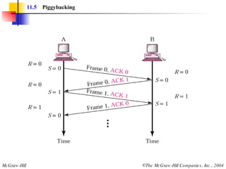
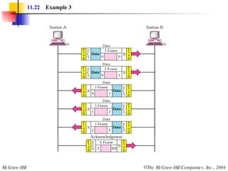
![Example 3 Figure 11.22 shows an exchange using piggybacking where is no error. Station A begins the exchange of information with an I-frame numbered 0 followed by another I-frame numbered 1. Station B piggybacks its acknowledgment of both frames onto an I-frame of its own. Station B’s first I-frame is also numbered 0 [N(S) field] and contains a 2 in its N(R) field, acknowledging the receipt of A’s frames 1 and 0 and indicating that it expects frame 2 to arrive next. Station B transmits its second and third I-frames (numbered 1 and 2) before accepting further frames from station A. Its N(R) information, therefore, has not changed: B frames 1 and 2 indicate that station B is still expecting A frame 2 to arrive next.](https://image.slidesharecdn.com/ch-11-090721210444-phpapp02/85/Ch-11-37-320.jpg)

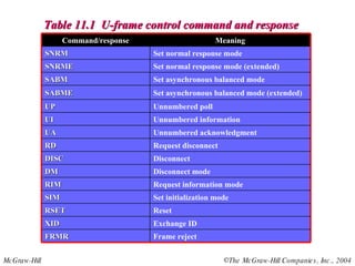
The document discusses various data link control protocols and HDLC frame formats. It covers topics like flow control, error control using automatic repeat request (ARQ), and different ARQ protocols including stop-and-wait, go-back-N, and selective repeat. It provides examples of how these protocols operate and calculates link utilization for different scenarios. It also discusses HDLC frame structures, types and fields, and the use of bit stuffing to ensure reliable data transmission.