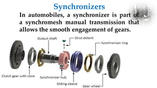
SlideShare a Scribd company logo
1. Gear Box
2. Vehicle Resistance
3. Types of Gear Boxes
4. Torque Converter
Contents
Functions of Gear Box
Gear Box - Introduction
 To provide variation in speed and torque.
 To provide neutral condition to the
vehicle.
 To provide reverse movement of vehicle
without changing the direction of rotation
of crankshaft.
1. Air Resistance
Resistance to vehicle motion
It depends upon speed of vehicle, speed and direction of wind and body
profile of the vehicle. It is taken to proportional to the square of the vehicle
speed. when a body moves, the air around it generates a resistance in the
opposite direction of the movement. For vehicles, air resistance affects the
comfort of the passengers, the fuel consumption, the stability, and many
other performance factors.
g
rr
aero
accel F
F
F
F
F 



2. Rolling Resistance
Resistance to vehicle motion
Composed primarily of
1. Resistance from tire deformation (90%)
2. Tire penetration and surface compression (
4%)
3. Tire slippage and air circulation around wheel
( 6%)
4. Wide range of factors affect total rolling
resistance
The magnitude of this force is Approximated as:
Rolling resistance of a vehicle is proportional to the component of
weight normal to the surface of travel
g
V
M
C
=
P rr
rr 


Mg
Frr  Mg
C
F rr
rr 
V
M
C
)
10
(2.72
=
P
V
M
C
3600
9.81
=
P
rr
3
-
rr
rr
rr













where:
Prr = power (kW)
Crr = coefficient of rolling resistance
M = mass (kg)
V = velocity (KpH)
3. Gradient Resistance
Resistance to vehicle motion
It depends upon slope of the road and mass of the vehicle. This
remains practically constant at all speed of the vehicle.
θg mg
Fg
θg
Composed of
◦ Gravitational force acting on the vehicle
g
g mg
F 
sin

g
g mg
F 
tan

G
g 

tan
mgG
Fg 
For small angles,
θg mg
Fg
θg
Resistance
Vehicle Speed
Steady State Demand Curve
Vehicle Speed vs. Engine Speed
 
o
crank
G
i
rN
V



60000
1
2
V = velocity , km/hr
r = wheel radius, m
Ncrank = crankshaft rpm
i = driveline slippage
GO = Overall gear reduction ratio
Tractive Effort
The force available at the contact between the
drive wheel tire and road is known as ‘tractive
effort’. The ability of the drive wheels to
transmit this effort without slipping is known
as ‘traction’. Hence usable tractive effort never
exceeds traction.
Characteristics Curves
Resistance
Vehicle Speed
Total Resistance
Rolling Resistance
Gradient Resistance
Air Resistance
Characteristics Curves
Tractive
Effort
Vehicle Speed
1st Gear
2nd Gear
3rd Gear
Characteristics Curves
Manual Transmission System
( Selective Gear Transmission )
Sliding Mesh Gear Box
Constant Mesh Gear Box
Synchromesh Gear Box
Sliding Mesh Gear Box
An obsolete type of
transmission or gearbox in
which the gears on the layshaft
are fixed to the shaft rigidly,
whereas the gears on the main
shaft can slide on it by means of
splines but are otherwise in
permanent rotational mesh
with the shaft.
Construction of Sliding Mesh Gearbox:
• The clutch shaft is connected to the engine output and rotates
when the engine rotates. A gear is mounted on the clutch shaft
which is connected with a gear of lay shaft.
• The lay shaft has several gears, one of which is connected to gear
of clutch shaft and others gears connect with different gear of
main shaft to obtain different gear ratio. Also, one gear in lay
shaft is reverse gear and has and idler gear which is placed
between the lay shaft gear and main shaft gear when operated.
• The main shaft has several gears and these gears can slide over
the main shaft to mesh with different gears of main shaft.
Working
• At first, the clutch shaft is driven by engine. It carries the engine output
and rotates in the same direction as that of engine. The gear connected
to the clutch shaft also rotates.
• As gear of clutch shaft rotates, the lay shaft gear which is connected to
the clutch shaft gear also rotates but in opposite direction.
• So the lay shaft rotates due to rotation of lay shaft gear that is rigidly
fixed in the lay shaft. Due to rotation of lay shaft other gears of lay shaft
also rotates as all the gears in lay shaft are rigidly fixed including the
reverse gear.
• The gears of main shaft are internally splined and the main shaft is also
splined, so the gears of main shaft can slide over it. The gear of main
shaft are shifted and meshed with different gears of lay shaft to obtain
different gear ratios required to face different road problem.
Advantages
1 Since only one gear is in mess in sliding mesh gearbox so less
fluctuating loads on shafts causing less vibration and noise unlike
the constant mesh gearbox in which all gears are in constant mesh.
2. Its efficiency is more than constant gearbox as only one gear is in
mess unlike the constant mesh gearbox in which all gears are in
constant mesh.
3. Its manufacturing is easy as compared to constant mesh gearbox.
4. Its mechanism is simple
Disadvantages
1 Only spur gears can be used as gears are not in constant mesh like
constant mesh gearbox in which helical or herringbone gears can be used.
2 More effort is required to engage the gear as the gear has to be slided in
sliding mesh gearbox unlike constant mesh gearbox where only dog clutch
has to be slided for engagement of different gears.
3 Less life of gear as more wear and tear of gear is caused in sliding mesh
gearbox due to friction.
4 It takes more time and money to replace the gears if the gearbox fails but
in constant mesh gearbox only dog clutches are to be replaced at failure
which takes less time and money.
Constant Mesh Gear Box
Constant mesh gearbox is a type of
Transmission in which all or most of
the gears are always in mesh with one
another, as opposed to a sliding-gear
transmission, in which engagement is
obtained by sliding some of the gears
along a shaft into mesh. In a constant-
mesh manual gearbox, Gear ratios are
selected by small Clutches that connect
the various gear sets to their shafts so
that power is transmitted through
them.
Dog Clutch: -
The dog clutch couples the lay shaft and main shaft by interference and not by
friction.
Dog clutches are used to transmit appropriate gear ratio to the main shaft or output
shaft by coming in interference with pair of gears with suitable gear ratio.
There are usually two dog clutches in a Constant Mesh Gear Box.
Working
Constant gear mesh gearbox employed
helical gears for power transmission. The
gears are rigidly fixed in the lay shaft. The
gears in output shaft rotates freely
without engaging with shaft, thus not
transmitting power. The gears in both
shafts are always meshed together.
To engage the gears with output shaft dog
clutch is used. the dog clutch is shifted by
the selector fork moved by gear lever. To
provide reverse gearing a idler gear is
used . It involves “Double Declutching”.
Double Declutching
With this method, instead of pushing
the clutch in once and shifting directly to
another gear, the driver first engages the
transmission in neutral before shifting to the
next gear.
Advantages
• The first and foremost benefit of the constant gear mesh is
the utilization of helical gears. The double helical gears and
the helical gears are extremely beneficial owing to their
quieter operating capabilities.
• There are various conditions which might cause harm. In
the case of constant mesh gearbox, any harm is suffered
entirely by the dog clutch teeth. The teeth belonging to the
gear wheels remain intact. This is not the case for sliding
mesh gear box.
• The other gear boxes are noisy and create an unwanted
friction.
Disadvantages
• It is less efficient than the others due to higher mesh teeth. Skill is
required for it.
• The double clutch mesh is required. This is required to have the
spinning movements of the shaft.
Synchromesh Gear Box
Synchromesh transmissions are a
further refined version of the
constant mesh system, although less
common. How it improves the
system is by adding another stage to
the process of connecting the gears
to the drive shaft through the dog
clutch.
Synchromesh gear box consists of a synchronizer
which resembles a doc clutch, the only variation
being that it first matches the speed of the driving
and driven gear and then meshes both the gears
A new component
was added to the
gears themselves
– the synchronizer
cone - and a
further moving
part called the
synchronizer ring
was introduced
that surrounded
the cone.
It splits the dog clutch in two – a gear fixed to the drive shaft called the synchronizer hub,
and a collar around the outside of it that could slide back and forth called the shift sleeve.
Salient features :-
 The clutch shaft and main shaft are in-line
while the lay shaft is parallel to them.*
 The main shaft gears are free to rotate , while
lay shaft gears are fixed to it.*
 The system incorporates a synchronizing
mechanism which allows the member first
brought into friction contact
Synchronizers
In automobiles, a synchronizer is part of
a synchromesh manual transmission that
allows the smooth engagement of gears.
Working
The synchronizer is
placed between two
gears. So, we can use one
unit for two gears. G1
and G2 are the ring-
shaped members which
are having the internal
tooth that fits onto the
external teeth. F1 and F2
are the sliding members
of the main shaft. H1, H2,
N1, N2, P1, P2, R1, R2 are
the friction surface
First gear
When the driver push or pull the gear lever in order to select the
first gear which gives the maximum torque and minimum speed
and is used to move the vehicle from its initial state ,the
synchromesh device attached with the pair of meshed gears
having biggest gear of the main shaft and smallest gear of the lay
shaft equalizes the speed of the shafts by making frictional
contact with the pair and finally the first gear is obtained.
Second gear
This is the gear having lower torque and higher speed than first
gear and is obtained when the pair of gears having second largest
gear of the main shaft and second smallest gear of the lay shaft is
meshed by the corresponding synchromesh device.
Third gear
This gear having higher speed and lower torque than
second gear is obtained when the corresponding
synchromesh device attached to the pair of gear having
intermediate size gear of main shaft and intermediate
size of gear of lay shaft makes contact.
Fourth gear
It is the second highest speed gear which is obtained
when the corresponding synchromesh device attached
to the pair of meshed gears having second smallest
gear of main shaft and second largest gear of the lay
shaft makes contact
Reverse gear
It is the gear that reverses the direction of the output
shaft which in turn reverse the direction of the vehicle
with the help of the idler gear which is usually fit in the
middle of the lay shaft and main shaft and is obtained
when the idler gear makes contact with the gears on
the main shaft and lay shaft.
Note – The reverse gear does not have any
synchronizer mechanism, so the gearbox shaft rotation
is completely stop before engaging the reverse gear.
Advantages:
Smooth and Noise free shifting of gears which is
most suitable for cars.
No loss of torque transmission from the engine to
the driving wheels during gear shifts.
Double clutching is not required.
Less vibration.
Quick shifting of gears without the risk of
damaging the gears.
Disadvantages:
 It is extortionate due to its high manufacturing cost
and the number of moving parts.
 When teeth make contact with the gear, the teeth
will fail to engage as they are spinning at different
speeds which causes a loud grinding sound as they
clatter together.
 Improper handling of gear may easily prone to
damage.
 Cannot handle higher loads.
Automatic Transmission System
An automatic transmission, also
called auto, self-shifting
transmission, n-speed
automatic (where n represents its
number of forward gear ratios),
or AT, is a type of motor
vehicle transmission that
automatically changes the gear
ratio as the vehicle moves, meaning
that the driver does not have to shift
the gears manually.
Epicyclic Gear Set
An Epicyclic gear train (also known
as planetary gear) consists of
two gears mounted so that the center of one
gear revolves around the center of the other.
A carrier connects the centers of the two
gears and rotates to carry one gear, called
the planet gear or planet pinion, around the
other, called the sun gear or sun wheel. The
planet and sun gears mesh so that
their pitch circles roll without slip. A point on
the pitch circle of the planet gear traces
an epicycloid curve. In this simplified case,
the sun gear is fixed and the planetary
gear(s) roll around the sun gear.
Mode Role Gears
1.Forward Fast
Output Speed
Driving P
Driven R
Stationary S
2.Forward Very
Fast Output
Speed
Driving P
Driven S
Stationary R
3.Forward slow
Output Speed
Driving R
Driven P
Stationary S
4.Forward Very
slow Output
Speed
Driving S
Driven P
Stationary R
Mode Role Gears
5.Reverse Slow
Output Speed
Driving S
Driven R
Stationary P
6.Reverse Fast
Output Speed
Driving R
Driven S
Stationary P
Torque Converter
• A torque converter is a
type of fluid coupling
used for transferring
rotating power to the
transmission from the
motor.
• It is achieved in an
automatic transmission
by a hydraulic clutch.
• Its main functions are:
• 1.It transfers the power from engine to the
transmission input shaft.
• 2. It drives the front pump of the transmission.
• 3. It isolates the engine from the load when the
vehicle is stationary.
• 4. It multiplies the torque of the engine and
transmits it to the transmission. It almost doubles
the output torque.
Functions of Torque Converter
Working of Torque Converter
It has three stages of operations –
1. Stall: The engine uses power to the impeller when the vehicle is stall
(stop), but the turbine can not rotate. This is when the car is stationary
and the driver has kept his foot on the brake paddle so that it does not
move. Maximum torque multiplication takes place during this condition.
The impeller moves faster as the driver removes the base from the brake
paddle and releases the accelerator paddle, allowing the motor to roll.
There is a greater difference in the pump speed from the turbine in this
situation. The speed of the rotor is significantly higher than that of the
turbine.
2. Acceleration: During acceleration, the speed of the turbine continues to
rise, but the impeller and turbine speed also differ greatly. The torque
multiplication is decreased as the turbine speed increases. The torque
multiplication is less than understanding conditions when the engine is
accelerated.
3. Coupling: This happens when the turbine reaches a speed of about 90%
of the impeller, which is known as the coupling point. The torque
multiplication is null and negative and the torque converter is compared
to a simple fluid relation. The locking clutch comes in at the coupling
point and locks the turbine to the converter’s impeller. This enables the
turbine and drives to move at the same speed. Only when the point is
reached is the clutch locked up. The stator also begins to rotate towards
the rotation of the rotor and of the turbine during the coupling.
Numericals
A
B C
D
F
E
G
H
78 mm
𝐺𝑒𝑎𝑟 𝑅𝑎𝑡𝑖𝑜 𝐺 =
𝑠𝑝𝑒𝑒𝑑 𝑜𝑓 𝑓𝑖𝑟𝑠𝑡 𝑑𝑟𝑖𝑣𝑒𝑟 𝑔𝑒𝑎𝑟
𝑠𝑝𝑒𝑒𝑑 𝑜𝑓 𝑙𝑎𝑠𝑡 𝑑𝑟𝑖𝑣𝑒𝑛 𝑔𝑒𝑎𝑟
=
𝑛𝑢𝑚𝑏𝑒𝑟 𝑜𝑓 𝑡𝑒𝑒𝑡𝑕 𝑜𝑛 𝑙𝑎𝑠𝑡 𝑑𝑟𝑖𝑣𝑒𝑛 𝑔𝑒𝑎𝑟
𝑛𝑢𝑚𝑏𝑒𝑟 𝑜𝑓 𝑡𝑒𝑒𝑡𝑕 𝑜𝑛 𝑓𝑖𝑟𝑠𝑡 𝑑𝑟𝑖𝑣𝑒𝑟 𝑔𝑒𝑎𝑟
𝑚 =
𝑑
𝑇
Numericals
A Sliding mesh type of gear box with forward speed only is to be
designed. The gearbox should have the following gear ratio
available approximately 1.0, 1.5, 2.5, 3.9. The Centre distance
between the lay shaft and main shaft is 78 mm and smallest gear is
to have at least 16 teeth with a module of 3.25mm. Calculate the
number of teeth of various gears and exact gear ratio.
A
B C
D
F
E
G
H
78 mm
A
B C
D
F
E
G
H
78 mm
rA + rB = rH+ rG = rF + rE = rD + rC = 78
𝑚 =
𝑑
𝑇
𝑚 =
2𝑟
𝑇
=
2𝑟𝐴
𝑇𝐴
rA =
m x TA
2
TA + TB = TH+ TG = TF + TE = TD + TC =
78 𝑥 2
𝑚
TA + TB = TH+ TG = TF + TE = TD + TC = 48
For First Gear (A-B-C-D)
G1 = 3.9 =
𝑁𝐴
𝑁𝐷
=
𝑇𝐷
𝑇𝐶
x
𝑇𝐵
𝑇𝐴
For Second Gear (A-B-E-F)
G2 = 2.5 =
𝑁𝐴
𝑁𝐹
=
𝑇𝐹
𝑇𝐸
x
𝑇𝐵
𝑇𝐴
For Third Gear (A-B-G-H)
G3 = 1.5 =
𝑁𝐴
𝑁𝐻
=
𝑇𝐻
𝑇𝐺
x
𝑇𝐵
𝑇𝐴
A
B C
D
F
E
G
H
78 mm
Numericals
A Sliding mesh type of gear box with forward speed is to be designed. The
gearbox should have the following gear ratio available approximately 1.0,
1.5, 2.5 And in reverse speed as 3.2. The Centre distance between the lay
shaft and main shaft is 84 mm and smallest gear is to have at least 12 teeth
with a module of 4 mm. Calculate the number of teeth of various gears and
exact gear ratio.
A
B G
H
F
E
C
D
84 mm
rA + rB = rF + rE = rD + rC = 48
𝑚 =
𝑑
𝑇
𝑚 =
2𝑟
𝑇
=
2𝑟𝐴
𝑇𝐴
rA =
m x TA
2
TA + TB = TF + TE = TD + TC =
84 𝑥 2
𝑚
TA + TB = TF + TE = TD + TC = 42
A
B G
H
F
E
C
D
84 mm
For Second Gear (A-B-C-D)
G1 = 3.9 =
𝑁𝐴
𝑁𝐷
=
𝑇𝐷
𝑇𝐶
x
𝑇𝐵
𝑇𝐴
For First Gear (A-B-E-F)
G2 = 2.5 =
𝑁𝐴
𝑁𝐹
=
𝑇𝐹
𝑇𝐸
x
𝑇𝐵
𝑇𝐴
For Third Gear
G3 = 1.0
A
B G
H
F
E
C
D
84 mm
For Reverse Gear
GR = 3.2=
𝑇𝐹
𝑇𝐺
x
𝑇𝐵
𝑇𝐴
From Eqn. 3
2.5 =
𝑁𝐴
𝑁𝐹
=
𝑇𝐹
𝑇𝐸
x
𝑇𝐵
𝑇𝐴
𝑇𝐹
𝑇𝐸
=1.875
From Eqn 1
TF = 27
TE = 15

More Related Content

What's hot

Clutch ppt
Clutch pptClutch ppt
Clutch ppt
ANIL SHARMA
 
2b9fc module iii steering system_ part-ii (2)
2b9fc module iii steering system_ part-ii (2)2b9fc module iii steering system_ part-ii (2)
2b9fc module iii steering system_ part-ii (2)
Tanvi Gautam
 
DUAL CLUTCH TRANSMISSION SYSTEM
DUAL CLUTCH TRANSMISSION SYSTEMDUAL CLUTCH TRANSMISSION SYSTEM
DUAL CLUTCH TRANSMISSION SYSTEM
nithishreddy1999
 
Automobiles steering systems
Automobiles steering systemsAutomobiles steering systems
Automobiles steering systems
Nitin Malviya
 
Operation of centrifugal clutch
Operation of centrifugal clutchOperation of centrifugal clutch
Operation of centrifugal clutch
Praveen Kumar Kushwah
 
Transmission system in an automobile
Transmission system in an automobileTransmission system in an automobile
Transmission system in an automobile
Aakash Varshney
 
Wheel Alignment
Wheel AlignmentWheel Alignment
Wheel Alignment
sandeephbtu14
 
Unit 4 helical gear
Unit 4 helical gearUnit 4 helical gear
Unit 4 helical gear
Dr. L K Bhagi
 
Supercharging and Turbocharging
Supercharging and TurbochargingSupercharging and Turbocharging
Supercharging and Turbocharging
PankajArvikar1
 
Gear design , classification advantages and disadvantages
Gear design , classification  advantages and disadvantages Gear design , classification  advantages and disadvantages
Gear design , classification advantages and disadvantages
Jashavant singh
 
Differential Gear Box
Differential Gear BoxDifferential Gear Box
Differential Gear Box
Surya Pratap Singh Rathore
 
Automobile Differential Unit
Automobile Differential Unit Automobile Differential Unit
Automobile Differential Unit
Sivaraman Kumarasamy
 
Types of Transmission
Types of TransmissionTypes of Transmission
Types of Transmission
NILESH MISHRA
 
3 axles
3 axles3 axles
Design of Transmission System- GEAR BOX
Design of Transmission System- GEAR BOXDesign of Transmission System- GEAR BOX
Design of Transmission System- GEAR BOX
Mohan2405
 
BASICS OF TRANSMISSION SYSTEM
BASICS OF TRANSMISSION SYSTEMBASICS OF TRANSMISSION SYSTEM
BASICS OF TRANSMISSION SYSTEM
Kartik Paliwal
 
Clutches - Working and Application
Clutches - Working and ApplicationClutches - Working and Application
Clutches - Working and Application
Utsav Jain
 
Four wheel steering system
Four wheel steering systemFour wheel steering system
Four wheel steering system
Thakur Singh
 
Gear train
Gear trainGear train
Gear Box and Torque Converter- CSVTU
Gear Box and Torque Converter- CSVTUGear Box and Torque Converter- CSVTU
Gear Box and Torque Converter- CSVTU
ManishRKSahu
 

What's hot (20)

Clutch ppt
Clutch pptClutch ppt
Clutch ppt
 
2b9fc module iii steering system_ part-ii (2)
2b9fc module iii steering system_ part-ii (2)2b9fc module iii steering system_ part-ii (2)
2b9fc module iii steering system_ part-ii (2)
 
DUAL CLUTCH TRANSMISSION SYSTEM
DUAL CLUTCH TRANSMISSION SYSTEMDUAL CLUTCH TRANSMISSION SYSTEM
DUAL CLUTCH TRANSMISSION SYSTEM
 
Automobiles steering systems
Automobiles steering systemsAutomobiles steering systems
Automobiles steering systems
 
Operation of centrifugal clutch
Operation of centrifugal clutchOperation of centrifugal clutch
Operation of centrifugal clutch
 
Transmission system in an automobile
Transmission system in an automobileTransmission system in an automobile
Transmission system in an automobile
 
Wheel Alignment
Wheel AlignmentWheel Alignment
Wheel Alignment
 
Unit 4 helical gear
Unit 4 helical gearUnit 4 helical gear
Unit 4 helical gear
 
Supercharging and Turbocharging
Supercharging and TurbochargingSupercharging and Turbocharging
Supercharging and Turbocharging
 
Gear design , classification advantages and disadvantages
Gear design , classification  advantages and disadvantages Gear design , classification  advantages and disadvantages
Gear design , classification advantages and disadvantages
 
Differential Gear Box
Differential Gear BoxDifferential Gear Box
Differential Gear Box
 
Automobile Differential Unit
Automobile Differential Unit Automobile Differential Unit
Automobile Differential Unit
 
Types of Transmission
Types of TransmissionTypes of Transmission
Types of Transmission
 
3 axles
3 axles3 axles
3 axles
 
Design of Transmission System- GEAR BOX
Design of Transmission System- GEAR BOXDesign of Transmission System- GEAR BOX
Design of Transmission System- GEAR BOX
 
BASICS OF TRANSMISSION SYSTEM
BASICS OF TRANSMISSION SYSTEMBASICS OF TRANSMISSION SYSTEM
BASICS OF TRANSMISSION SYSTEM
 
Clutches - Working and Application
Clutches - Working and ApplicationClutches - Working and Application
Clutches - Working and Application
 
Four wheel steering system
Four wheel steering systemFour wheel steering system
Four wheel steering system
 
Gear train
Gear trainGear train
Gear train
 
Gear Box and Torque Converter- CSVTU
Gear Box and Torque Converter- CSVTUGear Box and Torque Converter- CSVTU
Gear Box and Torque Converter- CSVTU
 

Similar to transmission.pdf

gear box - heart of automobile
gear box - heart of automobilegear box - heart of automobile
gear box - heart of automobile
naveen thamada
 
Transmission system
Transmission systemTransmission system
Transmission system
Ratnadeepsinh Jadeja
 
automobile power transmission
automobile power transmissionautomobile power transmission
automobile power transmission
Chetan Badsar
 
Vehicle Power transmission
Vehicle Power transmissionVehicle Power transmission
Vehicle Power transmission
Chetan Badsar
 
UNIT-III-TRANSMISSION SYSTEMS REAR AXLES
UNIT-III-TRANSMISSION SYSTEMS REAR AXLESUNIT-III-TRANSMISSION SYSTEMS REAR AXLES
UNIT-III-TRANSMISSION SYSTEMS REAR AXLES
DineshKumar4165
 
UNIT-III-TRANSMISSION SYSTEMS.pptx
UNIT-III-TRANSMISSION SYSTEMS.pptxUNIT-III-TRANSMISSION SYSTEMS.pptx
UNIT-III-TRANSMISSION SYSTEMS.pptx
ShanmathyAR2
 
UNIT-III-TRANSMISSION SYSTEMS.pptx
UNIT-III-TRANSMISSION SYSTEMS.pptxUNIT-III-TRANSMISSION SYSTEMS.pptx
UNIT-III-TRANSMISSION SYSTEMS.pptx
prakash0712
 
Mee404 lecture 03
Mee404 lecture 03Mee404 lecture 03
Mee404 lecture 03
Anubhav659
 
Gear box
Gear boxGear box
Gear box
deep388
 
Gear boxes
Gear boxesGear boxes
Transmission system_clutch
Transmission system_clutchTransmission system_clutch
Transmission system_clutch
Devendra Yadav
 
Manual transmission final
Manual transmission finalManual transmission final
Manual transmission final
Sagar Ahire
 
Disc Clutch
Disc ClutchDisc Clutch
Disc Clutch
Neel Patel
 
Mee404 lecture 05
Mee404 lecture 05Mee404 lecture 05
Mee404 lecture 05
Anubhav659
 
Transmission
Transmission Transmission
Transmission
UDITMODI5
 
Automobile transmission.pptx
Automobile transmission.pptxAutomobile transmission.pptx
Automobile transmission.pptx
ProfDrDileepK
 
Gear box classisfication
Gear box classisficationGear box classisfication
Gear box classisfication
Devendra Yadav
 
Transmission system of Automobiles
Transmission system of AutomobilesTransmission system of Automobiles
Transmission system of Automobiles
PraveenManickam2
 
gear and planetary drives
 gear and planetary drives gear and planetary drives
gear and planetary drives
Uludağ University
 
Auto unit 3
Auto unit 3Auto unit 3
Auto unit 3
Muthu Ram
 

Similar to transmission.pdf (20)

gear box - heart of automobile
gear box - heart of automobilegear box - heart of automobile
gear box - heart of automobile
 
Transmission system
Transmission systemTransmission system
Transmission system
 
automobile power transmission
automobile power transmissionautomobile power transmission
automobile power transmission
 
Vehicle Power transmission
Vehicle Power transmissionVehicle Power transmission
Vehicle Power transmission
 
UNIT-III-TRANSMISSION SYSTEMS REAR AXLES
UNIT-III-TRANSMISSION SYSTEMS REAR AXLESUNIT-III-TRANSMISSION SYSTEMS REAR AXLES
UNIT-III-TRANSMISSION SYSTEMS REAR AXLES
 
UNIT-III-TRANSMISSION SYSTEMS.pptx
UNIT-III-TRANSMISSION SYSTEMS.pptxUNIT-III-TRANSMISSION SYSTEMS.pptx
UNIT-III-TRANSMISSION SYSTEMS.pptx
 
UNIT-III-TRANSMISSION SYSTEMS.pptx
UNIT-III-TRANSMISSION SYSTEMS.pptxUNIT-III-TRANSMISSION SYSTEMS.pptx
UNIT-III-TRANSMISSION SYSTEMS.pptx
 
Mee404 lecture 03
Mee404 lecture 03Mee404 lecture 03
Mee404 lecture 03
 
Gear box
Gear boxGear box
Gear box
 
Gear boxes
Gear boxesGear boxes
Gear boxes
 
Transmission system_clutch
Transmission system_clutchTransmission system_clutch
Transmission system_clutch
 
Manual transmission final
Manual transmission finalManual transmission final
Manual transmission final
 
Disc Clutch
Disc ClutchDisc Clutch
Disc Clutch
 
Mee404 lecture 05
Mee404 lecture 05Mee404 lecture 05
Mee404 lecture 05
 
Transmission
Transmission Transmission
Transmission
 
Automobile transmission.pptx
Automobile transmission.pptxAutomobile transmission.pptx
Automobile transmission.pptx
 
Gear box classisfication
Gear box classisficationGear box classisfication
Gear box classisfication
 
Transmission system of Automobiles
Transmission system of AutomobilesTransmission system of Automobiles
Transmission system of Automobiles
 
gear and planetary drives
 gear and planetary drives gear and planetary drives
gear and planetary drives
 
Auto unit 3
Auto unit 3Auto unit 3
Auto unit 3
 

More from halilyldrm13

Chapter1ccccccccccccxxxxxxxxxxxxxxxxxxxxxxxxxxxxxxxx.pdf
Chapter1ccccccccccccxxxxxxxxxxxxxxxxxxxxxxxxxxxxxxxx.pdfChapter1ccccccccccccxxxxxxxxxxxxxxxxxxxxxxxxxxxxxxxx.pdf
Chapter1ccccccccccccxxxxxxxxxxxxxxxxxxxxxxxxxxxxxxxx.pdf
halilyldrm13
 
presentation1.pdf
presentation1.pdfpresentation1.pdf
presentation1.pdf
halilyldrm13
 
week 2.pdf
week 2.pdfweek 2.pdf
week 2.pdf
halilyldrm13
 
001End. Hid.ve Özel..ppt
001End. Hid.ve Özel..ppt001End. Hid.ve Özel..ppt
001End. Hid.ve Özel..ppt
halilyldrm13
 
016Manifold.ppt
016Manifold.ppt016Manifold.ppt
016Manifold.ppt
halilyldrm13
 
023OransalValfElektronikKontrol.ppt
023OransalValfElektronikKontrol.ppt023OransalValfElektronikKontrol.ppt
023OransalValfElektronikKontrol.ppt
halilyldrm13
 
021ServoValf.ppt
021ServoValf.ppt021ServoValf.ppt
021ServoValf.ppt
halilyldrm13
 
032manometre.ppt
032manometre.ppt032manometre.ppt
032manometre.ppt
halilyldrm13
 
006soğutucu.ppt
006soğutucu.ppt006soğutucu.ppt
006soğutucu.ppt
halilyldrm13
 
007pompa.ppt
007pompa.ppt007pompa.ppt
007pompa.ppt
halilyldrm13
 
008silindir.ppt
008silindir.ppt008silindir.ppt
008silindir.ppt
halilyldrm13
 
010Hidromotor.ppt
010Hidromotor.ppt010Hidromotor.ppt
010Hidromotor.ppt
halilyldrm13
 
000YönKontrolValfi.ppt
000YönKontrolValfi.ppt000YönKontrolValfi.ppt
000YönKontrolValfi.ppt
halilyldrm13
 
012BasınçKontrolValfi.ppt
012BasınçKontrolValfi.ppt012BasınçKontrolValfi.ppt
012BasınçKontrolValfi.ppt
halilyldrm13
 
013AkışKontrolValfi.ppt
013AkışKontrolValfi.ppt013AkışKontrolValfi.ppt
013AkışKontrolValfi.ppt
halilyldrm13
 
029YataklamaElemanlarıI.ppt
029YataklamaElemanlarıI.ppt029YataklamaElemanlarıI.ppt
029YataklamaElemanlarıI.ppt
halilyldrm13
 
030Akümülatör.ppt
030Akümülatör.ppt030Akümülatör.ppt
030Akümülatör.ppt
halilyldrm13
 
031Bağlantı elemanları.ppt
031Bağlantı elemanları.ppt031Bağlantı elemanları.ppt
031Bağlantı elemanları.ppt
halilyldrm13
 
036HidrolikBakım.ppt
036HidrolikBakım.ppt036HidrolikBakım.ppt
036HidrolikBakım.ppt
halilyldrm13
 
026YağlardaKirlilik.ppt
026YağlardaKirlilik.ppt026YağlardaKirlilik.ppt
026YağlardaKirlilik.ppt
halilyldrm13
 

More from halilyldrm13 (20)

Chapter1ccccccccccccxxxxxxxxxxxxxxxxxxxxxxxxxxxxxxxx.pdf
Chapter1ccccccccccccxxxxxxxxxxxxxxxxxxxxxxxxxxxxxxxx.pdfChapter1ccccccccccccxxxxxxxxxxxxxxxxxxxxxxxxxxxxxxxx.pdf
Chapter1ccccccccccccxxxxxxxxxxxxxxxxxxxxxxxxxxxxxxxx.pdf
 
presentation1.pdf
presentation1.pdfpresentation1.pdf
presentation1.pdf
 
week 2.pdf
week 2.pdfweek 2.pdf
week 2.pdf
 
001End. Hid.ve Özel..ppt
001End. Hid.ve Özel..ppt001End. Hid.ve Özel..ppt
001End. Hid.ve Özel..ppt
 
016Manifold.ppt
016Manifold.ppt016Manifold.ppt
016Manifold.ppt
 
023OransalValfElektronikKontrol.ppt
023OransalValfElektronikKontrol.ppt023OransalValfElektronikKontrol.ppt
023OransalValfElektronikKontrol.ppt
 
021ServoValf.ppt
021ServoValf.ppt021ServoValf.ppt
021ServoValf.ppt
 
032manometre.ppt
032manometre.ppt032manometre.ppt
032manometre.ppt
 
006soğutucu.ppt
006soğutucu.ppt006soğutucu.ppt
006soğutucu.ppt
 
007pompa.ppt
007pompa.ppt007pompa.ppt
007pompa.ppt
 
008silindir.ppt
008silindir.ppt008silindir.ppt
008silindir.ppt
 
010Hidromotor.ppt
010Hidromotor.ppt010Hidromotor.ppt
010Hidromotor.ppt
 
000YönKontrolValfi.ppt
000YönKontrolValfi.ppt000YönKontrolValfi.ppt
000YönKontrolValfi.ppt
 
012BasınçKontrolValfi.ppt
012BasınçKontrolValfi.ppt012BasınçKontrolValfi.ppt
012BasınçKontrolValfi.ppt
 
013AkışKontrolValfi.ppt
013AkışKontrolValfi.ppt013AkışKontrolValfi.ppt
013AkışKontrolValfi.ppt
 
029YataklamaElemanlarıI.ppt
029YataklamaElemanlarıI.ppt029YataklamaElemanlarıI.ppt
029YataklamaElemanlarıI.ppt
 
030Akümülatör.ppt
030Akümülatör.ppt030Akümülatör.ppt
030Akümülatör.ppt
 
031Bağlantı elemanları.ppt
031Bağlantı elemanları.ppt031Bağlantı elemanları.ppt
031Bağlantı elemanları.ppt
 
036HidrolikBakım.ppt
036HidrolikBakım.ppt036HidrolikBakım.ppt
036HidrolikBakım.ppt
 
026YağlardaKirlilik.ppt
026YağlardaKirlilik.ppt026YağlardaKirlilik.ppt
026YağlardaKirlilik.ppt
 

Recently uploaded

What Exactly Is The Common Rail Direct Injection System & How Does It Work
What Exactly Is The Common Rail Direct Injection System & How Does It WorkWhat Exactly Is The Common Rail Direct Injection System & How Does It Work
What Exactly Is The Common Rail Direct Injection System & How Does It Work
Motor Cars International
 
Empowering Limpopo Entrepreneurs Consulting SMEs.pptx
Empowering Limpopo Entrepreneurs  Consulting SMEs.pptxEmpowering Limpopo Entrepreneurs  Consulting SMEs.pptx
Empowering Limpopo Entrepreneurs Consulting SMEs.pptx
Precious Mvulane CA (SA),RA
 
一比一原版SDSU毕业证圣地亚哥州立大学毕业证成绩单如何办理
一比一原版SDSU毕业证圣地亚哥州立大学毕业证成绩单如何办理一比一原版SDSU毕业证圣地亚哥州立大学毕业证成绩单如何办理
一比一原版SDSU毕业证圣地亚哥州立大学毕业证成绩单如何办理
psavhef
 
Ec460b lc Excavator Volvo Service Repair.pdf
Ec460b lc Excavator Volvo Service Repair.pdfEc460b lc Excavator Volvo Service Repair.pdf
Ec460b lc Excavator Volvo Service Repair.pdf
Excavator
 
Wondering if Your Mercedes EIS is at Fault Here’s How to Tell
Wondering if Your Mercedes EIS is at Fault Here’s How to TellWondering if Your Mercedes EIS is at Fault Here’s How to Tell
Wondering if Your Mercedes EIS is at Fault Here’s How to Tell
Vic Auto Collision & Repair
 
What Does the PARKTRONIC Inoperative, See Owner's Manual Message Mean for You...
What Does the PARKTRONIC Inoperative, See Owner's Manual Message Mean for You...What Does the PARKTRONIC Inoperative, See Owner's Manual Message Mean for You...
What Does the PARKTRONIC Inoperative, See Owner's Manual Message Mean for You...
Autohaus Service and Sales
 
Antique Plastic Traders Company Profile
Antique Plastic Traders Company ProfileAntique Plastic Traders Company Profile
Antique Plastic Traders Company Profile
Antique Plastic Traders
 
Things to remember while upgrading the brakes of your car
Things to remember while upgrading the brakes of your carThings to remember while upgrading the brakes of your car
Things to remember while upgrading the brakes of your car
jennifermiller8137
 
Why Is Your BMW X3 Hood Not Responding To Release Commands
Why Is Your BMW X3 Hood Not Responding To Release CommandsWhy Is Your BMW X3 Hood Not Responding To Release Commands
Why Is Your BMW X3 Hood Not Responding To Release Commands
Dart Auto
 
一比一原版BC毕业证波士顿学院毕业证成绩单如何办理
一比一原版BC毕业证波士顿学院毕业证成绩单如何办理一比一原版BC毕业证波士顿学院毕业证成绩单如何办理
一比一原版BC毕业证波士顿学院毕业证成绩单如何办理
amvovau
 
Core technology of Hyundai Motor Group's EV platform 'E-GMP'
Core technology of Hyundai Motor Group's EV platform 'E-GMP'Core technology of Hyundai Motor Group's EV platform 'E-GMP'
Core technology of Hyundai Motor Group's EV platform 'E-GMP'
Hyundai Motor Group
 
Statistics5,c.xz,c.;c.;d.c;d;ssssss.pptx
Statistics5,c.xz,c.;c.;d.c;d;ssssss.pptxStatistics5,c.xz,c.;c.;d.c;d;ssssss.pptx
Statistics5,c.xz,c.;c.;d.c;d;ssssss.pptx
coc7987515756
 
5 Warning Signs Your BMW's Intelligent Battery Sensor Needs Attention
5 Warning Signs Your BMW's Intelligent Battery Sensor Needs Attention5 Warning Signs Your BMW's Intelligent Battery Sensor Needs Attention
5 Warning Signs Your BMW's Intelligent Battery Sensor Needs Attention
Bertini's German Motors
 
Ec330B Lc Excavator Volvo Service Repair.pdf
Ec330B Lc Excavator Volvo Service Repair.pdfEc330B Lc Excavator Volvo Service Repair.pdf
Ec330B Lc Excavator Volvo Service Repair.pdf
Excavator
 
gtyccccccccccccccccccccccccccccccccccccccccccccccccccccccc
gtycccccccccccccccccccccccccccccccccccccccccccccccccccccccgtyccccccccccccccccccccccccccccccccccccccccccccccccccccccc
gtyccccccccccccccccccccccccccccccccccccccccccccccccccccccc
4thzenzstar
 
Tyre Industrymarket overview with examples of CEAT
Tyre Industrymarket overview with examples of CEATTyre Industrymarket overview with examples of CEAT
Tyre Industrymarket overview with examples of CEAT
kshamashah95
 
What Causes 'Trans Failsafe Prog' to Trigger in BMW X5
What Causes 'Trans Failsafe Prog' to Trigger in BMW X5What Causes 'Trans Failsafe Prog' to Trigger in BMW X5
What Causes 'Trans Failsafe Prog' to Trigger in BMW X5
European Service Center
 
Why Isn't Your BMW X5's Comfort Access Functioning Properly Find Out Here
Why Isn't Your BMW X5's Comfort Access Functioning Properly Find Out HereWhy Isn't Your BMW X5's Comfort Access Functioning Properly Find Out Here
Why Isn't Your BMW X5's Comfort Access Functioning Properly Find Out Here
Masters European & Gapanese Auto Repair
 
What Does the Active Steering Malfunction Warning Mean for Your BMW
What Does the Active Steering Malfunction Warning Mean for Your BMWWhat Does the Active Steering Malfunction Warning Mean for Your BMW
What Does the Active Steering Malfunction Warning Mean for Your BMW
Tanner Motors
 

Recently uploaded (19)

What Exactly Is The Common Rail Direct Injection System & How Does It Work
What Exactly Is The Common Rail Direct Injection System & How Does It WorkWhat Exactly Is The Common Rail Direct Injection System & How Does It Work
What Exactly Is The Common Rail Direct Injection System & How Does It Work
 
Empowering Limpopo Entrepreneurs Consulting SMEs.pptx
Empowering Limpopo Entrepreneurs  Consulting SMEs.pptxEmpowering Limpopo Entrepreneurs  Consulting SMEs.pptx
Empowering Limpopo Entrepreneurs Consulting SMEs.pptx
 
一比一原版SDSU毕业证圣地亚哥州立大学毕业证成绩单如何办理
一比一原版SDSU毕业证圣地亚哥州立大学毕业证成绩单如何办理一比一原版SDSU毕业证圣地亚哥州立大学毕业证成绩单如何办理
一比一原版SDSU毕业证圣地亚哥州立大学毕业证成绩单如何办理
 
Ec460b lc Excavator Volvo Service Repair.pdf
Ec460b lc Excavator Volvo Service Repair.pdfEc460b lc Excavator Volvo Service Repair.pdf
Ec460b lc Excavator Volvo Service Repair.pdf
 
Wondering if Your Mercedes EIS is at Fault Here’s How to Tell
Wondering if Your Mercedes EIS is at Fault Here’s How to TellWondering if Your Mercedes EIS is at Fault Here’s How to Tell
Wondering if Your Mercedes EIS is at Fault Here’s How to Tell
 
What Does the PARKTRONIC Inoperative, See Owner's Manual Message Mean for You...
What Does the PARKTRONIC Inoperative, See Owner's Manual Message Mean for You...What Does the PARKTRONIC Inoperative, See Owner's Manual Message Mean for You...
What Does the PARKTRONIC Inoperative, See Owner's Manual Message Mean for You...
 
Antique Plastic Traders Company Profile
Antique Plastic Traders Company ProfileAntique Plastic Traders Company Profile
Antique Plastic Traders Company Profile
 
Things to remember while upgrading the brakes of your car
Things to remember while upgrading the brakes of your carThings to remember while upgrading the brakes of your car
Things to remember while upgrading the brakes of your car
 
Why Is Your BMW X3 Hood Not Responding To Release Commands
Why Is Your BMW X3 Hood Not Responding To Release CommandsWhy Is Your BMW X3 Hood Not Responding To Release Commands
Why Is Your BMW X3 Hood Not Responding To Release Commands
 
一比一原版BC毕业证波士顿学院毕业证成绩单如何办理
一比一原版BC毕业证波士顿学院毕业证成绩单如何办理一比一原版BC毕业证波士顿学院毕业证成绩单如何办理
一比一原版BC毕业证波士顿学院毕业证成绩单如何办理
 
Core technology of Hyundai Motor Group's EV platform 'E-GMP'
Core technology of Hyundai Motor Group's EV platform 'E-GMP'Core technology of Hyundai Motor Group's EV platform 'E-GMP'
Core technology of Hyundai Motor Group's EV platform 'E-GMP'
 
Statistics5,c.xz,c.;c.;d.c;d;ssssss.pptx
Statistics5,c.xz,c.;c.;d.c;d;ssssss.pptxStatistics5,c.xz,c.;c.;d.c;d;ssssss.pptx
Statistics5,c.xz,c.;c.;d.c;d;ssssss.pptx
 
5 Warning Signs Your BMW's Intelligent Battery Sensor Needs Attention
5 Warning Signs Your BMW's Intelligent Battery Sensor Needs Attention5 Warning Signs Your BMW's Intelligent Battery Sensor Needs Attention
5 Warning Signs Your BMW's Intelligent Battery Sensor Needs Attention
 
Ec330B Lc Excavator Volvo Service Repair.pdf
Ec330B Lc Excavator Volvo Service Repair.pdfEc330B Lc Excavator Volvo Service Repair.pdf
Ec330B Lc Excavator Volvo Service Repair.pdf
 
gtyccccccccccccccccccccccccccccccccccccccccccccccccccccccc
gtycccccccccccccccccccccccccccccccccccccccccccccccccccccccgtyccccccccccccccccccccccccccccccccccccccccccccccccccccccc
gtyccccccccccccccccccccccccccccccccccccccccccccccccccccccc
 
Tyre Industrymarket overview with examples of CEAT
Tyre Industrymarket overview with examples of CEATTyre Industrymarket overview with examples of CEAT
Tyre Industrymarket overview with examples of CEAT
 
What Causes 'Trans Failsafe Prog' to Trigger in BMW X5
What Causes 'Trans Failsafe Prog' to Trigger in BMW X5What Causes 'Trans Failsafe Prog' to Trigger in BMW X5
What Causes 'Trans Failsafe Prog' to Trigger in BMW X5
 
Why Isn't Your BMW X5's Comfort Access Functioning Properly Find Out Here
Why Isn't Your BMW X5's Comfort Access Functioning Properly Find Out HereWhy Isn't Your BMW X5's Comfort Access Functioning Properly Find Out Here
Why Isn't Your BMW X5's Comfort Access Functioning Properly Find Out Here
 
What Does the Active Steering Malfunction Warning Mean for Your BMW
What Does the Active Steering Malfunction Warning Mean for Your BMWWhat Does the Active Steering Malfunction Warning Mean for Your BMW
What Does the Active Steering Malfunction Warning Mean for Your BMW
 

transmission.pdf

  • 1. 1. Gear Box 2. Vehicle Resistance 3. Types of Gear Boxes 4. Torque Converter Contents
  • 2. Functions of Gear Box Gear Box - Introduction  To provide variation in speed and torque.  To provide neutral condition to the vehicle.  To provide reverse movement of vehicle without changing the direction of rotation of crankshaft.
  • 3. 1. Air Resistance Resistance to vehicle motion It depends upon speed of vehicle, speed and direction of wind and body profile of the vehicle. It is taken to proportional to the square of the vehicle speed. when a body moves, the air around it generates a resistance in the opposite direction of the movement. For vehicles, air resistance affects the comfort of the passengers, the fuel consumption, the stability, and many other performance factors. g rr aero accel F F F F F    
  • 4. 2. Rolling Resistance Resistance to vehicle motion Composed primarily of 1. Resistance from tire deformation (90%) 2. Tire penetration and surface compression ( 4%) 3. Tire slippage and air circulation around wheel ( 6%) 4. Wide range of factors affect total rolling resistance
  • 5. The magnitude of this force is Approximated as: Rolling resistance of a vehicle is proportional to the component of weight normal to the surface of travel g V M C = P rr rr    Mg Frr  Mg C F rr rr  V M C ) 10 (2.72 = P V M C 3600 9.81 = P rr 3 - rr rr rr              where: Prr = power (kW) Crr = coefficient of rolling resistance M = mass (kg) V = velocity (KpH)
  • 6. 3. Gradient Resistance Resistance to vehicle motion It depends upon slope of the road and mass of the vehicle. This remains practically constant at all speed of the vehicle. θg mg Fg θg Composed of ◦ Gravitational force acting on the vehicle g g mg F  sin 
  • 7. g g mg F  tan  G g   tan mgG Fg  For small angles, θg mg Fg θg
  • 9. Vehicle Speed vs. Engine Speed   o crank G i rN V    60000 1 2 V = velocity , km/hr r = wheel radius, m Ncrank = crankshaft rpm i = driveline slippage GO = Overall gear reduction ratio
  • 10. Tractive Effort The force available at the contact between the drive wheel tire and road is known as ‘tractive effort’. The ability of the drive wheels to transmit this effort without slipping is known as ‘traction’. Hence usable tractive effort never exceeds traction.
  • 11.
  • 12. Characteristics Curves Resistance Vehicle Speed Total Resistance Rolling Resistance Gradient Resistance Air Resistance
  • 15. Manual Transmission System ( Selective Gear Transmission ) Sliding Mesh Gear Box Constant Mesh Gear Box Synchromesh Gear Box
  • 16. Sliding Mesh Gear Box An obsolete type of transmission or gearbox in which the gears on the layshaft are fixed to the shaft rigidly, whereas the gears on the main shaft can slide on it by means of splines but are otherwise in permanent rotational mesh with the shaft.
  • 17. Construction of Sliding Mesh Gearbox: • The clutch shaft is connected to the engine output and rotates when the engine rotates. A gear is mounted on the clutch shaft which is connected with a gear of lay shaft. • The lay shaft has several gears, one of which is connected to gear of clutch shaft and others gears connect with different gear of main shaft to obtain different gear ratio. Also, one gear in lay shaft is reverse gear and has and idler gear which is placed between the lay shaft gear and main shaft gear when operated. • The main shaft has several gears and these gears can slide over the main shaft to mesh with different gears of main shaft.
  • 18. Working • At first, the clutch shaft is driven by engine. It carries the engine output and rotates in the same direction as that of engine. The gear connected to the clutch shaft also rotates. • As gear of clutch shaft rotates, the lay shaft gear which is connected to the clutch shaft gear also rotates but in opposite direction. • So the lay shaft rotates due to rotation of lay shaft gear that is rigidly fixed in the lay shaft. Due to rotation of lay shaft other gears of lay shaft also rotates as all the gears in lay shaft are rigidly fixed including the reverse gear. • The gears of main shaft are internally splined and the main shaft is also splined, so the gears of main shaft can slide over it. The gear of main shaft are shifted and meshed with different gears of lay shaft to obtain different gear ratios required to face different road problem.
  • 19.
  • 20. Advantages 1 Since only one gear is in mess in sliding mesh gearbox so less fluctuating loads on shafts causing less vibration and noise unlike the constant mesh gearbox in which all gears are in constant mesh. 2. Its efficiency is more than constant gearbox as only one gear is in mess unlike the constant mesh gearbox in which all gears are in constant mesh. 3. Its manufacturing is easy as compared to constant mesh gearbox. 4. Its mechanism is simple
  • 21. Disadvantages 1 Only spur gears can be used as gears are not in constant mesh like constant mesh gearbox in which helical or herringbone gears can be used. 2 More effort is required to engage the gear as the gear has to be slided in sliding mesh gearbox unlike constant mesh gearbox where only dog clutch has to be slided for engagement of different gears. 3 Less life of gear as more wear and tear of gear is caused in sliding mesh gearbox due to friction. 4 It takes more time and money to replace the gears if the gearbox fails but in constant mesh gearbox only dog clutches are to be replaced at failure which takes less time and money.
  • 22. Constant Mesh Gear Box Constant mesh gearbox is a type of Transmission in which all or most of the gears are always in mesh with one another, as opposed to a sliding-gear transmission, in which engagement is obtained by sliding some of the gears along a shaft into mesh. In a constant- mesh manual gearbox, Gear ratios are selected by small Clutches that connect the various gear sets to their shafts so that power is transmitted through them.
  • 23.
  • 24.
  • 25. Dog Clutch: - The dog clutch couples the lay shaft and main shaft by interference and not by friction. Dog clutches are used to transmit appropriate gear ratio to the main shaft or output shaft by coming in interference with pair of gears with suitable gear ratio. There are usually two dog clutches in a Constant Mesh Gear Box.
  • 26. Working Constant gear mesh gearbox employed helical gears for power transmission. The gears are rigidly fixed in the lay shaft. The gears in output shaft rotates freely without engaging with shaft, thus not transmitting power. The gears in both shafts are always meshed together. To engage the gears with output shaft dog clutch is used. the dog clutch is shifted by the selector fork moved by gear lever. To provide reverse gearing a idler gear is used . It involves “Double Declutching”.
  • 27. Double Declutching With this method, instead of pushing the clutch in once and shifting directly to another gear, the driver first engages the transmission in neutral before shifting to the next gear.
  • 28.
  • 29. Advantages • The first and foremost benefit of the constant gear mesh is the utilization of helical gears. The double helical gears and the helical gears are extremely beneficial owing to their quieter operating capabilities. • There are various conditions which might cause harm. In the case of constant mesh gearbox, any harm is suffered entirely by the dog clutch teeth. The teeth belonging to the gear wheels remain intact. This is not the case for sliding mesh gear box. • The other gear boxes are noisy and create an unwanted friction.
  • 30. Disadvantages • It is less efficient than the others due to higher mesh teeth. Skill is required for it. • The double clutch mesh is required. This is required to have the spinning movements of the shaft.
  • 31. Synchromesh Gear Box Synchromesh transmissions are a further refined version of the constant mesh system, although less common. How it improves the system is by adding another stage to the process of connecting the gears to the drive shaft through the dog clutch. Synchromesh gear box consists of a synchronizer which resembles a doc clutch, the only variation being that it first matches the speed of the driving and driven gear and then meshes both the gears
  • 32. A new component was added to the gears themselves – the synchronizer cone - and a further moving part called the synchronizer ring was introduced that surrounded the cone. It splits the dog clutch in two – a gear fixed to the drive shaft called the synchronizer hub, and a collar around the outside of it that could slide back and forth called the shift sleeve.
  • 33. Salient features :-  The clutch shaft and main shaft are in-line while the lay shaft is parallel to them.*  The main shaft gears are free to rotate , while lay shaft gears are fixed to it.*  The system incorporates a synchronizing mechanism which allows the member first brought into friction contact
  • 34. Synchronizers In automobiles, a synchronizer is part of a synchromesh manual transmission that allows the smooth engagement of gears.
  • 35. Working The synchronizer is placed between two gears. So, we can use one unit for two gears. G1 and G2 are the ring- shaped members which are having the internal tooth that fits onto the external teeth. F1 and F2 are the sliding members of the main shaft. H1, H2, N1, N2, P1, P2, R1, R2 are the friction surface
  • 36. First gear When the driver push or pull the gear lever in order to select the first gear which gives the maximum torque and minimum speed and is used to move the vehicle from its initial state ,the synchromesh device attached with the pair of meshed gears having biggest gear of the main shaft and smallest gear of the lay shaft equalizes the speed of the shafts by making frictional contact with the pair and finally the first gear is obtained. Second gear This is the gear having lower torque and higher speed than first gear and is obtained when the pair of gears having second largest gear of the main shaft and second smallest gear of the lay shaft is meshed by the corresponding synchromesh device.
  • 37. Third gear This gear having higher speed and lower torque than second gear is obtained when the corresponding synchromesh device attached to the pair of gear having intermediate size gear of main shaft and intermediate size of gear of lay shaft makes contact. Fourth gear It is the second highest speed gear which is obtained when the corresponding synchromesh device attached to the pair of meshed gears having second smallest gear of main shaft and second largest gear of the lay shaft makes contact
  • 38. Reverse gear It is the gear that reverses the direction of the output shaft which in turn reverse the direction of the vehicle with the help of the idler gear which is usually fit in the middle of the lay shaft and main shaft and is obtained when the idler gear makes contact with the gears on the main shaft and lay shaft. Note – The reverse gear does not have any synchronizer mechanism, so the gearbox shaft rotation is completely stop before engaging the reverse gear.
  • 39. Advantages: Smooth and Noise free shifting of gears which is most suitable for cars. No loss of torque transmission from the engine to the driving wheels during gear shifts. Double clutching is not required. Less vibration. Quick shifting of gears without the risk of damaging the gears.
  • 40. Disadvantages:  It is extortionate due to its high manufacturing cost and the number of moving parts.  When teeth make contact with the gear, the teeth will fail to engage as they are spinning at different speeds which causes a loud grinding sound as they clatter together.  Improper handling of gear may easily prone to damage.  Cannot handle higher loads.
  • 41. Automatic Transmission System An automatic transmission, also called auto, self-shifting transmission, n-speed automatic (where n represents its number of forward gear ratios), or AT, is a type of motor vehicle transmission that automatically changes the gear ratio as the vehicle moves, meaning that the driver does not have to shift the gears manually.
  • 42. Epicyclic Gear Set An Epicyclic gear train (also known as planetary gear) consists of two gears mounted so that the center of one gear revolves around the center of the other. A carrier connects the centers of the two gears and rotates to carry one gear, called the planet gear or planet pinion, around the other, called the sun gear or sun wheel. The planet and sun gears mesh so that their pitch circles roll without slip. A point on the pitch circle of the planet gear traces an epicycloid curve. In this simplified case, the sun gear is fixed and the planetary gear(s) roll around the sun gear.
  • 43. Mode Role Gears 1.Forward Fast Output Speed Driving P Driven R Stationary S 2.Forward Very Fast Output Speed Driving P Driven S Stationary R 3.Forward slow Output Speed Driving R Driven P Stationary S 4.Forward Very slow Output Speed Driving S Driven P Stationary R
  • 44. Mode Role Gears 5.Reverse Slow Output Speed Driving S Driven R Stationary P 6.Reverse Fast Output Speed Driving R Driven S Stationary P
  • 45. Torque Converter • A torque converter is a type of fluid coupling used for transferring rotating power to the transmission from the motor. • It is achieved in an automatic transmission by a hydraulic clutch.
  • 46. • Its main functions are: • 1.It transfers the power from engine to the transmission input shaft. • 2. It drives the front pump of the transmission. • 3. It isolates the engine from the load when the vehicle is stationary. • 4. It multiplies the torque of the engine and transmits it to the transmission. It almost doubles the output torque. Functions of Torque Converter
  • 47. Working of Torque Converter It has three stages of operations – 1. Stall: The engine uses power to the impeller when the vehicle is stall (stop), but the turbine can not rotate. This is when the car is stationary and the driver has kept his foot on the brake paddle so that it does not move. Maximum torque multiplication takes place during this condition. The impeller moves faster as the driver removes the base from the brake paddle and releases the accelerator paddle, allowing the motor to roll. There is a greater difference in the pump speed from the turbine in this situation. The speed of the rotor is significantly higher than that of the turbine.
  • 48. 2. Acceleration: During acceleration, the speed of the turbine continues to rise, but the impeller and turbine speed also differ greatly. The torque multiplication is decreased as the turbine speed increases. The torque multiplication is less than understanding conditions when the engine is accelerated. 3. Coupling: This happens when the turbine reaches a speed of about 90% of the impeller, which is known as the coupling point. The torque multiplication is null and negative and the torque converter is compared to a simple fluid relation. The locking clutch comes in at the coupling point and locks the turbine to the converter’s impeller. This enables the turbine and drives to move at the same speed. Only when the point is reached is the clutch locked up. The stator also begins to rotate towards the rotation of the rotor and of the turbine during the coupling.
  • 49. Numericals A B C D F E G H 78 mm 𝐺𝑒𝑎𝑟 𝑅𝑎𝑡𝑖𝑜 𝐺 = 𝑠𝑝𝑒𝑒𝑑 𝑜𝑓 𝑓𝑖𝑟𝑠𝑡 𝑑𝑟𝑖𝑣𝑒𝑟 𝑔𝑒𝑎𝑟 𝑠𝑝𝑒𝑒𝑑 𝑜𝑓 𝑙𝑎𝑠𝑡 𝑑𝑟𝑖𝑣𝑒𝑛 𝑔𝑒𝑎𝑟 = 𝑛𝑢𝑚𝑏𝑒𝑟 𝑜𝑓 𝑡𝑒𝑒𝑡𝑕 𝑜𝑛 𝑙𝑎𝑠𝑡 𝑑𝑟𝑖𝑣𝑒𝑛 𝑔𝑒𝑎𝑟 𝑛𝑢𝑚𝑏𝑒𝑟 𝑜𝑓 𝑡𝑒𝑒𝑡𝑕 𝑜𝑛 𝑓𝑖𝑟𝑠𝑡 𝑑𝑟𝑖𝑣𝑒𝑟 𝑔𝑒𝑎𝑟 𝑚 = 𝑑 𝑇
  • 50. Numericals A Sliding mesh type of gear box with forward speed only is to be designed. The gearbox should have the following gear ratio available approximately 1.0, 1.5, 2.5, 3.9. The Centre distance between the lay shaft and main shaft is 78 mm and smallest gear is to have at least 16 teeth with a module of 3.25mm. Calculate the number of teeth of various gears and exact gear ratio. A B C D F E G H 78 mm
  • 51. A B C D F E G H 78 mm rA + rB = rH+ rG = rF + rE = rD + rC = 78 𝑚 = 𝑑 𝑇 𝑚 = 2𝑟 𝑇 = 2𝑟𝐴 𝑇𝐴 rA = m x TA 2 TA + TB = TH+ TG = TF + TE = TD + TC = 78 𝑥 2 𝑚 TA + TB = TH+ TG = TF + TE = TD + TC = 48
  • 52. For First Gear (A-B-C-D) G1 = 3.9 = 𝑁𝐴 𝑁𝐷 = 𝑇𝐷 𝑇𝐶 x 𝑇𝐵 𝑇𝐴 For Second Gear (A-B-E-F) G2 = 2.5 = 𝑁𝐴 𝑁𝐹 = 𝑇𝐹 𝑇𝐸 x 𝑇𝐵 𝑇𝐴 For Third Gear (A-B-G-H) G3 = 1.5 = 𝑁𝐴 𝑁𝐻 = 𝑇𝐻 𝑇𝐺 x 𝑇𝐵 𝑇𝐴 A B C D F E G H 78 mm
  • 53.
  • 54. Numericals A Sliding mesh type of gear box with forward speed is to be designed. The gearbox should have the following gear ratio available approximately 1.0, 1.5, 2.5 And in reverse speed as 3.2. The Centre distance between the lay shaft and main shaft is 84 mm and smallest gear is to have at least 12 teeth with a module of 4 mm. Calculate the number of teeth of various gears and exact gear ratio. A B G H F E C D 84 mm
  • 55. rA + rB = rF + rE = rD + rC = 48 𝑚 = 𝑑 𝑇 𝑚 = 2𝑟 𝑇 = 2𝑟𝐴 𝑇𝐴 rA = m x TA 2 TA + TB = TF + TE = TD + TC = 84 𝑥 2 𝑚 TA + TB = TF + TE = TD + TC = 42 A B G H F E C D 84 mm
  • 56. For Second Gear (A-B-C-D) G1 = 3.9 = 𝑁𝐴 𝑁𝐷 = 𝑇𝐷 𝑇𝐶 x 𝑇𝐵 𝑇𝐴 For First Gear (A-B-E-F) G2 = 2.5 = 𝑁𝐴 𝑁𝐹 = 𝑇𝐹 𝑇𝐸 x 𝑇𝐵 𝑇𝐴 For Third Gear G3 = 1.0 A B G H F E C D 84 mm For Reverse Gear GR = 3.2= 𝑇𝐹 𝑇𝐺 x 𝑇𝐵 𝑇𝐴
  • 57. From Eqn. 3 2.5 = 𝑁𝐴 𝑁𝐹 = 𝑇𝐹 𝑇𝐸 x 𝑇𝐵 𝑇𝐴 𝑇𝐹 𝑇𝐸 =1.875 From Eqn 1 TF = 27 TE = 15