Download to read offline


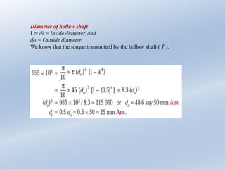
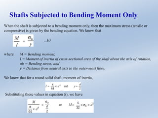
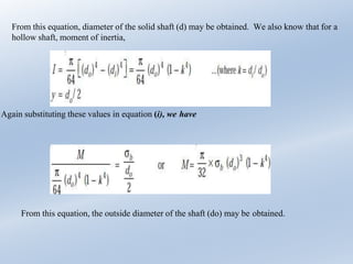
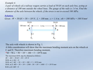
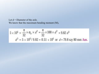

1) The document discusses the design of solid and hollow shafts subjected to torque or bending moments. It provides examples of calculating the diameters of shafts based on the power transmitted, shear stress, bending stress, and other parameters. 2) Formulas are given for calculating the torque capacity and moment of inertia of solid and hollow circular shafts. Examples show how to use the formulas and given values like power, speed, stress limits, and safety factors to determine the necessary shaft diameters. 3) One example calculates the diameter of a railway axle between wheels based on the load on each wheel, distance of the load from the wheel base, gauge of the rails, and not exceeding a bending stress limit. Diagrams


