Downloaded 987 times


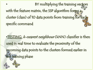
![• TOTAL of 12 samples (3 per sensor)
are recorded in 12-variable vectors
• THE PCA-based feature-extraction
algorithm calculates the eigenvectors and Eigen values
based on the 12-variable vectors
• THREE eigenvectors with the largest
Eigen values are then chosen to set up the feature
matrix [v1, v2, v3]](https://image.slidesharecdn.com/tonguedrivesystembyanu-120922012417-phpapp02/85/Tongue-drive-system-21-320.jpg)
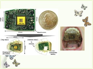
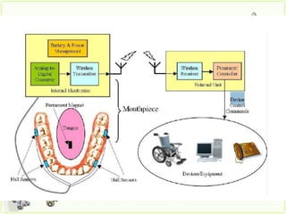
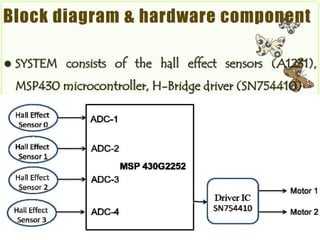
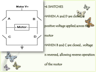


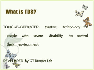
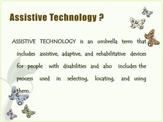
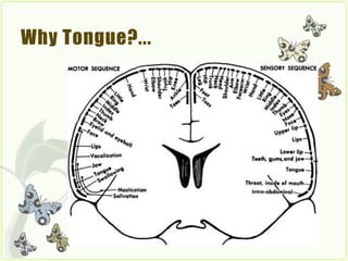
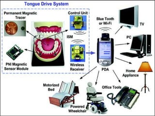
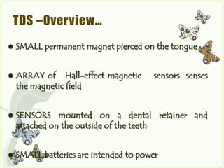
The document describes the Tongue Drive System (TDS), an assistive technology that allows people with severe disabilities to control their environment using only their tongue. [1] TDS uses a small magnet pierced on the tongue and magnetic sensors to detect tongue movements and send wireless signals to control devices like powered wheelchairs. [2] It provides an alternative to existing assistive technologies that have limitations. The document outlines the components, working, advantages and limitations of the TDS.