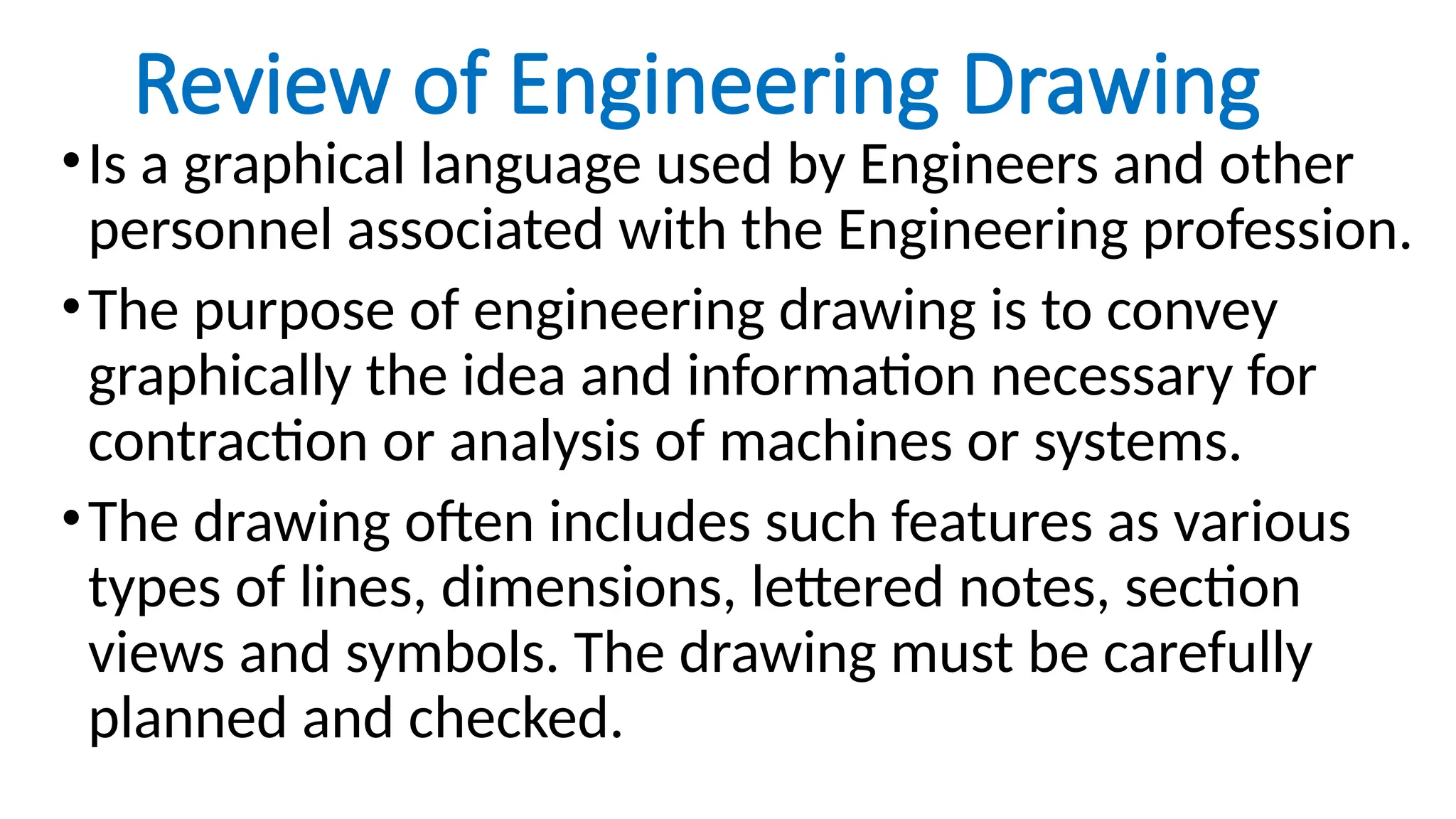
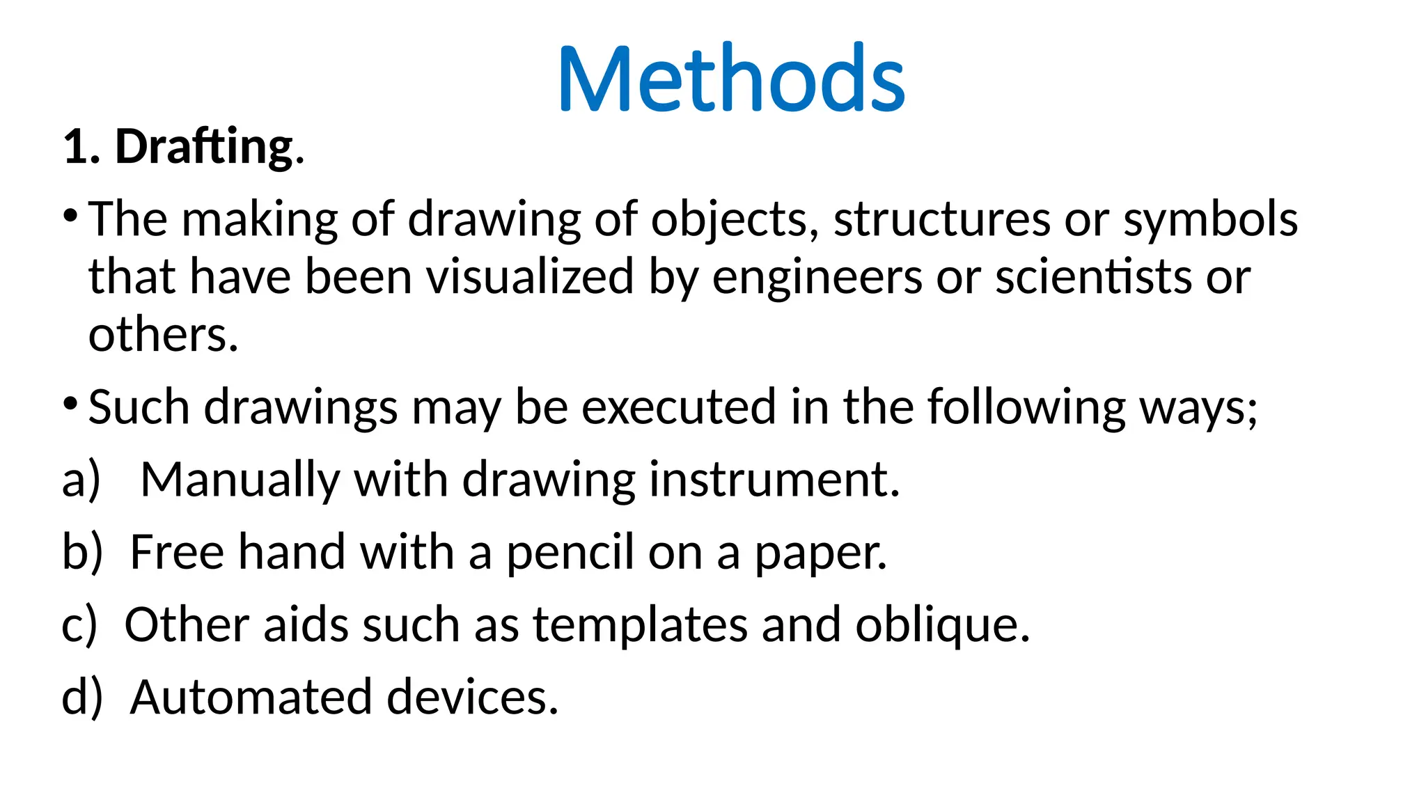
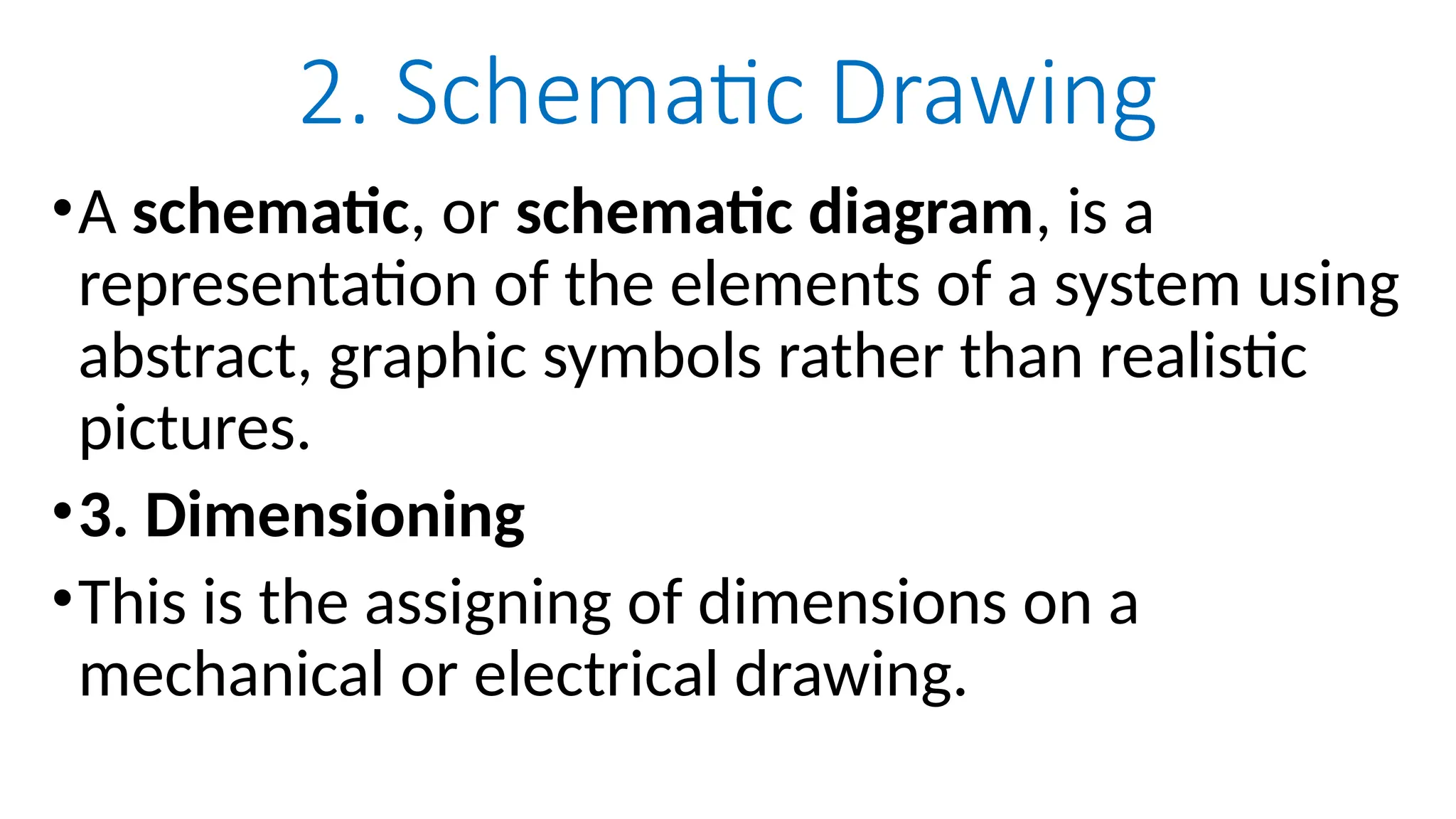
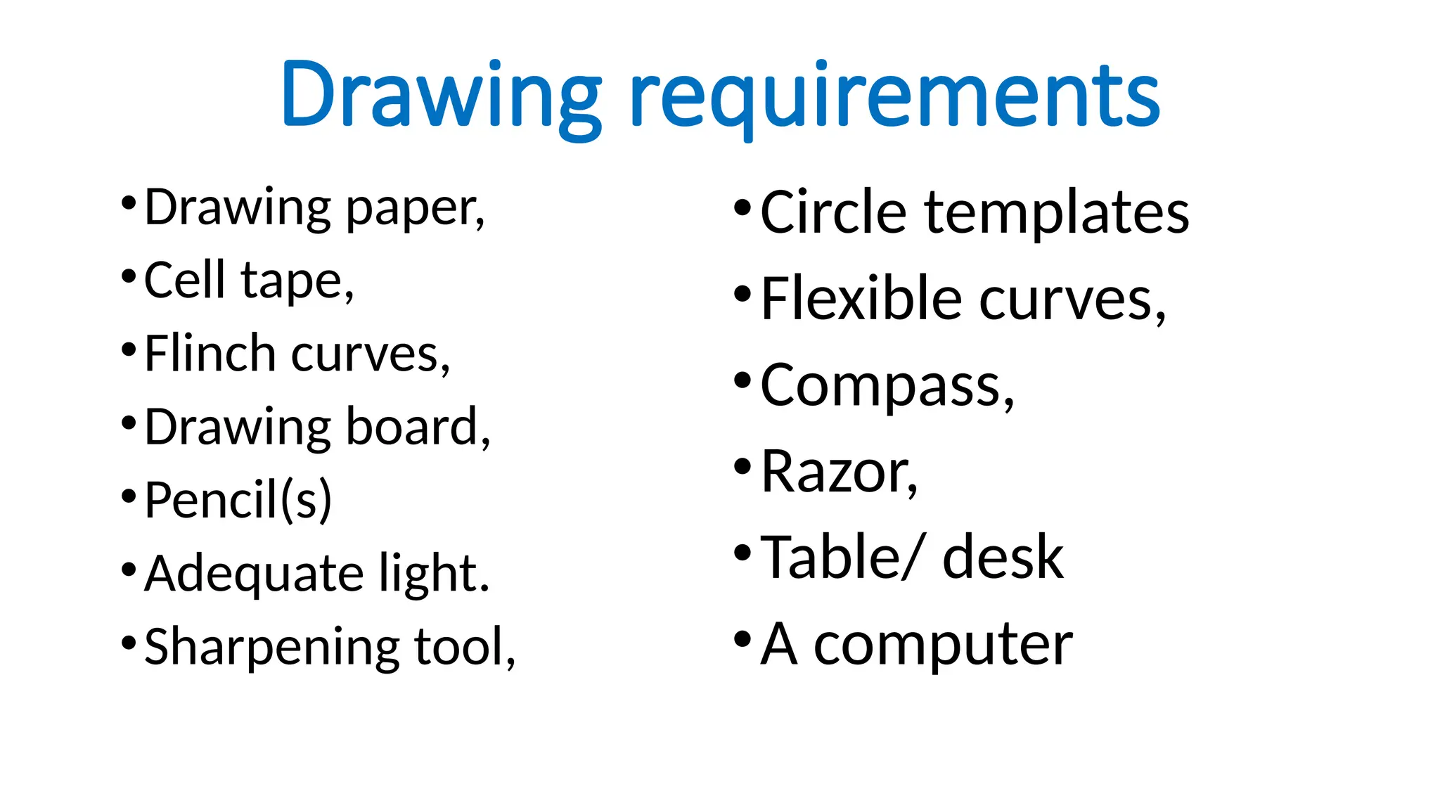
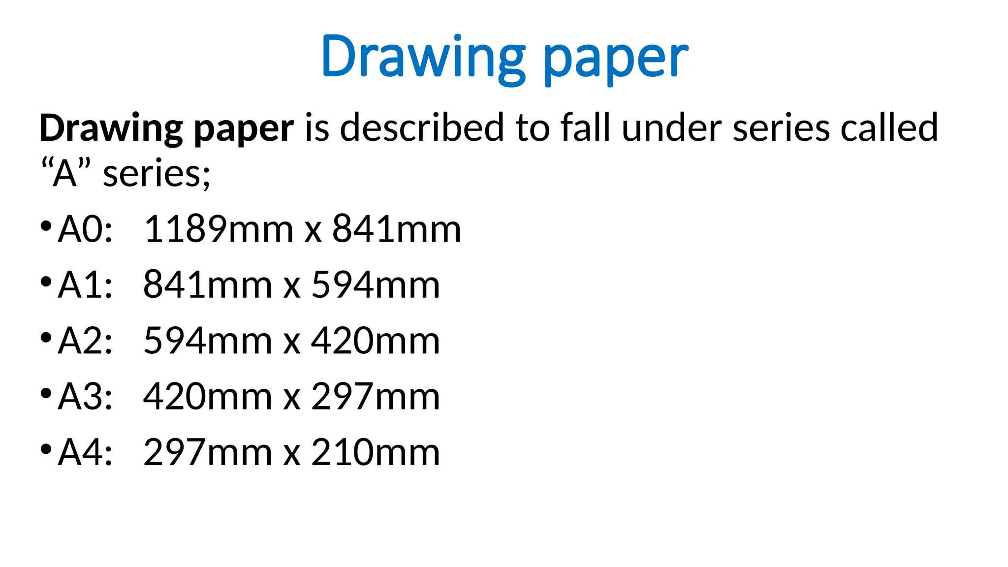
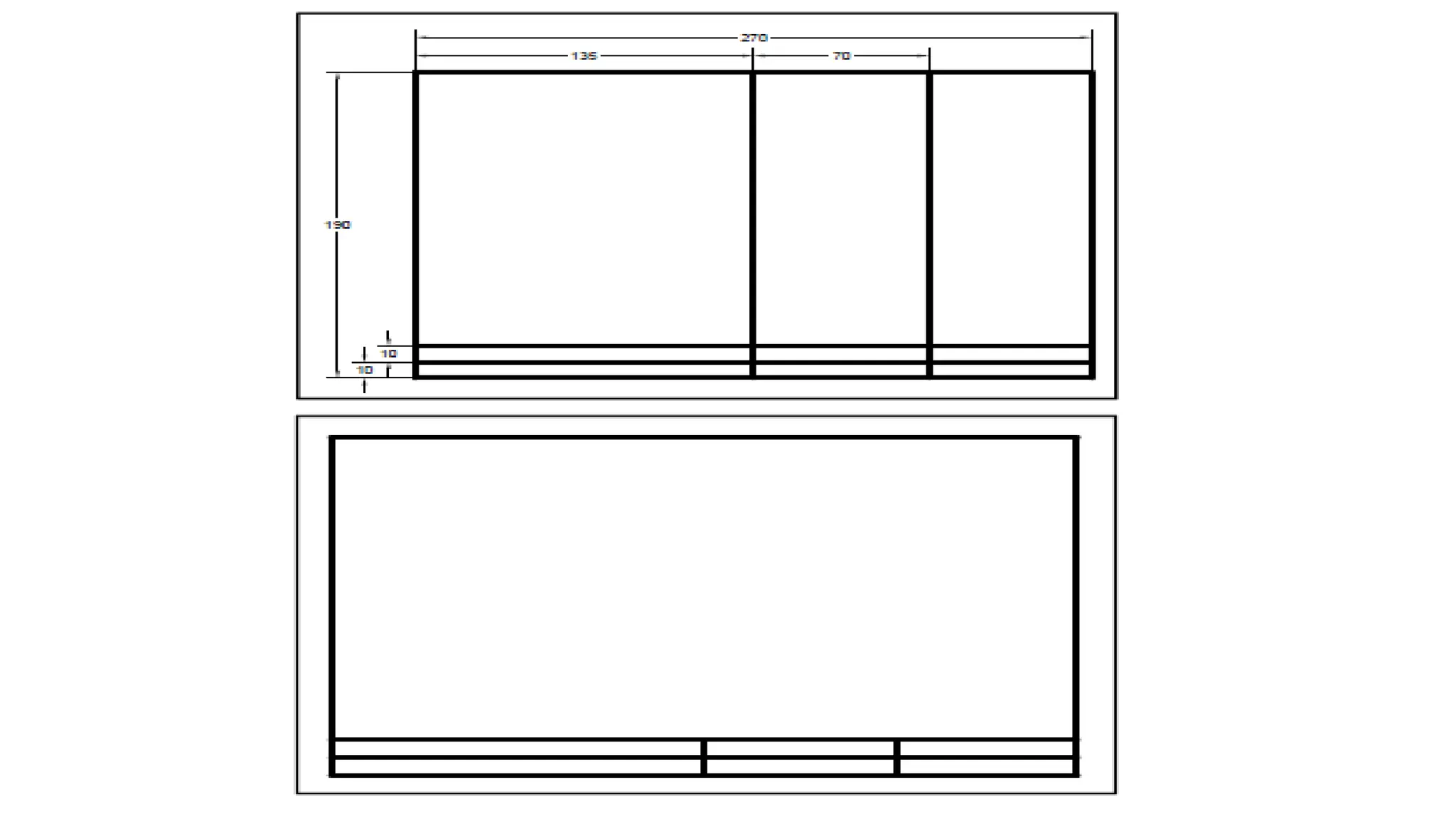
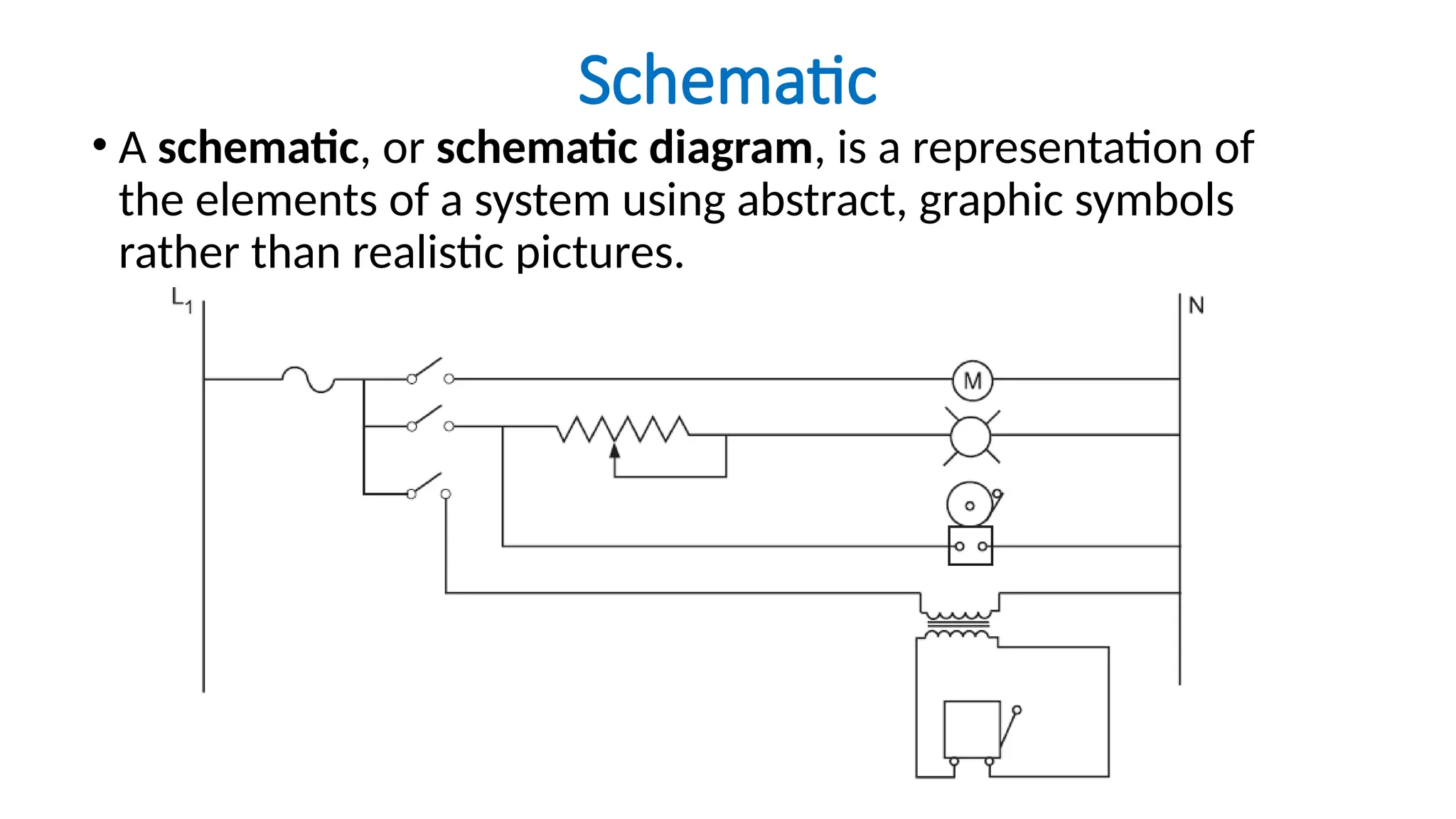
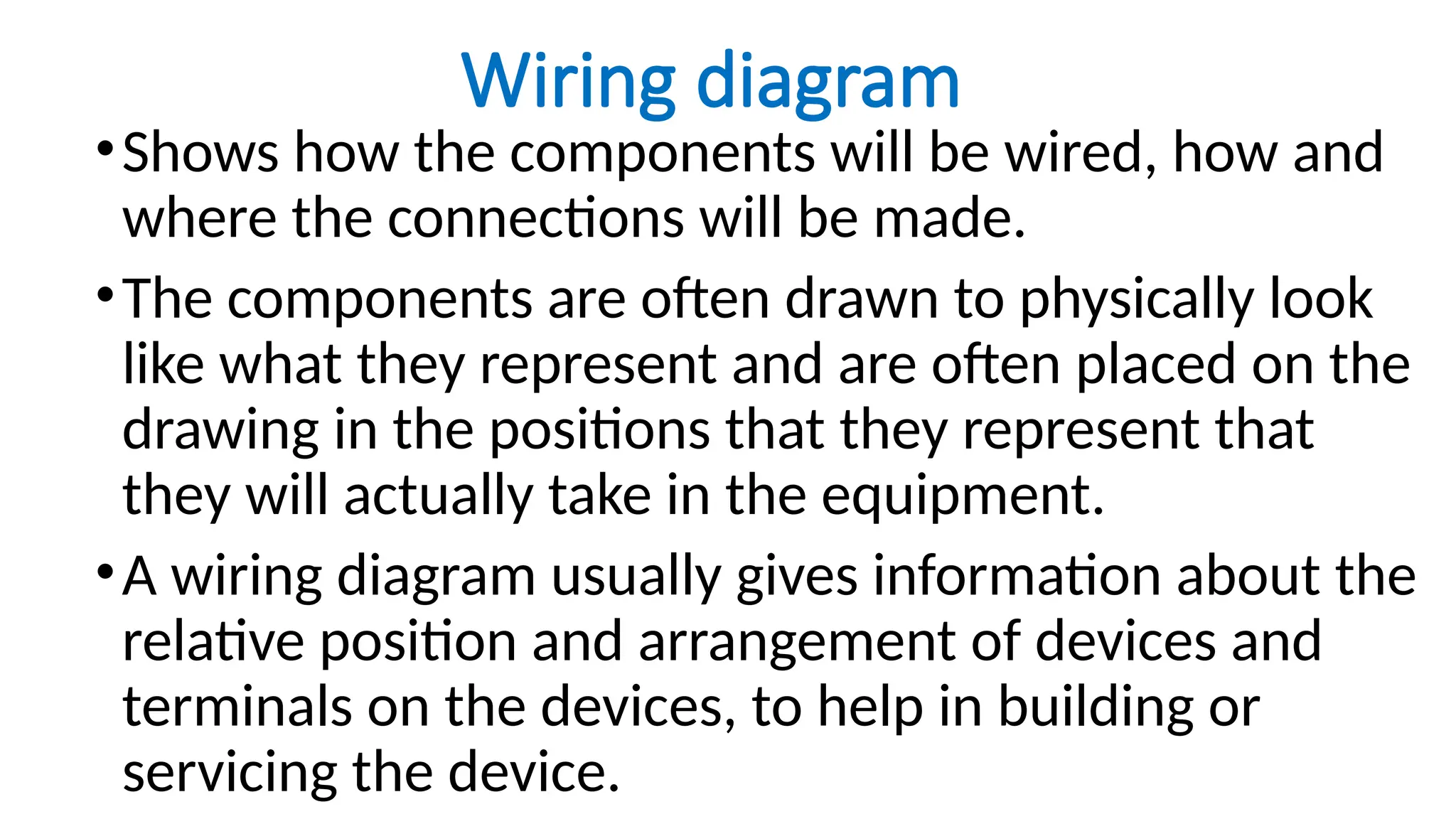
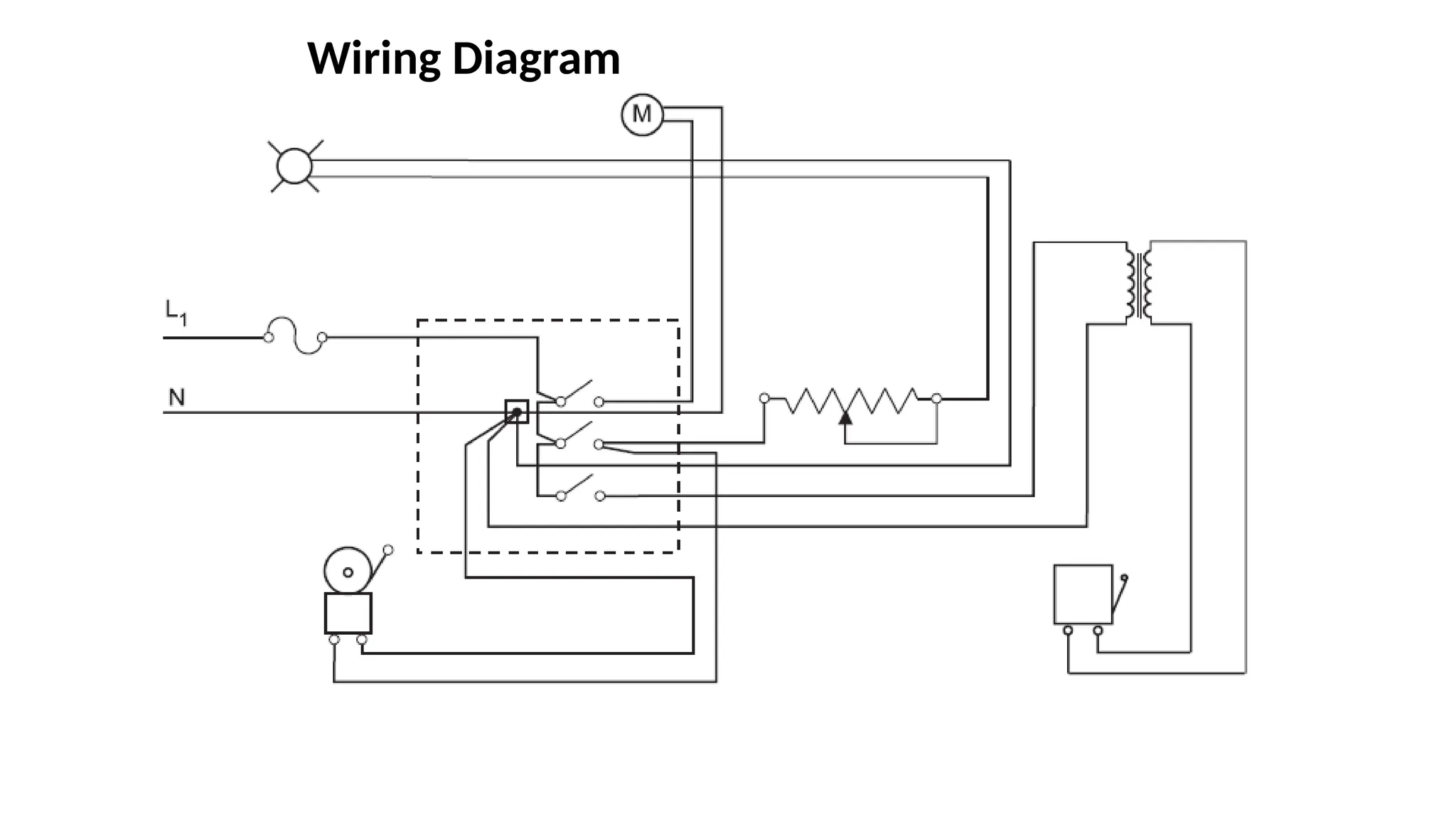
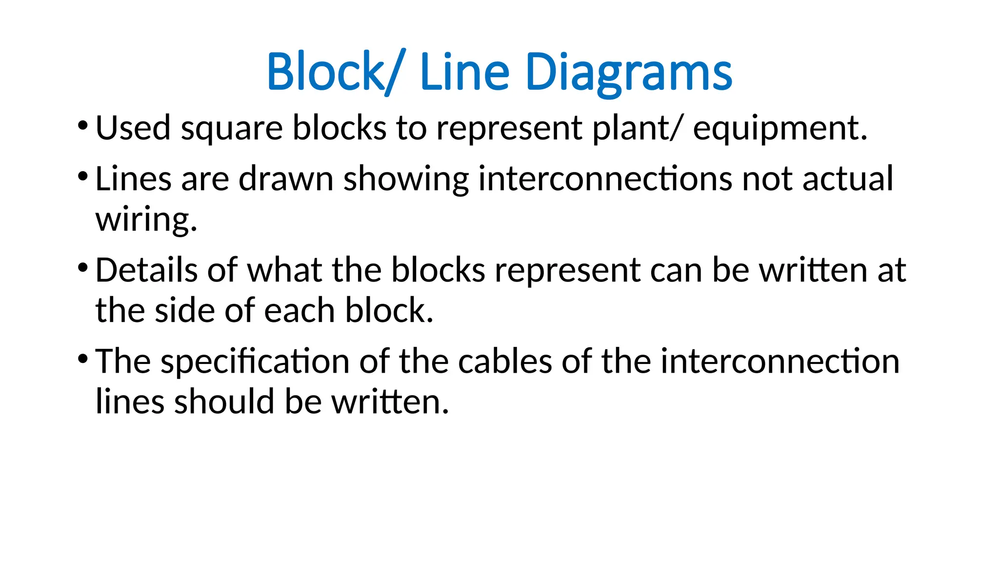
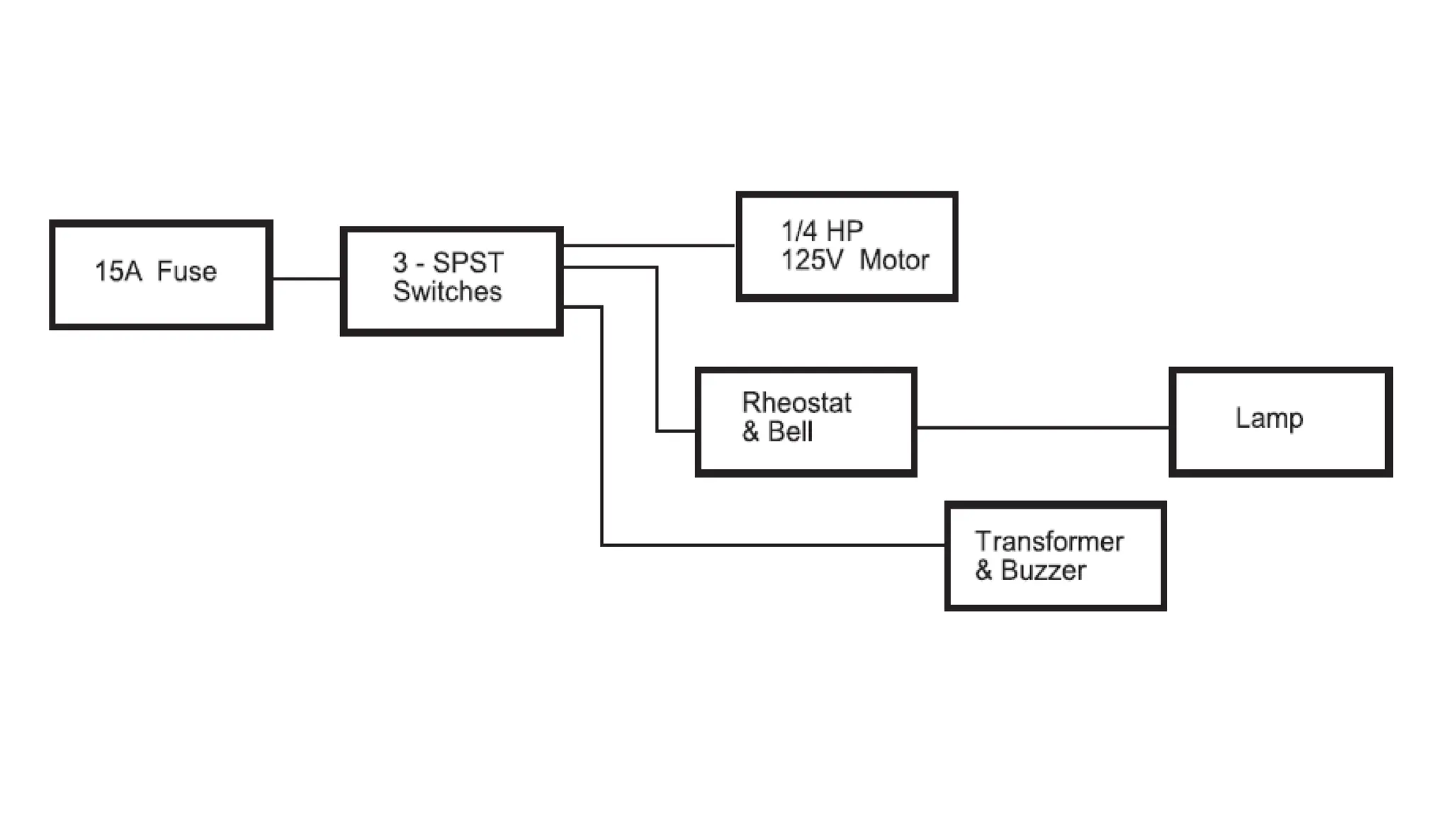
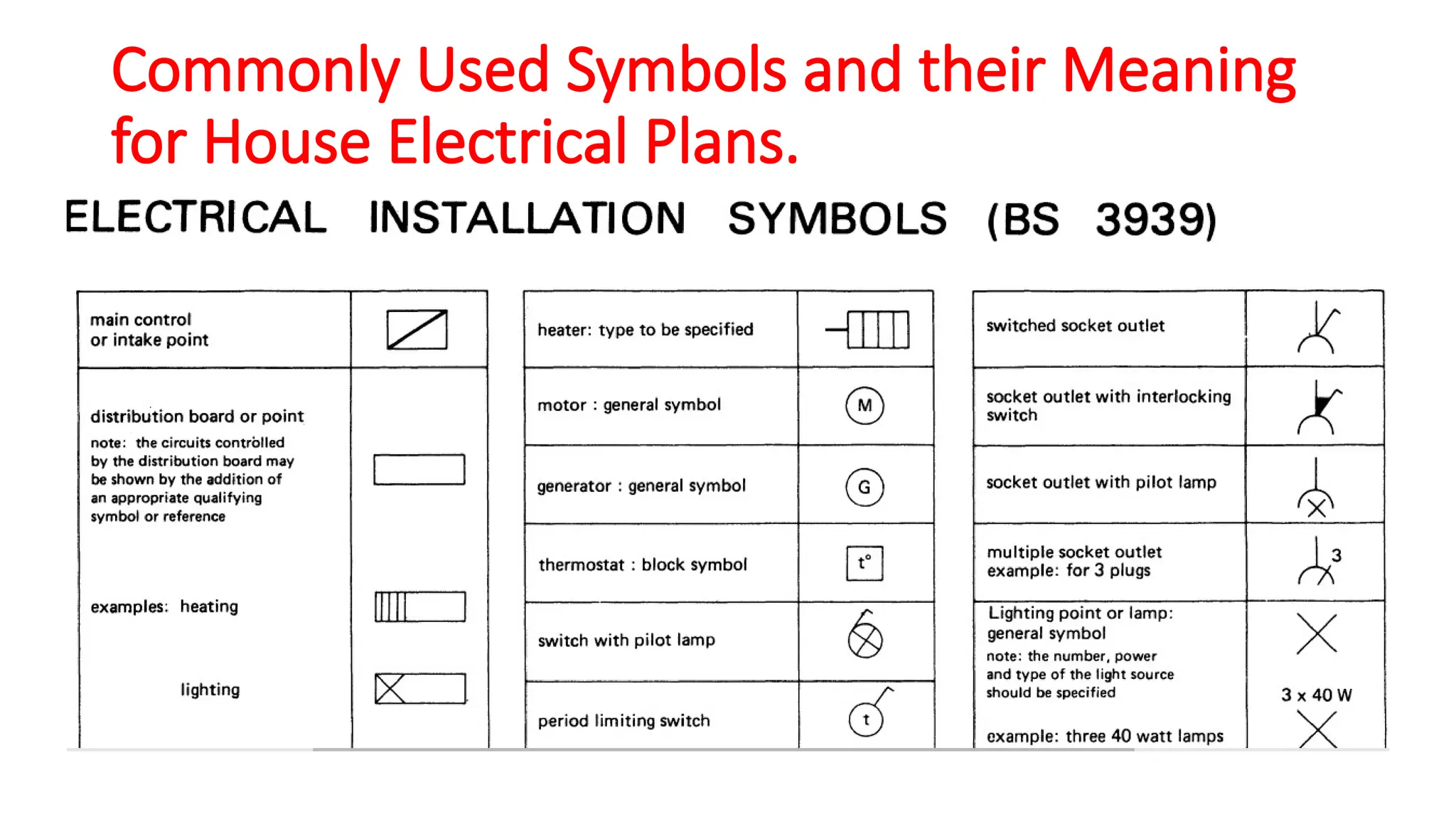
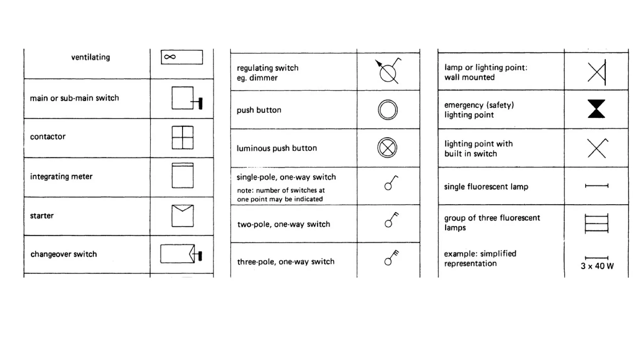
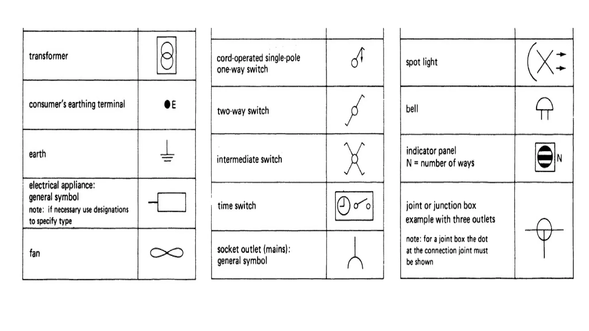
ELECTRICAL ENGINEERING DRAWING
Review of Engineering Drawing
•Is a graphical language used by Engineers and other
personnel associated with the Engineering profession.
•The purpose of engineering drawing is to convey
graphically the idea and information necessary for
contraction or analysis of machines or systems.
•The drawing often includes such features as various
types of lines, dimensions, lettered notes, section
views and symbols. The drawing must be carefully
planned and checked.
Methods
1. Drafting.
•The making of drawing of objects, structures or symbols
that have been visualized by engineers or scientists or
others.
•Such drawings may be executed in the following ways;
a) Manually with drawing instrument.
b) Free hand with a pencil on a paper.
c) Other aids such as templates and oblique.
d) Automated devices.
2. Schematic Drawing
•A schematic, or schematic diagram, is a
representation of the elements of a system using
abstract, graphic symbols rather than realistic
pictures.
•3. Dimensioning
•This is the assigning of dimensions on a
mechanical or electrical drawing.
Drawing requirements
•Drawing paper,
•Cell tape,
•Flinch curves,
•Drawing board,
•Pencil(s)
•Adequate light.
•Sharpening tool,
•Circle templates
•Flexible curves,
•Compass,
•Razor,
•Table/ desk
•A computer
Drawing paper
Drawing paper is described to fall under series called
“A” series;
•A0: 1189mm x 841mm
•A1: 841mm x 594mm
•A2: 594mm x 420mm
•A3: 420mm x 297mm
•A4: 297mm x 210mm
Paper layout
Electrical Engineering Drawing
•Electrical Engineering Drawing is a type of technical drawing
that shows information about power, lighting, and
communication for an Engineering or Architectural project.
•Any electrical working drawing consists of "lines, symbols,
dimensions, and notations to accurately convey
engineering’s design to the workers, who install the
electrical system on the job".
Electrical Engineering Drawing
cont’d…
A complete set of working drawings for the average electrical system in
large projects usually consists of:
1. A plot plan showing the building's location and outside electrical
wiring
2. Floor plans showing the location of electrical systems on every floor
3. Power-riser diagrams showing panel boards
4. Control wiring diagrams
5. Schedules and other information in combination with construction
drawings
How to Draw Electrical Diagrams
Making wiring or electrical diagrams is easy with the
proper templates and symbols:
1. Start with a collection of electrical symbols appropriate
for your diagram
2. Drag and drop symbols to the circuits and connect them
3. Draw circuits represented by lines
4. Use line hops if any lines need to cross
5. Add layers to show complexity
Types of Drawings
Drawings commonly used by the electricians are as
below;
1. Schematic drawing
2. Circuit drawing
3. Block/line drawing
4. Wiring drawing
5. Layout drawing
Line diagram
•A one-line diagram or single-line diagram is a
simplified notation for representing an electrical
system.
Schematic
• A schematic, or schematic diagram, is a representation of
the elements of a system using abstract, graphic symbols
rather than realistic pictures.
Wiring diagram
•Shows how the components will be wired, how and
where the connections will be made.
•The components are often drawn to physically look
like what they represent and are often placed on the
drawing in the positions that they represent that
they will actually take in the equipment.
•A wiring diagram usually gives information about the
relative position and arrangement of devices and
terminals on the devices, to help in building or
servicing the device.
Wiring Diagram
Architectural / Layout Wiring Diagrams
•An architectural or Layout Wiring diagram show shows the
layout of plant and equipment with details of approximate
locations and interconnections of receptacles, lighting, and
permanent electrical services in a building.
•Interconnecting wire routes may be shown approximately,
where particular receptacles or fixtures must be on a
common circuit.
Architectural / Layout Wiring Diagrams
cont’d..
• The electrical symbols not only show where something is to be installed, but
also what type of device is being installed.
• For example, a surface ceiling light is shown by one symbol, a recessed ceiling
light has a different symbol, and a surface fluorescent light has another symbol.
• Each type of switch has a different symbol and so do the various outlets. There
are symbols that show the location of smoke detectors, the doorbell chime, and
thermostat.
• On large projects symbols may be numbered to show, for example, the panel
board and circuit to which the device connects, and also to identify which of
several types of fixture are to be installed at that location.
• A set of wiring diagrams may be required by the electrical inspection authority
to approve connection of the residence to the public electrical supply system.
Circuit Diagrams
•They show clearly the way that components are
connected for a given equipment using BS 3939
symbols.
•The layout and interconnections bear no relation to
the way that this will actually be on the equipment.
Block/ Line Diagrams
•Used square blocks to represent plant/ equipment.
•Lines are drawn showing interconnections not actual
wiring.
•Details of what the blocks represent can be written at
the side of each block.
•The specification of the cables of the interconnection
lines should be written.
The Importance of Electrical Engineering
Drawing to the Electro-Technical Industry
1. Used in the design of Electrical and Electronic systems.
2. Helps in the location of faults for repair and maintenance
work.
3. Helps in installation work to determine the exact locations of
different components and accessories.
4. Enables the Engineer to make modifications at a later time
basing on the previous designs.
5. Used to estimate the cost/make Bills of Quantities of a
project.
Commonly Used Symbols and their Meaning
for House Electrical Plans.
An introduction to electrical engineeering drawing.pptx

An introduction to electrical engineeering drawing.pptx

  • 1.
  • 2.
    Review of EngineeringDrawing •Is a graphical language used by Engineers and other personnel associated with the Engineering profession. •The purpose of engineering drawing is to convey graphically the idea and information necessary for contraction or analysis of machines or systems. •The drawing often includes such features as various types of lines, dimensions, lettered notes, section views and symbols. The drawing must be carefully planned and checked.
  • 3.
    Methods 1. Drafting. •The makingof drawing of objects, structures or symbols that have been visualized by engineers or scientists or others. •Such drawings may be executed in the following ways; a) Manually with drawing instrument. b) Free hand with a pencil on a paper. c) Other aids such as templates and oblique. d) Automated devices.
  • 4.
    2. Schematic Drawing •Aschematic, or schematic diagram, is a representation of the elements of a system using abstract, graphic symbols rather than realistic pictures. •3. Dimensioning •This is the assigning of dimensions on a mechanical or electrical drawing.
  • 5.
    Drawing requirements •Drawing paper, •Celltape, •Flinch curves, •Drawing board, •Pencil(s) •Adequate light. •Sharpening tool, •Circle templates •Flexible curves, •Compass, •Razor, •Table/ desk •A computer
  • 6.
    Drawing paper Drawing paperis described to fall under series called “A” series; •A0: 1189mm x 841mm •A1: 841mm x 594mm •A2: 594mm x 420mm •A3: 420mm x 297mm •A4: 297mm x 210mm
  • 7.
  • 9.
    Electrical Engineering Drawing •ElectricalEngineering Drawing is a type of technical drawing that shows information about power, lighting, and communication for an Engineering or Architectural project. •Any electrical working drawing consists of "lines, symbols, dimensions, and notations to accurately convey engineering’s design to the workers, who install the electrical system on the job".
  • 10.
    Electrical Engineering Drawing cont’d… Acomplete set of working drawings for the average electrical system in large projects usually consists of: 1. A plot plan showing the building's location and outside electrical wiring 2. Floor plans showing the location of electrical systems on every floor 3. Power-riser diagrams showing panel boards 4. Control wiring diagrams 5. Schedules and other information in combination with construction drawings
  • 11.
    How to DrawElectrical Diagrams Making wiring or electrical diagrams is easy with the proper templates and symbols: 1. Start with a collection of electrical symbols appropriate for your diagram 2. Drag and drop symbols to the circuits and connect them 3. Draw circuits represented by lines 4. Use line hops if any lines need to cross 5. Add layers to show complexity
  • 12.
    Types of Drawings Drawingscommonly used by the electricians are as below; 1. Schematic drawing 2. Circuit drawing 3. Block/line drawing 4. Wiring drawing 5. Layout drawing
  • 13.
    Line diagram •A one-linediagram or single-line diagram is a simplified notation for representing an electrical system.
  • 14.
    Schematic • A schematic,or schematic diagram, is a representation of the elements of a system using abstract, graphic symbols rather than realistic pictures.
  • 15.
    Wiring diagram •Shows howthe components will be wired, how and where the connections will be made. •The components are often drawn to physically look like what they represent and are often placed on the drawing in the positions that they represent that they will actually take in the equipment. •A wiring diagram usually gives information about the relative position and arrangement of devices and terminals on the devices, to help in building or servicing the device.
  • 16.
  • 17.
    Architectural / LayoutWiring Diagrams •An architectural or Layout Wiring diagram show shows the layout of plant and equipment with details of approximate locations and interconnections of receptacles, lighting, and permanent electrical services in a building. •Interconnecting wire routes may be shown approximately, where particular receptacles or fixtures must be on a common circuit.
  • 18.
    Architectural / LayoutWiring Diagrams cont’d.. • The electrical symbols not only show where something is to be installed, but also what type of device is being installed. • For example, a surface ceiling light is shown by one symbol, a recessed ceiling light has a different symbol, and a surface fluorescent light has another symbol. • Each type of switch has a different symbol and so do the various outlets. There are symbols that show the location of smoke detectors, the doorbell chime, and thermostat. • On large projects symbols may be numbered to show, for example, the panel board and circuit to which the device connects, and also to identify which of several types of fixture are to be installed at that location. • A set of wiring diagrams may be required by the electrical inspection authority to approve connection of the residence to the public electrical supply system.
  • 20.
    Circuit Diagrams •They showclearly the way that components are connected for a given equipment using BS 3939 symbols. •The layout and interconnections bear no relation to the way that this will actually be on the equipment.
  • 22.
    Block/ Line Diagrams •Usedsquare blocks to represent plant/ equipment. •Lines are drawn showing interconnections not actual wiring. •Details of what the blocks represent can be written at the side of each block. •The specification of the cables of the interconnection lines should be written.
  • 24.
    The Importance ofElectrical Engineering Drawing to the Electro-Technical Industry 1. Used in the design of Electrical and Electronic systems. 2. Helps in the location of faults for repair and maintenance work. 3. Helps in installation work to determine the exact locations of different components and accessories. 4. Enables the Engineer to make modifications at a later time basing on the previous designs. 5. Used to estimate the cost/make Bills of Quantities of a project.
  • 25.
    Commonly Used Symbolsand their Meaning for House Electrical Plans.