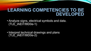
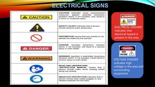
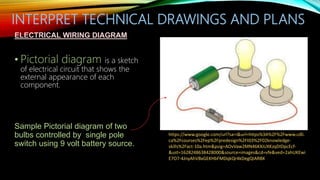
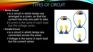
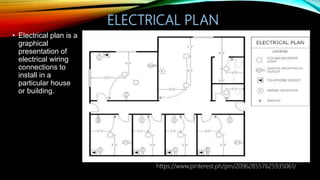
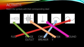
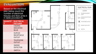
TLE 7/8-ELECTRICAL
INSTALLATION AND
MAINTENANCE
ANALYZE SIGNS, SYMBOLS AND DATA
Prepared by:
JOANNA MAE M. DAVID
LEARNING COMPETENCIES TO BE
DEVELOPED
• Analyze signs, electrical symbols and data.
(TLE_IAEI7/8ID0e-1)
• Interpret technical drawings and plans
(TLE_IAEI7/8ID0e-2)
WHAT ARE ELECTRICAL SYMBOLS?
• Electrical Symbols are small drawings or pictograms used
to represent various electrical devices in a diagram or
plan of an electrical circuit.
• These symbols are used in sketching schematic diagrams
and electrical plans for numerous types of electrical
works.
ELECTRICAL SYMBOLS
ELECTRICAL SIGNS
ELECTRICAL HAZARD
indicates that
electrical hazard is
present in the area.
VOLTAGE DANGER
indicates high
voltage in the area and
surrounding
equipment.
INTERPRET TECHNICAL DRAWINGS AND PLANS
ELECTRICAL WIRING DIAGRAM
• Pictorial diagram is a sketch
of electrical circuit that shows the
external appearance of each
component.
Sample Pictorial diagram of two
bulbs controlled by single pole
switch using 9 volt battery source.
https://www.google.com/url?sa=i&url=https%3A%2F%2Fwww.cdli.
ca%2Fcourses%2Fep%2Fpredesign%2Ft03%2F02knowledge-
skills%2Fact-10a.htm&psig=AOvVaw2MN46KXiUXKzqDIDpcEcf-
&ust=1628248638428000&source=images&cd=vfe&ved=2ahUKEwi
E7O7-4JnyAhVBxGEKHbFMDqkQr4kDegQIARBX
INTERPRET TECHNICAL DRAWINGS AND PLANS
ELECTRICAL WIRING DIAGRAM
Schematic diagram is a sketch showing the components of the circuit using
standard electrical symbols.
It shows the actual number of components and how the wiring is routed but not the
actual location.
TYPES OF CIRCUIT
• Series Circuit
is a circuit in which lamps are
arranged in a chain, so that the
current has only one path to take.
Current is the same in each load
but the voltage varies.
• Parallel Circuit
is a circuit in which lamps are
connected across the wires.
Voltage is the same in each load
but the current varies
ELECTRICAL PLAN
• Electrical plan is a
graphical
presentation of
electrical wiring
connections to
install in a
particular house
or building.
https://www.pinterest.ph/pin/209628557625935061/
ACTIVITY:
Match the symbols with their corresponding label
FUSE RANGE
OUTLET
CIRCUIT
BREAKER
BATTER
Y
GROUND
Based on the electrical
plan below count the
number of electrical
fixtures and then write it
in table provided for.
QUANTIT
Y
ELECTRICAL
FIXTURES
CEILING
MOUNTED
BULB
DUPLEX
RECEPTACLE
OUTLET
TELEPHONE
OUTLET
SMOKE
DETECTOR
SWITCH
EVALUATION
ASSIGNMENT
• Write a reflection about the importance of understanding electrical signs, symbols
and plans. Use at least 5 sentences for your essay.
• Rubrics
Used 5 or more
than 5 sentences
Used 4 sentences Used 3 sentences Used 2 sentences Used only 1
sentence
5 4 3 2 1
Thank you!

TLE7 EIM Week 4 3rd Q analyzing symbols and data.pptx

  • 1.
    TLE 7/8-ELECTRICAL INSTALLATION AND MAINTENANCE ANALYZESIGNS, SYMBOLS AND DATA Prepared by: JOANNA MAE M. DAVID
  • 2.
    LEARNING COMPETENCIES TOBE DEVELOPED • Analyze signs, electrical symbols and data. (TLE_IAEI7/8ID0e-1) • Interpret technical drawings and plans (TLE_IAEI7/8ID0e-2)
  • 3.
    WHAT ARE ELECTRICALSYMBOLS? • Electrical Symbols are small drawings or pictograms used to represent various electrical devices in a diagram or plan of an electrical circuit. • These symbols are used in sketching schematic diagrams and electrical plans for numerous types of electrical works.
  • 4.
  • 5.
    ELECTRICAL SIGNS ELECTRICAL HAZARD indicatesthat electrical hazard is present in the area. VOLTAGE DANGER indicates high voltage in the area and surrounding equipment.
  • 6.
    INTERPRET TECHNICAL DRAWINGSAND PLANS ELECTRICAL WIRING DIAGRAM • Pictorial diagram is a sketch of electrical circuit that shows the external appearance of each component. Sample Pictorial diagram of two bulbs controlled by single pole switch using 9 volt battery source. https://www.google.com/url?sa=i&url=https%3A%2F%2Fwww.cdli. ca%2Fcourses%2Fep%2Fpredesign%2Ft03%2F02knowledge- skills%2Fact-10a.htm&psig=AOvVaw2MN46KXiUXKzqDIDpcEcf- &ust=1628248638428000&source=images&cd=vfe&ved=2ahUKEwi E7O7-4JnyAhVBxGEKHbFMDqkQr4kDegQIARBX
  • 7.
    INTERPRET TECHNICAL DRAWINGSAND PLANS ELECTRICAL WIRING DIAGRAM Schematic diagram is a sketch showing the components of the circuit using standard electrical symbols. It shows the actual number of components and how the wiring is routed but not the actual location.
  • 8.
    TYPES OF CIRCUIT •Series Circuit is a circuit in which lamps are arranged in a chain, so that the current has only one path to take. Current is the same in each load but the voltage varies. • Parallel Circuit is a circuit in which lamps are connected across the wires. Voltage is the same in each load but the current varies
  • 9.
    ELECTRICAL PLAN • Electricalplan is a graphical presentation of electrical wiring connections to install in a particular house or building. https://www.pinterest.ph/pin/209628557625935061/
  • 10.
    ACTIVITY: Match the symbolswith their corresponding label FUSE RANGE OUTLET CIRCUIT BREAKER BATTER Y GROUND
  • 11.
    Based on theelectrical plan below count the number of electrical fixtures and then write it in table provided for. QUANTIT Y ELECTRICAL FIXTURES CEILING MOUNTED BULB DUPLEX RECEPTACLE OUTLET TELEPHONE OUTLET SMOKE DETECTOR SWITCH EVALUATION
  • 12.
    ASSIGNMENT • Write areflection about the importance of understanding electrical signs, symbols and plans. Use at least 5 sentences for your essay. • Rubrics Used 5 or more than 5 sentences Used 4 sentences Used 3 sentences Used 2 sentences Used only 1 sentence 5 4 3 2 1
  • 13.

Editor's Notes

  • #4 Practically any electrical fixture found in a house has a symbol that coincides to said fixture on an electrical wiring diagram. These are very useful guide for an electrician or electrical contractor, thus, making the wiring easier to install as well
  • #5 The following are common electrical symbols used in sketching wiring plan and diagram.
  • #7 The flow of current in a conductor or wire can be represented by diagram. There are two types of diagram: pictorial diagram and schematic diagram It is much like a photograph of the circuit and uses simple images of parts.
  • #10 It indicates the position of electrical fixtures such as convenience outlets, switches, lightings, door bells, and others to be installed.