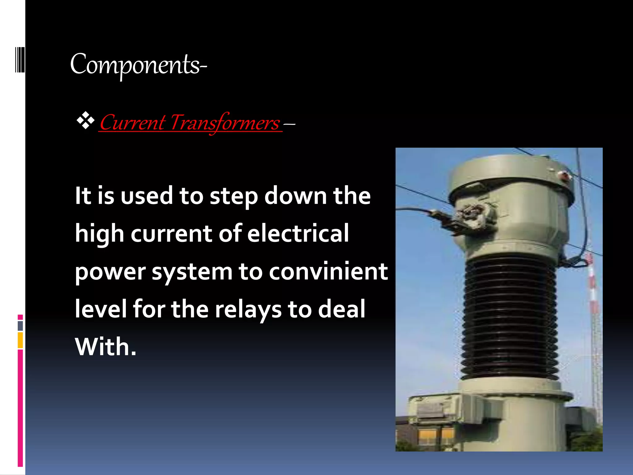
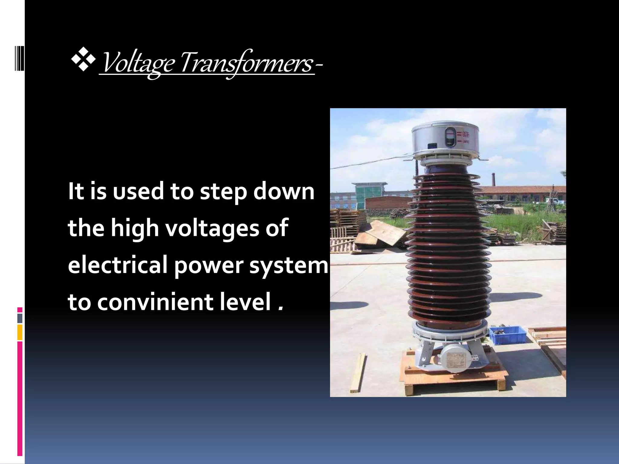
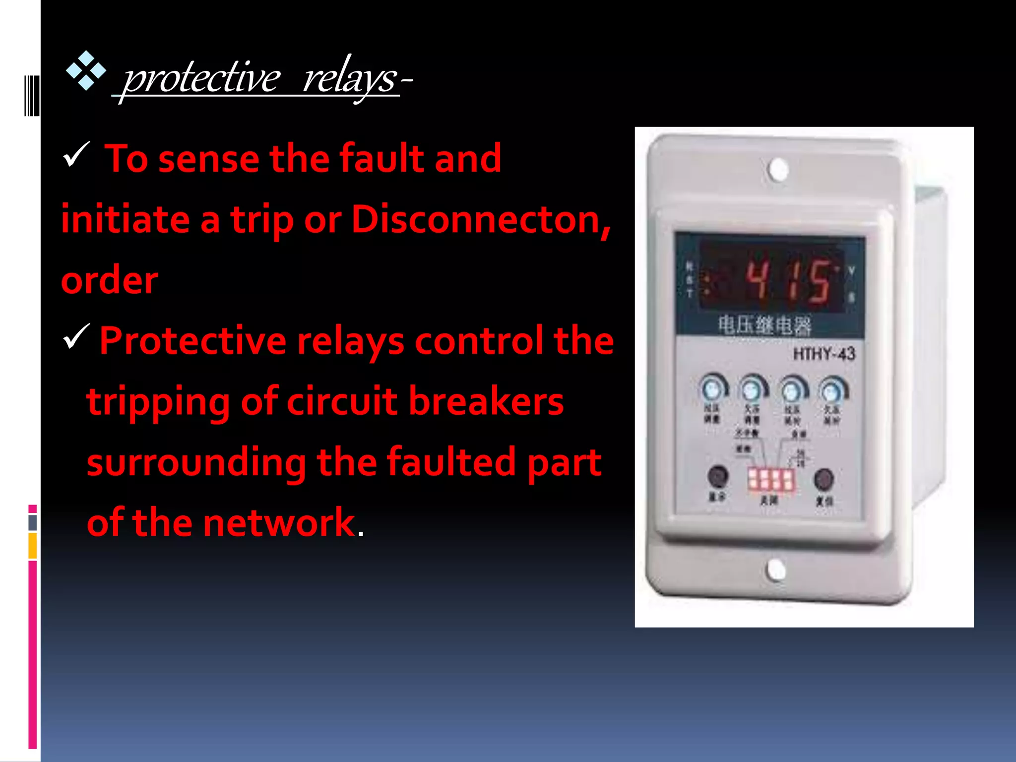
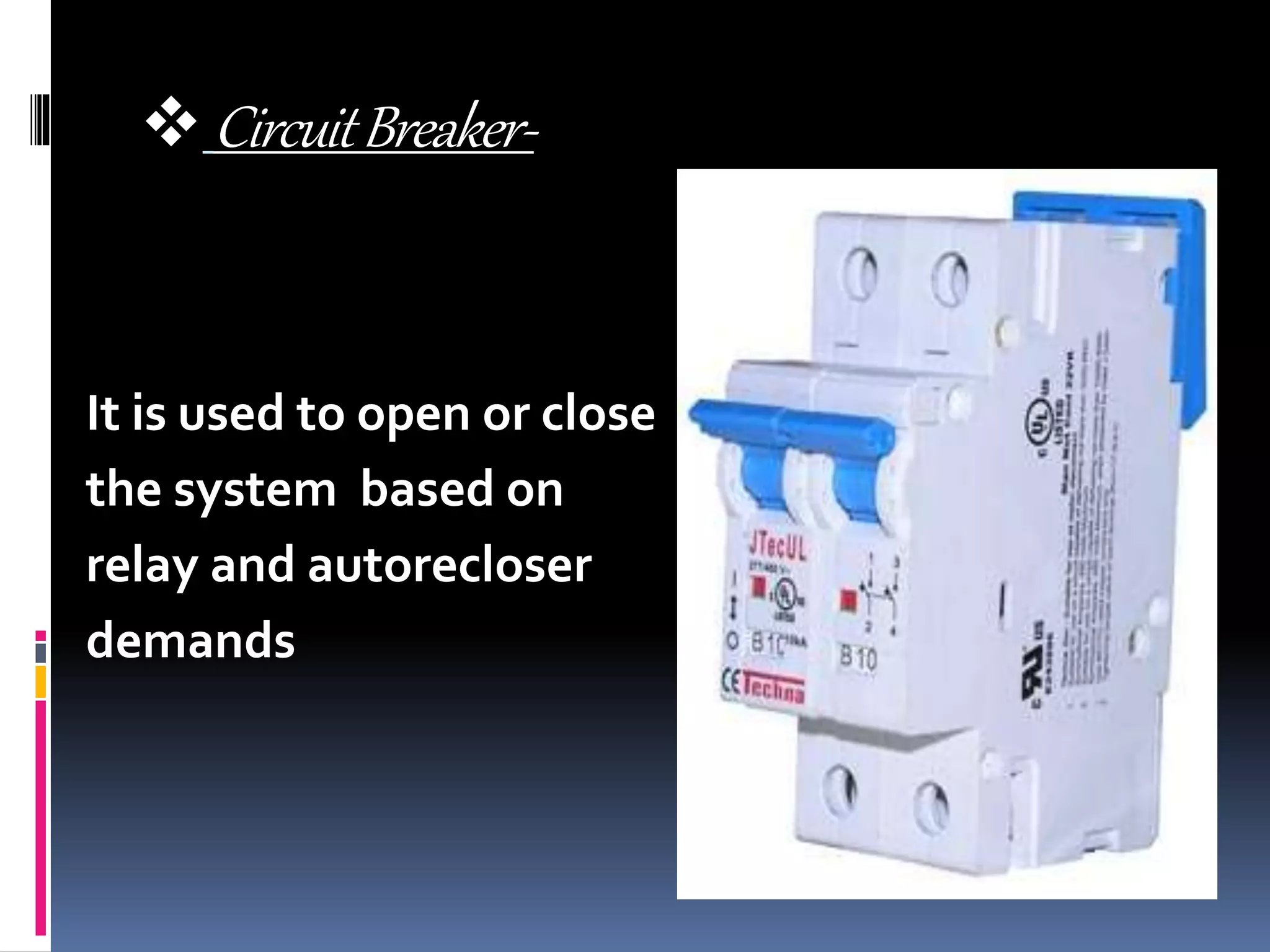
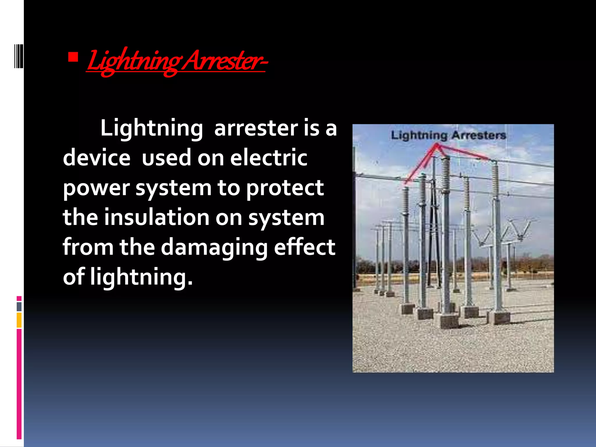
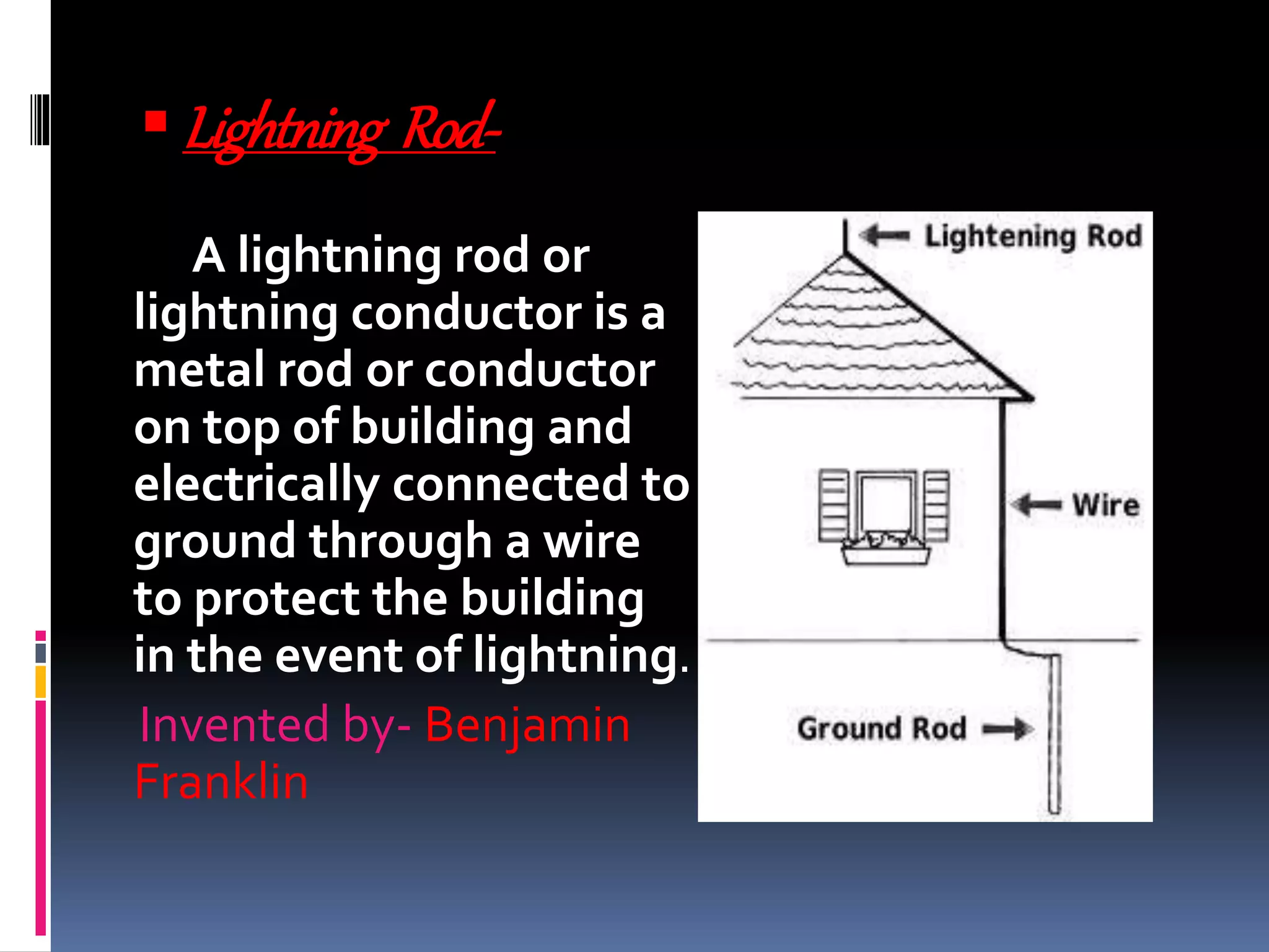
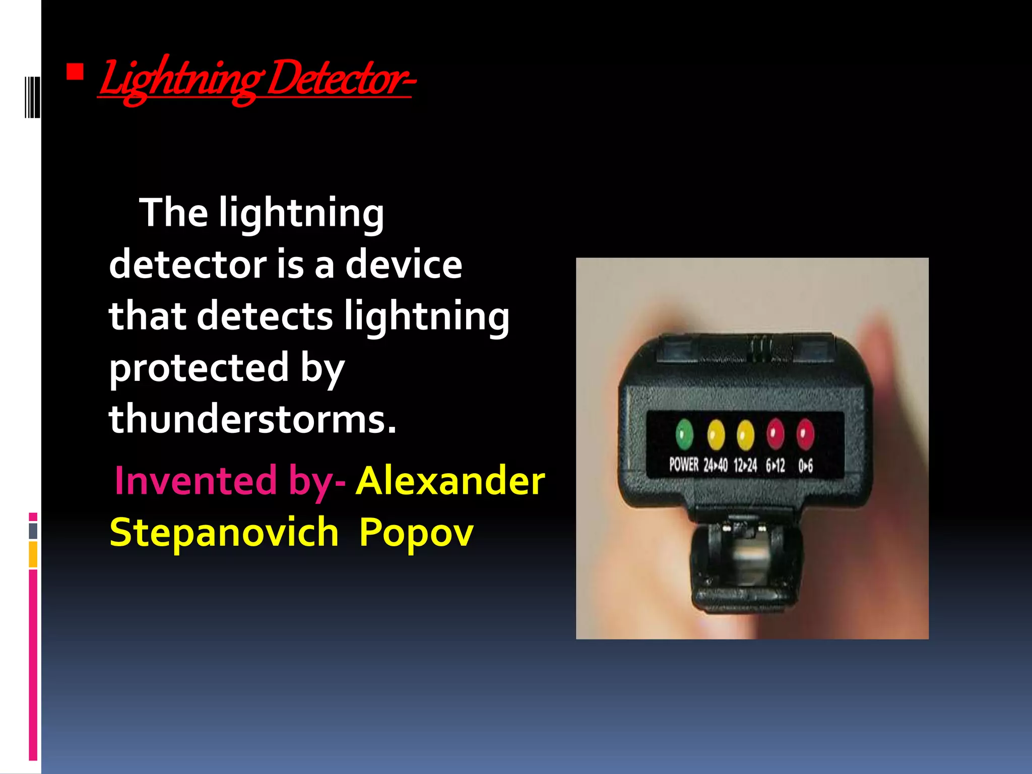
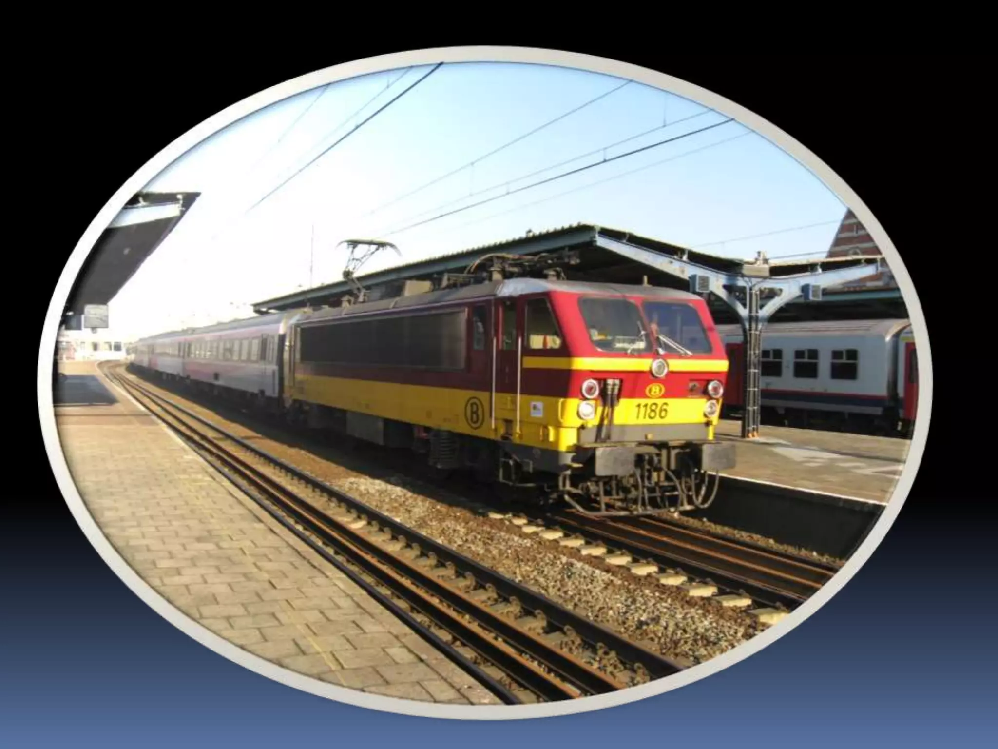
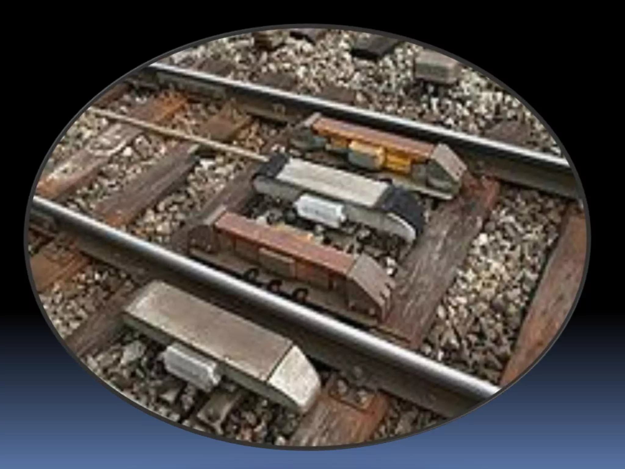
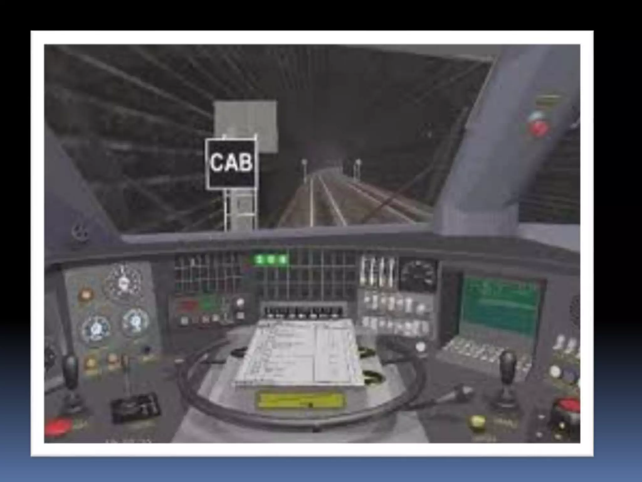
Presentation on-
The Protection System
by
shridharkulkarni
OUTLINES-
 Power System Protection
 Lightning Protection System
 Train Protection System
 Power Protection System
 Defination
 Objectives
 Protection
 Components
 Co-ordination
Defination-
Power system protection is the
branch of electrical power engineering that
deals with the protection of electrical power
system from fault.
Objectives-
1) To determine rating and setting of
fuses, circuit breakers , relays etc.
2) To isolate fault or overload
Protection-
 Prevent injury to personnel
 Minimize damage to component
 Quickly isolate the affected portion of the system
 Minimize the magnitude of available short circuit
Components-
Current Transformers –
It is used to step down the
high current of electrical
power system to convinient
level for the relays to deal
With.
VoltageTransformers-
It is used to step down
the high voltages of
electrical power system
to convinient level .
 protective relays-
 To sense the fault and
initiate a trip or Disconnecton,
order
 Protective relays control the
tripping of circuit breakers
surrounding the faulted part
of the network.
 CircuitBreaker-
It is used to open or close
the system based on
relay and autorecloser
demands
 Batteries -
.
It is used to provide
Power in the case of
Power disconnection
In the system
Co-ordination
Protective device coordination is
the process of determining the “ best fit “
timing of current interruption when
abnormal conditions occur.The goal is to
minimize an outage to the greatest extent
possible. Historically, protective device
coordination was done on translucent log-
log paper.
Lightning protection system
 Defination
 Description
 Lightning Devices
 Risk Assessment
Defination-
A lightning protection system is
a system designed to protect a structure
from damage due to lightning strikes by
intercepting such strikes and safety passing
their extremely high voltage current to
ground.
Description-
Lightning protection system are used
to prevent or lesson damage to structures
done by lightning strikes. Lightning
protection system mitigate the fire hazard
which lightning strike pose to structure. A
lightning protection system provides low
impedence path for the lightning current to
lesson the heating effect of current flowing
through flammable structural material.
-
Because of high energy and current
level associated with lightning (currents can
be in excess of 150,000 A) and the very
rapid rise time of lightning strike, no
lightning protection system can guarantee
absolute safety from lightning.
Lightning devices-
 Lightning Arrester
 Lightning Rod
 Lightning Detector
LightningArrester-
Lightning arrester is a
device used on electric
power system to protect
the insulation on system
from the damaging effect
of lightning.
-
Metal OxideVariastor (MOVs) have
been used for power system protection
since mid 1970’s.The typical lightning
arrester also known as surge arrester has
a high voltage terminal and a ground
terminal.
when lightning surge or switching
surge travels down the power system to
arrester, the current from the surge is
diverted around the protected insulation
in most cases to earth.
Lightning Rod-
A lightning rod or
lightning conductor is a
metal rod or conductor
on top of building and
electrically connected to
ground through a wire
to protect the building
in the event of lightning.
Invented by- Benjamin
Franklin
LightningDetector-
The lightning
detector is a device
that detects lightning
protected by
thunderstorms.
Invented by- Alexander
Stepanovich Popov
RiskAssessment
Some structures are inherently
more or less at risk of being struck by
lightning.The risk for structure is function
of size of structure, the height, and number
of lightning strike s per year per mi square.
 Train Protection System
 Defination
 Inductive system and Integra signum
system
 cab signalling
 Future
Defination-
A train protection system is a railway
technical installation to ensure safe
operation in the event of human failure.
Inductive and Integra signumsystem
In this system data is transmitted
magnetically between the track and
locomotive by magnets mounted beside the
rails and on the locomotive.
Integra Signum was a publicly-traded
Swiss company active in train control and
signaling systems. Its main achievement was
the development of the train control system. It
was subsequently adopted by the Swiss
Federal Railways in 1933.
-
In the Integra – Signum system the trains
are influenced only at given locations , for
instance whenever a train ignores a red signal ,
the emergency brakes are applied and the
locomotive's motors are shut down.
This gives sufficient braking distance for
trains following each other , however it cannot
always prevent accidents in stations where
trains cross paths , because the distance from
the red signal to the next obstacle may be too
short for the train to brake to a halt.
CabSignalling-
The newest systems use cab signalling ,
where the trains constantly receive information
regarding their relative positions to other
trains.The computer shows the driver how fast
he may drive, instead of him relying on
exterior signals. Systems of this kind are in
common use in France , Germany and Japan ,
where the high speeds of the trains made it
impossible for the train driver to read exterior
signals, and distances between distant and
home signals are too short for the train to brake.
Future-
The Indian railways have now
decided to install Train Protection Warning
System (TPWS) on the busy routes of Delhi-
Mumbai and Delhi – Kolkata in the first
phase.The decision has been taken in the
backdrop of recent railway accidents .The
system will provide an automatic application
of emergency brakes in case if the loco pilot
overshoots the red signal.The required cost
for the installation is at high side estimated
at around Rs 50 lakh per kilometre.
THANK YOU

The protection system for beginners

  • 1.
    Presentation on- The ProtectionSystem by shridharkulkarni
  • 2.
    OUTLINES-  Power SystemProtection  Lightning Protection System  Train Protection System
  • 3.
     Power ProtectionSystem  Defination  Objectives  Protection  Components  Co-ordination
  • 4.
    Defination- Power system protectionis the branch of electrical power engineering that deals with the protection of electrical power system from fault.
  • 5.
    Objectives- 1) To determinerating and setting of fuses, circuit breakers , relays etc. 2) To isolate fault or overload
  • 6.
    Protection-  Prevent injuryto personnel  Minimize damage to component  Quickly isolate the affected portion of the system  Minimize the magnitude of available short circuit
  • 7.
    Components- Current Transformers – Itis used to step down the high current of electrical power system to convinient level for the relays to deal With.
  • 8.
    VoltageTransformers- It is usedto step down the high voltages of electrical power system to convinient level .
  • 9.
     protective relays- To sense the fault and initiate a trip or Disconnecton, order  Protective relays control the tripping of circuit breakers surrounding the faulted part of the network.
  • 10.
     CircuitBreaker- It isused to open or close the system based on relay and autorecloser demands
  • 11.
     Batteries - . Itis used to provide Power in the case of Power disconnection In the system
  • 12.
    Co-ordination Protective device coordinationis the process of determining the “ best fit “ timing of current interruption when abnormal conditions occur.The goal is to minimize an outage to the greatest extent possible. Historically, protective device coordination was done on translucent log- log paper.
  • 13.
    Lightning protection system Defination  Description  Lightning Devices  Risk Assessment
  • 14.
    Defination- A lightning protectionsystem is a system designed to protect a structure from damage due to lightning strikes by intercepting such strikes and safety passing their extremely high voltage current to ground.
  • 15.
    Description- Lightning protection systemare used to prevent or lesson damage to structures done by lightning strikes. Lightning protection system mitigate the fire hazard which lightning strike pose to structure. A lightning protection system provides low impedence path for the lightning current to lesson the heating effect of current flowing through flammable structural material.
  • 16.
    - Because of highenergy and current level associated with lightning (currents can be in excess of 150,000 A) and the very rapid rise time of lightning strike, no lightning protection system can guarantee absolute safety from lightning.
  • 17.
    Lightning devices-  LightningArrester  Lightning Rod  Lightning Detector
  • 18.
    LightningArrester- Lightning arrester isa device used on electric power system to protect the insulation on system from the damaging effect of lightning.
  • 19.
    - Metal OxideVariastor (MOVs)have been used for power system protection since mid 1970’s.The typical lightning arrester also known as surge arrester has a high voltage terminal and a ground terminal. when lightning surge or switching surge travels down the power system to arrester, the current from the surge is diverted around the protected insulation in most cases to earth.
  • 20.
    Lightning Rod- A lightningrod or lightning conductor is a metal rod or conductor on top of building and electrically connected to ground through a wire to protect the building in the event of lightning. Invented by- Benjamin Franklin
  • 21.
    LightningDetector- The lightning detector isa device that detects lightning protected by thunderstorms. Invented by- Alexander Stepanovich Popov
  • 22.
    RiskAssessment Some structures areinherently more or less at risk of being struck by lightning.The risk for structure is function of size of structure, the height, and number of lightning strike s per year per mi square.
  • 23.
     Train ProtectionSystem  Defination  Inductive system and Integra signum system  cab signalling  Future
  • 25.
    Defination- A train protectionsystem is a railway technical installation to ensure safe operation in the event of human failure.
  • 26.
    Inductive and Integrasignumsystem In this system data is transmitted magnetically between the track and locomotive by magnets mounted beside the rails and on the locomotive. Integra Signum was a publicly-traded Swiss company active in train control and signaling systems. Its main achievement was the development of the train control system. It was subsequently adopted by the Swiss Federal Railways in 1933.
  • 27.
    - In the Integra– Signum system the trains are influenced only at given locations , for instance whenever a train ignores a red signal , the emergency brakes are applied and the locomotive's motors are shut down. This gives sufficient braking distance for trains following each other , however it cannot always prevent accidents in stations where trains cross paths , because the distance from the red signal to the next obstacle may be too short for the train to brake to a halt.
  • 29.
    CabSignalling- The newest systemsuse cab signalling , where the trains constantly receive information regarding their relative positions to other trains.The computer shows the driver how fast he may drive, instead of him relying on exterior signals. Systems of this kind are in common use in France , Germany and Japan , where the high speeds of the trains made it impossible for the train driver to read exterior signals, and distances between distant and home signals are too short for the train to brake.
  • 31.
    Future- The Indian railwayshave now decided to install Train Protection Warning System (TPWS) on the busy routes of Delhi- Mumbai and Delhi – Kolkata in the first phase.The decision has been taken in the backdrop of recent railway accidents .The system will provide an automatic application of emergency brakes in case if the loco pilot overshoots the red signal.The required cost for the installation is at high side estimated at around Rs 50 lakh per kilometre.
  • 32.