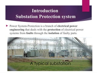
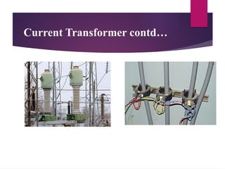
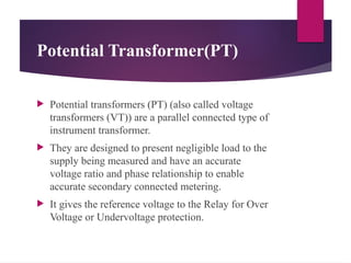
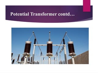
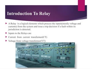
SEMINAR PRESENTATION
ON
“SUBSTATION PROTECTION DEVICES”
Presented by:
PRINCE KUMAR
ROLLNO- 2021031164
3RD
YEAR (SEC-B)
ELECTRICAL ENGINEERING
MADAN MOHAN MALVIYA UNIVERSITY OF TECHNOLOGY
Contents
 Introduction
 Protection devices
 Protection requirement
 Current transformer(CT)
 Potential transformer(PT)
 Relay
 Circuit breaker
 Lightning arrester
 Isolators
 Conclusion
Introduction
Substation Protection system
 Power System-Protection is a branch of electrical power
engineering that deals with the protection of electrical power
systems from faults through the isolation of faulty parts.
A typical substation
Why Do We Need Protection
 The objective of a protection scheme is to keep the
power system stable by isolating only the
components that are under fault, whilst leaving as
much of the network as possible still in operation.
 Under abnormal working condition protection is
necessary for safety of electrical equipments and
safety of human being.
Switchgear And Protection Devices
 What are the Protection devices?
 The apparatus or equipments and their associated
auxiliaries employed for controlling, regulating and
switching on or off the electrical circuits in the
electrical power system is known as “Protection
devices” or “switchgear”.
 Protection devices protect the transmission lines,
generators, transformers and other electrical
equipments from various “faults”.
Three-Phase Diagram of the
Protection
CTs
VTs
Relay
CB
Control
Protected
Equipment
Components of switchgear
 Current Transformer
 Potential Transformer
 Relays
 Circuit breakers
 Lightning arresters(or “Surge diverter”)
 Isolators(or “Disconnecting switch”)
 Fuse
Current Transformer(CT)
 A current transformer (CT) is used for measurement
of alternating electric current.
 When current in a circuit is too high to apply directly to
measuring instruments, a current transformer produces
a reduced current accurately proportional to the current
in the circuit, which can be conveniently connected to
measuring and recording instruments.
 Current transformers are commonly used in metering
and protective relays in the electrical power industry.
Current Transformer contd…
Potential Transformer(PT)
 Potential transformers (PT) (also called voltage
transformers (VT)) are a parallel connected type of
instrument transformer.
 They are designed to present negligible load to the
supply being measured and have an accurate
voltage ratio and phase relationship to enable
accurate secondary connected metering.
 It gives the reference voltage to the Relay for Over
Voltage or Undervoltage protection.
Potential Transformer contd…
Introduction To Relay
 A Relay is a logical elements which process the inputs(mostly voltage and
currents) from the system and issue a trip decision if a fault within its
jurisdiction is detected.
 Inputs to the Relays are
 Current from current transformer(CT)
 Voltage from voltage transformer(VT)
Circuit Breaker(CB)
 Circuit breakers are an automatically operated electrical devices,
design to close or open contact members, thus closing and
opening an electrical circuit under normal or abnormal
conditions.
 It operates on relays command.
 It handles the large voltage and current.
 A circuit breaker consists of two contacts namely “fixed” and
“moving contacts” which touches each other under normal
condition i.e. when circuit breaker is closed.
Circuit breaker contd…
An Oil Circuit Breaker SF6 Circuit Breaker
Lightning arrester(Surge Diverter)
 The device or equipment used for the protection of the
power system against voltage surge is called “surge
diverter” or “lightning arrester”.
Isolators
 Isolators are used to isolate the high voltage from flow
through line into the bus. It allows only needed voltage
and rest is earth by itself if required.
Isolator
Conclusion
 The objective of the protection devices(system) is
to keep the power system stable by isolating only
the components that are under fault, while leaving
as much of the network as possible.
 Now a days the Substation Protection System is
fully automatic.
References
 Power system protection and switchgear by Badri
Ram TMH publication.
 Fundamentals of Power system protection by
Yashwant G. Paithankar, S.R. Bhide.
 Electrical Power system by A Wright.
 Wikipedia
Thank you...

PPT FINAL YEAR PRESENTATION ON SUBSTATION PROTECTION .pptx

  • 1.
    SEMINAR PRESENTATION ON “SUBSTATION PROTECTIONDEVICES” Presented by: PRINCE KUMAR ROLLNO- 2021031164 3RD YEAR (SEC-B) ELECTRICAL ENGINEERING MADAN MOHAN MALVIYA UNIVERSITY OF TECHNOLOGY
  • 2.
    Contents  Introduction  Protectiondevices  Protection requirement  Current transformer(CT)  Potential transformer(PT)  Relay  Circuit breaker  Lightning arrester  Isolators  Conclusion
  • 3.
    Introduction Substation Protection system Power System-Protection is a branch of electrical power engineering that deals with the protection of electrical power systems from faults through the isolation of faulty parts. A typical substation
  • 4.
    Why Do WeNeed Protection  The objective of a protection scheme is to keep the power system stable by isolating only the components that are under fault, whilst leaving as much of the network as possible still in operation.  Under abnormal working condition protection is necessary for safety of electrical equipments and safety of human being.
  • 5.
    Switchgear And ProtectionDevices  What are the Protection devices?  The apparatus or equipments and their associated auxiliaries employed for controlling, regulating and switching on or off the electrical circuits in the electrical power system is known as “Protection devices” or “switchgear”.  Protection devices protect the transmission lines, generators, transformers and other electrical equipments from various “faults”.
  • 6.
    Three-Phase Diagram ofthe Protection CTs VTs Relay CB Control Protected Equipment
  • 7.
    Components of switchgear Current Transformer  Potential Transformer  Relays  Circuit breakers  Lightning arresters(or “Surge diverter”)  Isolators(or “Disconnecting switch”)  Fuse
  • 8.
    Current Transformer(CT)  Acurrent transformer (CT) is used for measurement of alternating electric current.  When current in a circuit is too high to apply directly to measuring instruments, a current transformer produces a reduced current accurately proportional to the current in the circuit, which can be conveniently connected to measuring and recording instruments.  Current transformers are commonly used in metering and protective relays in the electrical power industry.
  • 9.
  • 10.
    Potential Transformer(PT)  Potentialtransformers (PT) (also called voltage transformers (VT)) are a parallel connected type of instrument transformer.  They are designed to present negligible load to the supply being measured and have an accurate voltage ratio and phase relationship to enable accurate secondary connected metering.  It gives the reference voltage to the Relay for Over Voltage or Undervoltage protection.
  • 11.
  • 12.
    Introduction To Relay A Relay is a logical elements which process the inputs(mostly voltage and currents) from the system and issue a trip decision if a fault within its jurisdiction is detected.  Inputs to the Relays are  Current from current transformer(CT)  Voltage from voltage transformer(VT)
  • 13.
    Circuit Breaker(CB)  Circuitbreakers are an automatically operated electrical devices, design to close or open contact members, thus closing and opening an electrical circuit under normal or abnormal conditions.  It operates on relays command.  It handles the large voltage and current.  A circuit breaker consists of two contacts namely “fixed” and “moving contacts” which touches each other under normal condition i.e. when circuit breaker is closed.
  • 14.
    Circuit breaker contd… AnOil Circuit Breaker SF6 Circuit Breaker
  • 15.
    Lightning arrester(Surge Diverter) The device or equipment used for the protection of the power system against voltage surge is called “surge diverter” or “lightning arrester”.
  • 16.
    Isolators  Isolators areused to isolate the high voltage from flow through line into the bus. It allows only needed voltage and rest is earth by itself if required. Isolator
  • 17.
    Conclusion  The objectiveof the protection devices(system) is to keep the power system stable by isolating only the components that are under fault, while leaving as much of the network as possible.  Now a days the Substation Protection System is fully automatic.
  • 18.
    References  Power systemprotection and switchgear by Badri Ram TMH publication.  Fundamentals of Power system protection by Yashwant G. Paithankar, S.R. Bhide.  Electrical Power system by A Wright.  Wikipedia
  • 19.