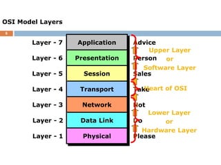
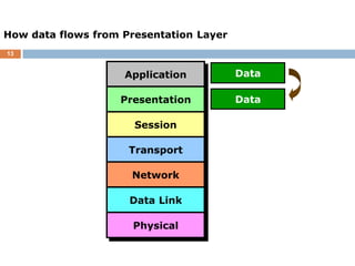
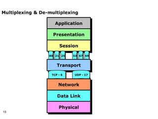
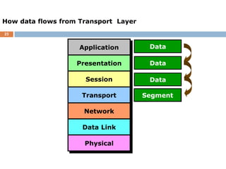
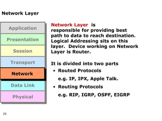
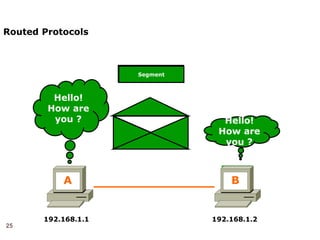
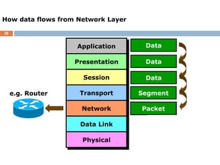
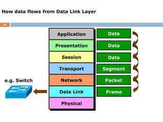
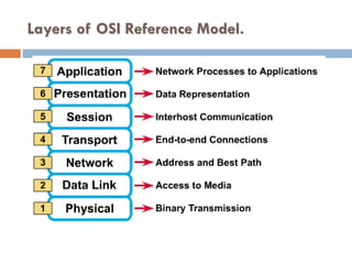
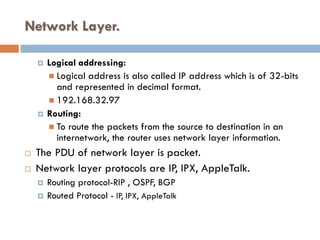
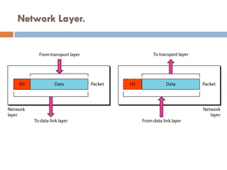
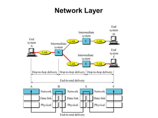
1
2
3
 OSI means Open System Interconnect model.
 Developed by the International Organization for
Standardization in 1974.
 It consists of seven layers.
 Each layer has a different but specific processing
function.
OSI Model
ISO - Organization for Standardization.
 International standards organisation is responsible
for a wide range of standards, including many that
are relevant to computer networking.
 In 1984 , the Open Systems Interconnection (OSI)
Reference Model was approved as an international
standard for communications architecture.
Figure. Tasks involved in sending a letter
6
Advice
Person
Sales
Take
Not
Do
Please
OSI Model Layers
Application
Presentation
Session
Transport
Network
Data Link
Physical
Layer - 7
Layer - 6
Layer - 5
Layer - 4
Layer - 3
Layer - 2
Layer - 1
Upper Layer
or
Software Layer
Lower Layer
or
Hardware Layer
Heart of OSI
7
Application Layer
Application Layer is
responsible for providing
Networking Services to user.
It also known as Desktop Layer.
Identification of Services is
done using Port Numbers.
e.g. HTTP,FTP, SMTP,
SIP,IMAP,DNS
Ports are nothing but Socket i.e.
Entry and Exit Point to the Layer
Total No. Ports 0 – 65535
Reserved Ports 0 – 1023
Open Ports 1024 – 65535
Application
Presentation
Session
Transport
Network
Data Link
Physical
Application
8
Examples of Networking Services
Service Port No.
HTTP 80
FTP 21
SMTP 25
TELNET 23
TFTP 69
9
Example of FTP request
Client FTP Server
ftp://ftp.microsoft.com
10
Example of FTP request
FTP Request
ftp://ftp.microsoft.com
FTP Request
Listen on
Port 21
Sending FTP Reply
Received FTP Reply
ftp://ftp.microsoft.com
Client FTP Server
11
Application
21
80 25 67
53 69
How data flows from Application Layer
Data
Presentation
Session
Transport
Network
Data Link
Physical
12
Presentation Layer
Presentation Layer is
responsible for converting data
into standard format.
Examples : ASCII, EBCDIC, JPEG,
MPEG, BMP, MIDI, WAV, MP3
Following tasks are perform at
Presentation layer :
Encoding – Decoding
Encryption – Decryption
Compression – Decompression
Application
Presentation
Session
Transport
Network
Data Link
Physical
Presentation
13
How data flows from Presentation Layer
Data
Data
Application
Presentation
Session
Transport
Network
Data Link
Physical
14
Session Layer
Session Layer is responsible
establishing, maintaining and
terminating session.
Session ID also works at Session
Layer.
Application
Presentation
Session
Transport
Network
Data Link
Physical
Session
15
How data flows from Session Layer
Data
Data
Data
Application
Presentation
Session
Transport
Network
Data Link
Physical
16
Transport Layer
Transport Layer is
responsible for end-to-end
connectivity. It is also known as
heart of OSI Layers. Following
task are performed at Transport
Layer : -
• Identifying Service
• Multiplexing & De-multiplexing
• Segmentation
• Sequencing & Reassembling
• Flow Control
• Error Detection
Application
Presentation
Session
Transport
Network
Data Link
Physical
Transport
17
Identifying Service
• Transmission Control
Protocol
• Connection Oriented
• Acknowledgement
• Reliable
• Slower
• Port No. 6
• e.g. HTTP, FTP, SMTP
• User Datagram
Protocol
• Connection Less
• No Acknowledgement
• Unreliable
• Faster
• Port No. 17
• e.g. DNS, DHCP,
TFTP,SNMP
TCP UDP
18
Application
Presentation
Session
Multiplexing & De-multiplexing
21
80 25 67
53 69
Transport
TCP - 6 UDP - 17
Network
Data Link
Physical
19
Segmentation
Hello! How are you ?
Hello! How Are You ?
Hello!
How are
you ?
A B
20
Sequencing & Reassembling
Hello! How are you ?
Hello!
1/5
How
2/5
Are
3/5
You
4/5
?
5/5
Hello!
How are
you ?
A B
Hello! How are you ?
Hello!
1/5
How
2/5
Are
3/5
You
4/5
?
5/5
Hello!
1/5
How
2/5
Are
3/5
You
4/5
?
5/5
Hello!
How are
you ?
21
Error Detection
Hello! How are you ?
Hello!
1/5
How
2/5
Are
3/5
You
4/5
?
5/5
Hello!
How are
you ? Hello!
1/5
Are
3/5
You
4/5
?
5/5
Hello!
1/5
Are
3/5
You
4/5
?
5/5
Segment Missing
Hello!
1/5
Are
3/5
You
4/5
?
5/5
How
2/5
How
2/5
Hello! How are you ? Hello!
How are
you ?
A B
22
Flow Control - Windowing
Sending
3-window
Received
3-window
Ack-Rec-
3
Sending
5-window
Received
4-window
A B
Ack.
Received-
4
PC-A
can send 4 Segment
at a time to
PC-B
23
How data flows from Transport Layer
Data
Data
Data
Data
TH
Segment
Application
Presentation
Session
Transport
Network
Data Link
Physical
24
Network Layer
Network Layer is
responsible for providing best
path to data to reach destination.
Logical Addressing sits on this
layer. Device working on Network
Layer is Router.
It is divided into two parts
• Routed Protocols
e.g. IP, IPX, Apple Talk.
• Routing Protocols
e.g. RIP, IGRP, OSPF, EIGRP
Application
Presentation
Session
Transport
Network
Data Link
Physical
Network
25
Routed Protocols
192.168.1.1 192.168.1.2
A B
Segment
Segment
Source IP
192.168.1.1
Destination IP
192.168.1.2
Source IP
192.168.1.1
Destination IP
192.168.1.2
Segment
Hello!
How are
you ?
Hello!
How are
you ?
26
How data flows from Network Layer
Data
Data
Data
Segment
Segment
NH
e.g. Router
Packet
Application
Presentation
Session
Transport
Network
Data Link
Physical
27
Datalink Layer
Data link Layer is
divided into two Sub Layers :
• LLC – Logical Link Control
It talks about Wan protocols e.g.
PPP, HDLC, Frame-relay
• MAC – Media Access Control
It talks about Physical Address.
It is 48 bit Addressing
i.e. 12 digit Hexadecimal No.
It is also responsible for Error
Detection
Device working on Data Link
Layer is Switch, Bridge, NIC.
Application
Presentation
Session
Transport
Network
Data Link
Physical
Data Link
28
Error Detection – CRC Check
Hello!
How are
you ?
Packet
Packet
Source MAC
00-20-18-C0-07-71
Destination MAC
00-20-18-C0-07-72
00000
32434
22222
89696
55434
99323
43434
99434
46323
11114
33333
00000
32434
22222
89696
55434
99323
43434
99434
46323
11114
Error Detected
192.168.1.1
00-20-18-C0-07-71
192.168.1.2
00-20-18-C0-07-72
A B
PC-A
CRC No. 33333
PC-B
CRC No. 11114
Error Detected
For Error Correction
Contact Source Transport layer
29
e.g. Switch
How data flows from Data Link Layer
Data
Data
Data
Segment
DH
Packet
DT
Application
Presentation
Session
Transport
Network
Data Link
Physical
Packet
Packet
Frame
30
Physical Layer
Physical Layer is
responsible for electrical,
mechanical or procedural checks.
Data will be converted in Binary
that is 0’s & 1’s. Data will be in the
form of electrical pulses if it is
Coaxial or Twisted Pair cable and in
the form of Light if it is Fiber Optic
Cable.
Devices working at Physical Layer
are Hubs, Repeaters, Cables,
Modems etc.
Application
Presentation
Session
Transport
Network
Data Link
Physical
Physical
31
Physical Layer Example
Frame
Frame
1010101010101010
1010101010101010
Hello!
How are
you ?
A B
0101011010101010101010101
1010101101010101010101010
0101011010101010101010101
1010101101010101010101010
0101011010101010101010101
Frame
32
How data flows from Physical Layer
Data
Data
Data
Segment
Packet
Frame
Bits
e.g. Hub
Application
Presentation
Session
Transport
Network
Data Link
Physical
Encapsulation.
Layers of OSI Reference Model.
35
Segment
Packet
Frame
A B
Packet
Data
Data
Data
Bits
Data
Segment
Data Encapsulation & De-capsulation
Packet
Data
Data
Data
Application
Presentation
Session
Transport
Network
Data Link
Physical
Application
Presentation
Session
Transport
Network
Data Link
Physical
Bits
DH DT
NH
TH
Segment
Packet
DT Packet
DH DT
DH
NH Segment NH
TH Data
TH
Frame Packet
36
Application
Transport
Internet
Network
Access
Comparing OSI with TCP/IP Layers
OSI Layers TCP/IP Layers
Application
Presentation
Session
Transport
Network
Data Link
Physical
OSI Layers (1)
 Physical
 Bottommost layer
 Implements an unreliable bit link
 Uses synchronization bits to synchronize the receiver
 Specify the modulation scheme
 Physical interface between devices
 Mechanical
 Electrical
 Functional
 Procedural
 For activating, maintaining and deactivating the physical link
between communicating network systems
Data Link Layer.
 The data link layer is responsible for moving frames from
one hop (node) to the next.
 The major duties of the data link layer are:
 Framing
 Physical addressing:
 Physical address is the MAC address, which is hard coded
into NIC and is of 48-bit represented by Hexadecimal
format.
 00.27.AB.CC.EE.23
00.27.AB-Vendor
CC.EE.23-User
 Cmd Ipconfig/all to show the system details
 Flow control
 Error Control
 Access Control
 Data Link layer protocols are CSMA/CD, CSMA/CA, Token passing etc.
OSI Layers (2)
 Data Link
 Supervises transmission of packets by physical layer
 Means of activating, maintaining and deactivating a reliable link
 Adds sequence number and CRC
 Error detection and control
 Encapsulation and Decapsulation are performed
 Regulates the access to the link
 Higher layers may assume error free transmission
 A) Medium Access Control
MAC address will be added
B) Logical Link Control
CRC will be added
Data Link Layer.
Data Link Layer
Network Layer.
 The network layer is responsible for the source -to-
destination delivery of a packet possibly across
multiple networks.
 It two systems are connected to the same link, there is
usually no need for a network layer.
 However, if the two systems are attached to different
networks with connecting devices between the networks,
there is need for the network layer to accomplish the
delivery.
 The major duties performed by the network layer
are:
Network Layer.
 Logical addressing:
 Logical address is also called IP address which is of 32-bits
and represented in decimal format.
 192.168.32.97
 Routing:
 To route the packets from the source to destination in an
internetwork, the router uses network layer information.
 The PDU of network layer is packet.
 Network layer protocols are IP, IPX, AppleTalk.
 Routing protocol-RIP , OSPF, BGP
 Routed Protocol - IP, IPX, AppleTalk
which layer ?
Which Layer ?
Example
Network Layer.
Network Layer

6-OSI Model - ISO - Organization for Standardization.

  • 1.
  • 2.
  • 3.
    3  OSI meansOpen System Interconnect model.  Developed by the International Organization for Standardization in 1974.  It consists of seven layers.  Each layer has a different but specific processing function. OSI Model
  • 4.
    ISO - Organizationfor Standardization.  International standards organisation is responsible for a wide range of standards, including many that are relevant to computer networking.  In 1984 , the Open Systems Interconnection (OSI) Reference Model was approved as an international standard for communications architecture.
  • 5.
    Figure. Tasks involvedin sending a letter
  • 6.
    6 Advice Person Sales Take Not Do Please OSI Model Layers Application Presentation Session Transport Network DataLink Physical Layer - 7 Layer - 6 Layer - 5 Layer - 4 Layer - 3 Layer - 2 Layer - 1 Upper Layer or Software Layer Lower Layer or Hardware Layer Heart of OSI
  • 7.
    7 Application Layer Application Layeris responsible for providing Networking Services to user. It also known as Desktop Layer. Identification of Services is done using Port Numbers. e.g. HTTP,FTP, SMTP, SIP,IMAP,DNS Ports are nothing but Socket i.e. Entry and Exit Point to the Layer Total No. Ports 0 – 65535 Reserved Ports 0 – 1023 Open Ports 1024 – 65535 Application Presentation Session Transport Network Data Link Physical Application
  • 8.
    8 Examples of NetworkingServices Service Port No. HTTP 80 FTP 21 SMTP 25 TELNET 23 TFTP 69
  • 9.
    9 Example of FTPrequest Client FTP Server ftp://ftp.microsoft.com
  • 10.
    10 Example of FTPrequest FTP Request ftp://ftp.microsoft.com FTP Request Listen on Port 21 Sending FTP Reply Received FTP Reply ftp://ftp.microsoft.com Client FTP Server
  • 11.
    11 Application 21 80 25 67 5369 How data flows from Application Layer Data Presentation Session Transport Network Data Link Physical
  • 12.
    12 Presentation Layer Presentation Layeris responsible for converting data into standard format. Examples : ASCII, EBCDIC, JPEG, MPEG, BMP, MIDI, WAV, MP3 Following tasks are perform at Presentation layer : Encoding – Decoding Encryption – Decryption Compression – Decompression Application Presentation Session Transport Network Data Link Physical Presentation
  • 13.
    13 How data flowsfrom Presentation Layer Data Data Application Presentation Session Transport Network Data Link Physical
  • 14.
    14 Session Layer Session Layeris responsible establishing, maintaining and terminating session. Session ID also works at Session Layer. Application Presentation Session Transport Network Data Link Physical Session
  • 15.
    15 How data flowsfrom Session Layer Data Data Data Application Presentation Session Transport Network Data Link Physical
  • 16.
    16 Transport Layer Transport Layeris responsible for end-to-end connectivity. It is also known as heart of OSI Layers. Following task are performed at Transport Layer : - • Identifying Service • Multiplexing & De-multiplexing • Segmentation • Sequencing & Reassembling • Flow Control • Error Detection Application Presentation Session Transport Network Data Link Physical Transport
  • 17.
    17 Identifying Service • TransmissionControl Protocol • Connection Oriented • Acknowledgement • Reliable • Slower • Port No. 6 • e.g. HTTP, FTP, SMTP • User Datagram Protocol • Connection Less • No Acknowledgement • Unreliable • Faster • Port No. 17 • e.g. DNS, DHCP, TFTP,SNMP TCP UDP
  • 18.
    18 Application Presentation Session Multiplexing & De-multiplexing 21 8025 67 53 69 Transport TCP - 6 UDP - 17 Network Data Link Physical
  • 19.
    19 Segmentation Hello! How areyou ? Hello! How Are You ? Hello! How are you ? A B
  • 20.
    20 Sequencing & Reassembling Hello!How are you ? Hello! 1/5 How 2/5 Are 3/5 You 4/5 ? 5/5 Hello! How are you ? A B Hello! How are you ? Hello! 1/5 How 2/5 Are 3/5 You 4/5 ? 5/5 Hello! 1/5 How 2/5 Are 3/5 You 4/5 ? 5/5 Hello! How are you ?
  • 21.
    21 Error Detection Hello! Howare you ? Hello! 1/5 How 2/5 Are 3/5 You 4/5 ? 5/5 Hello! How are you ? Hello! 1/5 Are 3/5 You 4/5 ? 5/5 Hello! 1/5 Are 3/5 You 4/5 ? 5/5 Segment Missing Hello! 1/5 Are 3/5 You 4/5 ? 5/5 How 2/5 How 2/5 Hello! How are you ? Hello! How are you ? A B
  • 22.
    22 Flow Control -Windowing Sending 3-window Received 3-window Ack-Rec- 3 Sending 5-window Received 4-window A B Ack. Received- 4 PC-A can send 4 Segment at a time to PC-B
  • 23.
    23 How data flowsfrom Transport Layer Data Data Data Data TH Segment Application Presentation Session Transport Network Data Link Physical
  • 24.
    24 Network Layer Network Layeris responsible for providing best path to data to reach destination. Logical Addressing sits on this layer. Device working on Network Layer is Router. It is divided into two parts • Routed Protocols e.g. IP, IPX, Apple Talk. • Routing Protocols e.g. RIP, IGRP, OSPF, EIGRP Application Presentation Session Transport Network Data Link Physical Network
  • 25.
    25 Routed Protocols 192.168.1.1 192.168.1.2 AB Segment Segment Source IP 192.168.1.1 Destination IP 192.168.1.2 Source IP 192.168.1.1 Destination IP 192.168.1.2 Segment Hello! How are you ? Hello! How are you ?
  • 26.
    26 How data flowsfrom Network Layer Data Data Data Segment Segment NH e.g. Router Packet Application Presentation Session Transport Network Data Link Physical
  • 27.
    27 Datalink Layer Data linkLayer is divided into two Sub Layers : • LLC – Logical Link Control It talks about Wan protocols e.g. PPP, HDLC, Frame-relay • MAC – Media Access Control It talks about Physical Address. It is 48 bit Addressing i.e. 12 digit Hexadecimal No. It is also responsible for Error Detection Device working on Data Link Layer is Switch, Bridge, NIC. Application Presentation Session Transport Network Data Link Physical Data Link
  • 28.
    28 Error Detection –CRC Check Hello! How are you ? Packet Packet Source MAC 00-20-18-C0-07-71 Destination MAC 00-20-18-C0-07-72 00000 32434 22222 89696 55434 99323 43434 99434 46323 11114 33333 00000 32434 22222 89696 55434 99323 43434 99434 46323 11114 Error Detected 192.168.1.1 00-20-18-C0-07-71 192.168.1.2 00-20-18-C0-07-72 A B PC-A CRC No. 33333 PC-B CRC No. 11114 Error Detected For Error Correction Contact Source Transport layer
  • 29.
    29 e.g. Switch How dataflows from Data Link Layer Data Data Data Segment DH Packet DT Application Presentation Session Transport Network Data Link Physical Packet Packet Frame
  • 30.
    30 Physical Layer Physical Layeris responsible for electrical, mechanical or procedural checks. Data will be converted in Binary that is 0’s & 1’s. Data will be in the form of electrical pulses if it is Coaxial or Twisted Pair cable and in the form of Light if it is Fiber Optic Cable. Devices working at Physical Layer are Hubs, Repeaters, Cables, Modems etc. Application Presentation Session Transport Network Data Link Physical Physical
  • 31.
    31 Physical Layer Example Frame Frame 1010101010101010 1010101010101010 Hello! Howare you ? A B 0101011010101010101010101 1010101101010101010101010 0101011010101010101010101 1010101101010101010101010 0101011010101010101010101 Frame
  • 32.
    32 How data flowsfrom Physical Layer Data Data Data Segment Packet Frame Bits e.g. Hub Application Presentation Session Transport Network Data Link Physical
  • 33.
  • 34.
    Layers of OSIReference Model.
  • 35.
    35 Segment Packet Frame A B Packet Data Data Data Bits Data Segment Data Encapsulation& De-capsulation Packet Data Data Data Application Presentation Session Transport Network Data Link Physical Application Presentation Session Transport Network Data Link Physical Bits DH DT NH TH Segment Packet DT Packet DH DT DH NH Segment NH TH Data TH Frame Packet
  • 36.
    36 Application Transport Internet Network Access Comparing OSI withTCP/IP Layers OSI Layers TCP/IP Layers Application Presentation Session Transport Network Data Link Physical
  • 37.
    OSI Layers (1) Physical  Bottommost layer  Implements an unreliable bit link  Uses synchronization bits to synchronize the receiver  Specify the modulation scheme  Physical interface between devices  Mechanical  Electrical  Functional  Procedural  For activating, maintaining and deactivating the physical link between communicating network systems
  • 38.
    Data Link Layer. The data link layer is responsible for moving frames from one hop (node) to the next.  The major duties of the data link layer are:  Framing  Physical addressing:  Physical address is the MAC address, which is hard coded into NIC and is of 48-bit represented by Hexadecimal format.  00.27.AB.CC.EE.23 00.27.AB-Vendor CC.EE.23-User  Cmd Ipconfig/all to show the system details  Flow control  Error Control  Access Control  Data Link layer protocols are CSMA/CD, CSMA/CA, Token passing etc.
  • 39.
    OSI Layers (2) Data Link  Supervises transmission of packets by physical layer  Means of activating, maintaining and deactivating a reliable link  Adds sequence number and CRC  Error detection and control  Encapsulation and Decapsulation are performed  Regulates the access to the link  Higher layers may assume error free transmission  A) Medium Access Control MAC address will be added B) Logical Link Control CRC will be added
  • 40.
  • 41.
  • 42.
    Network Layer.  Thenetwork layer is responsible for the source -to- destination delivery of a packet possibly across multiple networks.  It two systems are connected to the same link, there is usually no need for a network layer.  However, if the two systems are attached to different networks with connecting devices between the networks, there is need for the network layer to accomplish the delivery.  The major duties performed by the network layer are:
  • 43.
    Network Layer.  Logicaladdressing:  Logical address is also called IP address which is of 32-bits and represented in decimal format.  192.168.32.97  Routing:  To route the packets from the source to destination in an internetwork, the router uses network layer information.  The PDU of network layer is packet.  Network layer protocols are IP, IPX, AppleTalk.  Routing protocol-RIP , OSPF, BGP  Routed Protocol - IP, IPX, AppleTalk
  • 44.
  • 45.
  • 46.
  • 47.
  • 48.