Downloaded 20 times
![Introduction To RegionalTraining Centre (CNS), EasternRegionof AAI
Airports Authority of India (AAI) was constituted by an Act of Parliament and came into
being on 1st April 1995 by merging erstwhile National Airports Authority and International
Airports Authority of India. The merger brought into existence a single Organization
entrusted with the responsibility of creating, upgrading, maintaining and managing civil
aviation infrastructure both on the ground and air space in the country. It covers 2.8 million
square nautical miles area which includes oceanic area of 1.7 million square nautical miles.
During the year 2008-09, AAI handled aircraft movement of 1306532 nos. [International
270345 & domestic 33785990] and the cargo handled 499418 tones [international 318242
& domestic 181176].
Functions of AAI
The functions of AAI are as follows:
1. Design, Development, Operation and Maintenance of international and domestic
airports and civil enclaves.
2. Control and Management of the Indian airspace extending beyond the territorial limits
of the country, as accepted by ICAO.
3. Construction, Modification and Management of passenger terminals.](https://image.slidesharecdn.com/aeb627f4-b36b-4315-bc5e-f3252dfc050b-160903072401/85/report-4-320.jpg)
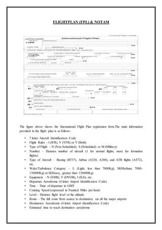

This document is a summer training report submitted by Amit Singh Rathore to Dr. Navneet Kumar Agrawal. It discusses Amit's training at the Maharana Pratap Airport in Udaipur under the Airports Authority of India (AAI). The report includes sections on the functions of AAI, Communication Navigation Surveillance systems, flight plans and NOTAMs, VHF and HFRT communication, the Automatic Message Switching System, instrumentation systems like ILS and radar, and concludes with a discussion of ADS and CPDLC technologies. It provides an overview of the various communication, navigation and air traffic control systems used at Indian airports.


![A presentation on internship from jaipur Airport [AAI]](https://cdn.slidesharecdn.com/ss_thumbnails/airportpptbyadityasept-160404162154-thumbnail.jpg?width=640&height=640&fit=bounds)


