Download to read offline
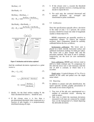
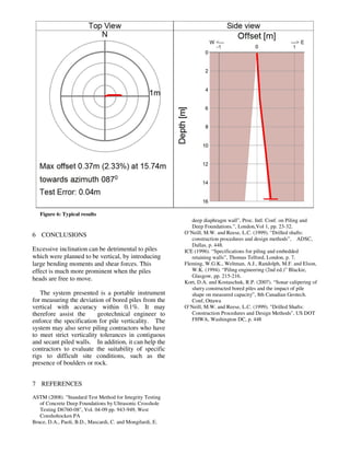

The document describes a new system called the BIT (Borehole Inclination Tester) for testing the inclination of bored piles. It consists of sensors mounted on a drilling bucket or access tube that can measure the pile's inclination at various depths. Finite element modeling showed that even small deviations from verticality can cause excessive stresses in piles. While specifications limit maximum inclination, existing testing methods have drawbacks. The BIT addresses these by providing a portable, automated system for measuring inclination during drilling and after completion. Initial field tests demonstrate its viability for quickly checking pile alignment compliance with specifications.


