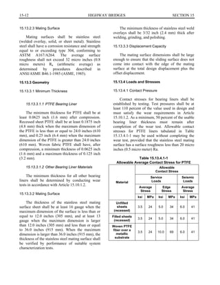
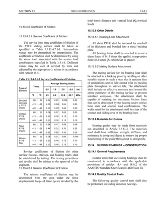
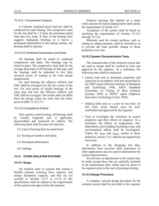
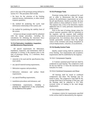
Download to read offline

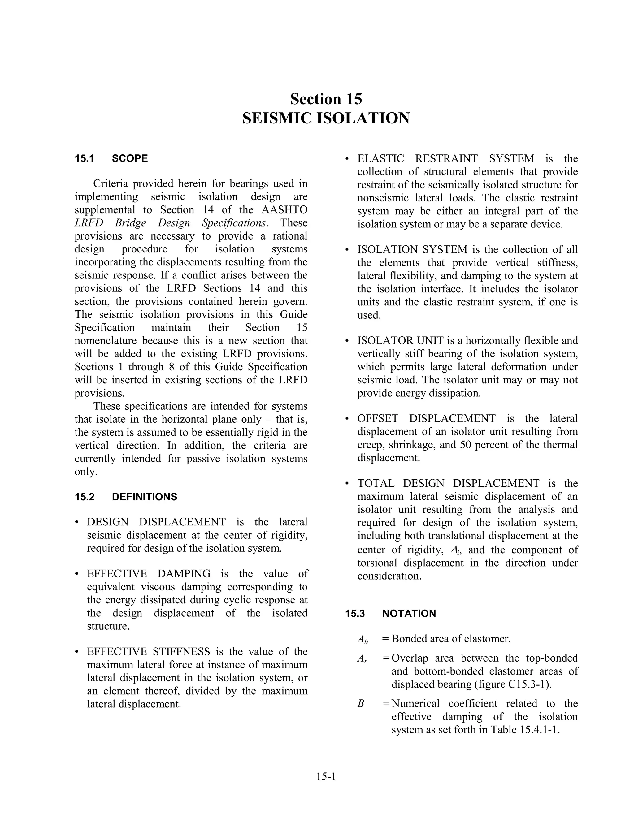
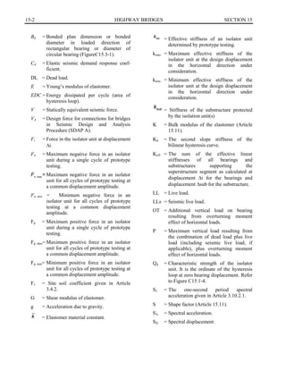
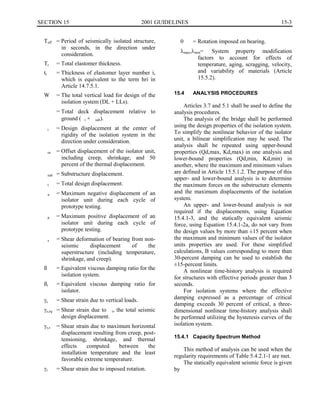

This document provides definitions and analysis procedures for seismic isolation design. Some key points: - It outlines criteria for bearings used in seismic isolation design that supplement other AASHTO specifications. - The criteria are intended for horizontal isolation systems using passive isolator units to provide flexibility and damping. - It defines terms related to seismic isolation like design displacement, effective damping, isolator unit, etc. - Analysis procedures include using a bilinear model of the isolator, and performing upper and lower bound analyses with maximum and minimum isolator properties unless displacements and forces vary less than 15%. - For structures over 3 seconds, a nonlinear time-history analysis is required. Over 30% damping requires a