1) The document discusses reducing commutation torque ripple in brushless DC motors (BLDCMs) through controlling the input voltage. BLDCMs experience torque ripple during commutation intervals that depends on speed.
2) It proposes using a single-ended primary inductor converter (SEPIC) circuit before the inverter to generate the desired DC link voltage and control commutation torque ripple. This allows fast adjustment of the voltage during non-commutation periods.
3) Simulation results show the proposed method using SEPIC reduces commutation torque ripple at both high and low speeds more effectively than conventional DC-DC converters through faster regulation of the DC voltage.
The Journal of MC Square Scientific Research is published by MC Square Publication on the monthly basis. It aims to publish original research papers devoted to wide areas in various disciplines of science and engineering and their applications in industry. This journal is basically devoted to interdisciplinary research in Science, Engineering and Technology, which can improve the technology being used in industry. The real-life problems involve multi-disciplinary knowledge, and thus strong inter-disciplinary approach is the need of the research.
An Improved DTFC based Five Levels - NPC Inverter Fed Induction Motor for Tor...IJPEDS-IAES
This paper presents a five level Neutral Point Clamped (NPC) inverter fed
IM (Induction Motor) drive for variable speed application. In general the
stator current is very highly affected by the harmonic components. It can be
affecting the torque to produce high torque ripple in IM at maximum to low
speed region. Since the drive performances are depends on mathematical
model contains the parameters variations, noise, common mode voltage, flux
variation and harmonic levels of the machine. Torque ripples and voltage
saturations are the most significant problems in drive application. To
overcome this problem the DTFC (direct torque and flux control) technique
based five-level neutral-point-clamped (NPC-5L) approach is used. The
proposed control scheme uses to stator current error as variable. Through the
resistance estimated PI controller rules based the selection of voltage space
vector modulation technique is optimized and motor performance level has
been improved. The torque & speed are successfully controlled with less
torque response. The results are compared and verified with conventional
three phases VSI under different control technique by Matlab/Simulink.
Improved Torque Control Performance in Direct Torque Control using Optimal Sw...IJPEDS-IAES
This paper presents the significant improvement of Direct Torque Control (DTC) of 3-phases induction machine using a Cascaded H- Bidge Multilevel Inverter (CHMI). The largest torque ripple and variable switching frequency are known as the major problem founded in DTC of induction motor. As a result, it can diminish the performance induction motor control. Therefore, the conventional 2- level inverter has been replaced with CHMI the in order to increase the performance of the motor either in dynamic or steady-state condition. By using the multilevel inverter, it can produce a more selection of the voltage vectors. Besides that, it can minimize the torque ripple output as well as increase the efficiency by reducing the switching frequency of the inverter. The simulation model of the proposed method has been developed and tested by using Matlab software. Its improvements were also verified via experimental results.
Review of Improved Direct Torque Control Methodologies for Induction Motor Dr...AM Publications
ecoupled control of induction motor drives is possible using Direct Torque Control (DTC) method which
is very simple control strategy compared to field oriented control. In this method direct torque control is achieved by
selecting suitable inverter switching voltage vector from a lookup table. But drawback of this method is that it
produces toque ripples. Also the switching frequency of inverter switches is not constant. Many methods have been
proposed to address these issues of DTC. This paper reviews various methodologies which are suggested to improve
performance of basic DTC induction motor drive.
Total Harmonic Distortion Analysis of a Four Switch 3-Phase Inverter Fed Spee...IJPEDS-IAES
This paper investigates the performance of a Model reference adaptive system (MRAS) based cost-effective drive system of an induction motor (IM) for low-cost applications - high performance industrial drive systems. In this paper, the MRAS is used as a speed estimator and the motor is fed from a four-switch three-phase (FSTP) inverter instead of a conventional six- switch three-phase (SSTP) inverter. This configuration reduces the cost of the inverter, the switching losses, and the complexity of the control algorithms and interface circuits, the proposed control approach reduces the computation for real-time implementation. The robustness of the proposed MRAS-based FSTP inverter fed IM drive is verified by Experimental results at different operating conditions using digital signal processor (DSP1103) for a 1.1 Kw motor. A performance comparison of the proposed FSTP inverter fed IM drive with a conventional SSTP inverter system is also made in terms of speed response and total harmonic distortion (THD) of the stator current. The proposed FSTP inverter fed IM drive is found quite acceptable considering its performance, cost reduction and other advantages features.
Comparative Study of Fuzzy Logic Based Speed Control of Multilevel Inverter f...IJPEDS-IAES
This paper presents a comparative analysis of speed control of brushless DC motor (BLDC) drive fed with conventional two-level, three and five level diode clamped multilevel inverter (DC-MLI). The performance of the drive system is successfully evaluated using Fuzzy Logic (FL) based speed controller. The control structure of the proposed drive system is described. The speed and torque characteristic of conventional two-level inverter is compared with the three and five-level multilevel inverter (MLI) for various operating conditions. The three and five level diode clamped multilevel inverters are simulated using IGBT’s and the mathematical model of BLDC motor has been developed in MATLAB/SIMULINK environment. The simulation results show that the Fuzzy based speed controller eliminate torque ripples and provides fast speed response. The developed Fuzzy Logic model has the ability to learn instantaneously and adapt its own controller parameters based on disturbances with minimum steady state error, overshoot and rise time of the output voltage.
This paper proposes new topology of five-phase inverter with reduced number of switches fed indirect rotor field oriented five phase induction motor. It employs only eight IGBT switches preformed five phase inverter. The reduction of the number of power switches from ten to eight improves the cost-effectiveness, volume-compactness and reliability of five-phase induction motor drive system. Simulation model of the proposed drive system is developed using the Matlab/Simulink package and analyzed to verify the effectiveness at different operating conditions of this approach. The comparison between the performance of the five phase motor under classical ten switch inverter and new topology at the same operation conditions has been illustrated. The proposed system gives similar operations as classical ten switch inverter for a certain range of motor speed and load torque. The DC voltage of proposed inverter must be compensated to higher value to achieve same performance of classical ten switch inverter in all range of motor speed and load torque.
Brushless DC (BLDC) motors are becoming an increasingly popular motor of choice for its unique characteristics. The BLDC motor drive is assumed to have trapezoidal back-electromotive force (EMF), rectangular phase currents and together produces the desired torque. However, practical back-EMF waveform might not be exactly trapezoidal because of current ripple, design considerations and manufacturing limitations. The adverse effect is the torque ripple generated due to the current ripple that causes mechanical vibration, acoustic noise and affects the accuracy of speed and position control which is not desirable in motor operation. In this paper an algorithm is developed to control and minimize the generated torque ripple using Space Vector Pulse Width Modulation (SVPWM) scheme. The efficiency improvement of slim type BLDC motor is confirmed using MATLAB environment and low cost TI Piccolo F28035 microcontroller (MC).
Brushless DC motor Drive during Speed regulation with Current ControllerIJERA Editor
Brushless DC Motor (BLDC) is one of the best electrical drives that have increasing popularity, due to their
high efficiency, reliability, good dynamic response and very low maintenance. Due to the increasing demand for
compact & reliable motors and the evolution of low cost power semiconductor switches and permanent magnet
(PM) materials, brushless DC motors become popular in every application from home appliances to aerospace
industry. The conventional techniques for controlling the stator phase current in a brushless DC drive are
practically effective in low speed and cannot reduce the commutation torque ripple in high speed range. This
paper presents the PI controller for speed control of BLDC motor. The output of the PI controllers is summed
and is given as the input to the current controller. The BLDC motor is fed from the inverter where the rotor
position and current controller is the input. The complete model of the proposed drive system is developed and
simulated using MATLAB/Simulink software. The operation principle of using component is analysed and the
simulation results are presented in this to verify the theoretical analysis.
International Journal of Engineering Research and Applications (IJERA) is an open access online peer reviewed international journal that publishes research and review articles in the fields of Computer Science, Neural Networks, Electrical Engineering, Software Engineering, Information Technology, Mechanical Engineering, Chemical Engineering, Plastic Engineering, Food Technology, Textile Engineering, Nano Technology & science, Power Electronics, Electronics & Communication Engineering, Computational mathematics, Image processing, Civil Engineering, Structural Engineering, Environmental Engineering, VLSI Testing & Low Power VLSI Design etc.
Comparative Performance Study for Closed Loop Operation of an Adjustable Spee...IJPEDS-IAES
In this paper an extensive comparative study is carried out between PI
and PID controlled closed loop model of an adjustable speed Permanent
Magnet Synchronous Motor (PMSM) drive. The incorporation of Sinusoidal
Pulse Width Modulation (SPWM) strategy establishes near sinusoidal
armature phase currents and comparatively less torque ripples without
sacrificing torque/weight ratio. In this closed loop model of PMSM drive, the
information about reference speed is provided to a speed controller, to ensure
that actual drive speed tracks the reference speed with ideally zero steady
state speed error. The entire model of PMSM closed loop drive is divided
into two loops, inner loop current and outer loop speed. By taking the
different combinations of two classical controllers (PI & PID) related with
two loop control structure, different approximations are carried out. Hence a
typical comparative study is introduced to familiar with the different
performance indices of the system corresponding to time domain and
frequency domain specifications. Therefore overall performance of closed
loop PMSM drive is tested and effectiveness of controllers will be
determined for different combinations.
Computation of Equivalent Moment of Inertia Due to Controlled Frequency in Ca...IDES Editor
In order to eliminate bulky flywheels from the
process machine having loads with severe torque fluctuations
can be driven by an induction motor with control of input
frequency using VVVf inverters. Situation of rise in load
torque can be met by reduction in frequency at that instant.
Situation of sudden reduction in load torque can be met by
increase in frequency, at that instant. This paper deals with
computations for such cases using the graphical relation
between torque and speed, finally leading to a plot of
instantaneous motor torque as a function of time. Based on
this experimental work is carried out by giving reduced
frequency at the instant applying peak load.
In this paper, several methods are developed to control the brushless DC (BLDC) motor speed. Since it is difficult to get a good showing by utilizing classical PID controller, the Dynamic Wavelet Neural Network (DWNN) is the proposed work in this paper, with parallel PID controller to obtain an novel controller named DWNN-PID controller. It collects the artificial neural ability of its networks for imparting from motor of BLDC with drive system and the ability of identification for the wavelet decomposition and control of the dynamic system furthermore to have ability for adapting and self-learning. The suggested controller method is utilizing to control the speed of BLDC motor of which supply a better showing than utilizing classical controllers with a wide range of control. The proposed controller parameters are matched continuously using Particle Swarm Optimization (PSO) algorithm. The simulation results based on proposed DWNN-PID controller demonstrate a superior in the stability and performance compared at utilizing classical WNN-PID and conventional PID controllers. The simulation results are accomplished using Matlab/Simulink. It shows that the proposed control scheme has a superior performance.
FPGA-Based Implementation Nonlinear Backstepping Control of a PMSM DriveIJPEDS-IAES
In this paper, we present a new contribution of FPGAs (Field-Programmable Gate Array) for control of electrical machines. The adaptative Backstepping control approach for a permanent magnet synchronous motor drive is discussed and analyzed. We present a Matlab&Simulink simulation and experimental results from a benchmark based on FPGA. The Backstepping technique provides a systematic method to address this type of problem. It combines the notion of Lyapunov function and a controller procedure recursively. First, the adaptative and no adaptative Backstepping control approach is utilized to obtain the robustness for mismatched parameter uncertainties. The overall stability of the system is shown using Lyapunov technique. The simulation results clearly show that the proposed scheme can track the speed reference. Secondly, some experimental results are demonstrated to validate the proposed controllers. The experimental results carried from a prototyping platform are given to illustrate the efficiency and the benefits of the proposed approach and the various stages of implementation of this structure in FPGA.
A VARIABLE SPEED PFC CONVERTER FOR BRUSHLESS SRM DRIVEIJCI JOURNAL
In many industrial applications Switched Reluctance Motor (SRM) is mainly used because of its high
efficiency and low maintenance. Its mechanical structure is so simple to construct because it has salient
poles, stator and rotor. Stator has concentrated winding and there is no winding on rotor. So therefore no
need of commutator and brushes. The SRM drive has another advantage of fast dynamic response and fault
tolerant capability. However since this drive requires DC excitation so we need to convert AC-DC, this ACDC
conversion imposes low power factor on grid side and this leads to high losses. Here we have consider
air-compressor used for household applications. In this paper we are proposing PWM rectifier on AC side
for Power factor correction the same rectifier is used for control of DC-link voltage. Also SRM motor is
Driven by Asymmetrical converter, the speed of the Motor is changed by changing the DC-link voltage of
Asymmetrical converter. A MATLAB/SIMULINK based model is developed for various loading conditions
and simulation results are presented.
Improved Rotor Speed Brushless DC Motor Using Fuzzy Controllerijeei-iaes
A brushless DC (BLDC) Motors have advantages over brushed, Direct current (DC) Motors and , Induction motor (IM). They have better speed verses torque characteristics, high dynamic response, high efficiency, long operating life, noiseless operation, higher speed ranges, and rugged construction. Also, torque delivered to motor size is higher, making it useful in application where space and weight are critical factors. With these advantages BLDC motors find wide spread application in automotive appliance, aerospace medical, and instrumentation and automation industries This paper can be seen as fuzzy controllers compared to PI control BLDC motor rotor speed has improved significantly and beter result can be achieve.
MODELLING AND IMPLEMENTATION OF AN IMPROVED DSVM SCHEME FOR PMSM DTCpaperpublications3
Abstract: A very widely used drive strategy for PMSM is the field oriented control (FOC), which was proposed in 1971 for induction motors (IMs). However, the FOC scheme is quite complex due to the reference frame transformation and its high dependence upon the motor parameters and speed. To mitigate these problems, a new control strategy for the torque control of induction motor was developed by Takahashi known as the direct torque control (DTC) and by Depenbrock as the direct self control (DSC). The basic direct torque control (DTC) scheme may cause undesired torque, flux and current ripples because of the small number of applicable voltage vectors. The control system should be able to generate any voltage vector, implying the use of space vector modulation (SVM) which complicates the control scheme. The discrete space vector modulation (DSVM) method was proposed for DTC to overcome this problem which replaces the simple switching table by several switching tables, to apply a combination of three voltage vectors in the same sampling period. In this paper, after a brief review of the primary concept of DSVM DTC technique, a new scheme of DSVM DTC for PMSM is proposed with a new set of switching tables taking into account the motor speed and the absolute values of torque and flux feedback errors. In one fixed sampling time interval, three vectors are applied to the motor including the two null vectors. Comparisons of the basic DTC and the improved DSVM DTC schemes are made based on the system performance and switching loss. For this purpose the DSVM technique uses prefixed time intervals within a sampling cycle to synthesize a higher number of voltage vectors than the basic DTC scheme. A set of switching table is carried out to minimize the torque error. An optimal vector selector is developed to reduce the switching loss and make the system more stable. The sampling period does not need to be doubled in order to achieve a mean switching frequency practically equal to that of the basic DTC scheme. For a comparable performance, the switching loss of the proposed scheme is less than that of the basic DTC method. The vector application sequence is investigated and an optimal algorithm is developed to reduce the switching loss and torque ripple. Simulation and experiments on the improved DSVM DTC are carried out and compared with those on the basic DTC scheme.
Reduction of circulating current is one of the major considerations in inverter fed electrical drives. Diode clamped MLI enables higher output current per phase, thereby rating of the drive gets increased effectively. Various methods of triggering in the inverter legs creates better voltage profile and leads to the enabling of circulating current in the drive system. The induced circulating current flows through the apparatus neutral (N) and supply ground (G) is caused by the existence of parasitic capacitance. This circulating current may cause potential danger especially when parasitic capacitance poses large. In the past, different modulation techniques and conversion topologies have been introduced to minimize the flow of circulating current. However, these techniques lead to complexity, high cost, low voltage profile and efficiency due to lower modulation parameters. This paper proposes PS, POD, PD carrier shifting PWM algorithms for diode clamped MLI to tumbling the circulating current within the each phase of inverter legs. The performances of proposed algorithm, in terms of circulating current, THD, losses and efficiencies are analyzed theoreticallyand are validated via simulation and experimental results.
Closed Loop Speed Control of a BLDC Motor Drive Using Adaptive Fuzzy Tuned PI...IJERA Editor
Brushless DC Motors are widely used for many industrial applications because of their high efficiency, high
torque and low volume. This paper proposed an improved Adaptive Fuzzy PI controller to control the speed of
BLDC motor. This paper provides an overview of different tuning methods of PID Controller applied to control
the speed of the transfer function model of the BLDC motor drive and then to the mathematical model of the
BLDC motor drive. It is difficult to tune the parameters and get satisfied control characteristics by using normal
conventional PI controller. The experimental results verify that Adaptive Fuzzy PI controller has better control
performance than the conventional PI controller. The modeling, control and simulation of the BLDC motor have
been done using the MATLAB/SIMULINK software. Also, the dynamic characteristics of the BLDC motor (i.e.
speed and torque) as well as currents and voltages of the inverter components are observed by using the
developed model.
International Journal of Engineering Research and Applications (IJERA) is an open access online peer reviewed international journal that publishes research and review articles in the fields of Computer Science, Neural Networks, Electrical Engineering, Software Engineering, Information Technology, Mechanical Engineering, Chemical Engineering, Plastic Engineering, Food Technology, Textile Engineering, Nano Technology & science, Power Electronics, Electronics & Communication Engineering, Computational mathematics, Image processing, Civil Engineering, Structural Engineering, Environmental Engineering, VLSI Testing & Low Power VLSI Design etc.
Torque Ripple Minimization of a BLDC Motor Drive by Using Electronic Commutat...AI Publications
Brushless DC motors are having a major problem with harmonics in torque. The variations in speed and production of noise should be minimized by using proper topologies. BLDC motors have been gaining attention from different Industrial and domestic appliance manufacturers, because of their high efficiency, high power density and easy maintenance and low cost. This paper presents a three phase BLDC motor with low cost drive to be driven without DC link capacitor. The proposed technique uses an electronic commutation and operates the machine exclusive of the intermediate DC link capacitor. The designing of Brushless DC motor drive system along with control system for torque ripple minimization, speed controller and current controllers are presented using MATLAB / SIMULINK and results are evaluated.
Brushles DC motor are one type of motors that are rapidly gaining the popularity and are penetrating in industrial applications, home appliances, automotive, consumer, medical etc. Because of there many advantages such as high efficiency ,silent operation, compact form ,reliability, low maintenance (due to the absence of brushess), long operating life, high speed ranges etc. for the proper commution of current in inverter the rotar position information is necessary, this information is usually provided by the mechanical position sensors mounted within the motor. however it is well known that these position sensors have many drawbacks therefore a sensor less control of BLDC motor is developed which eliminates the sensing equipment ,reduces the cost of motor and increases the reliability of the BLDC motor. In this paper the position information is obtained from the zero crossing detection of the back EMF which is also called as the terminal voltage sensing method which is the simplest ,method of detecting the back EMF zero crossing ,here the motor voltages are sensed and give to the lowpass filter whose output is give to the ZCD which determines the zero crossing of the back EMF waveform and ZCD generates the signal required for the controller to provide the pulses for the inverter operation the controller used is a high performance controller(DSPic30F4011) which as both the features of microcontroller and digital signal processor .The complete model is simulated in MATLAB/SIMULINK software. the proposed hardware and simulation program are found to be efficient and the results are promising
IMPROVING POWER FACTORS BY USING LANDSMAN CONVERTER IN PMBLDC MOTORvivatechijri
Brushless DC in most commonly used motors in small scale applications like exhaust fans, Toys etc. The motor is supply by Voltage Source Inverter (VSI) with a dc-dc converter power factor correction circuit (PFC). Performance of dc-dc converters is analyzed and the results are discussed, third converter is best suited converter. By unity power factor the low-cost arrangement are provided. PID Logic Controller is utilized as the Controller for the BLDC motor. The Landsman Converter performs power factor correction and DC voltage control both are in a single controller. PFC converter improve the power quality in AC mains in wide range of speed and input AC voltage. In the PMBLDC Motor the electronic commutator of motor the Voltage Source Inverter is used.
DTC Scheme for a Four-Switch Inverter-Fed PMBLDC Motor Emulating the Six-Swit...IJRST Journal
The paper deals with the direct torque control (DTC) of brushless DC (BLDC) motor drives fed by four-switch three phase inverters (FSTPI) rather than six-switch inverters (SSTPI) in conventional drives. For any three phase inverter require six switches, but these switches are reduced to four. This reduction of power switches from six to four improves the reliability of the inverter, size of the inverter is reduced and cost of the inverter is also reduces. The FSTPI could be regarded as a reconfigured topology of the SSTPI in case of a switch/leg failure which represents a crucial reliability benefit for many applications especially in electric and hybrid propulsion systems. The DTC of FSTPI-fed BLDC motor drives is treated considering two strategies, such as: 1) DTC-1: a strategy inspired from the one intended to SSTPI-fed BLDC motor drives; 2) DTC-2: a strategy that considers a dedicated vector selection subtable in order to independently control the torques developed by the phases connected to the FSTPI legs during their simultaneous conduction. The operational principle of the four-switch BLDC motor drive and the developed control scheme are theoretically analyzed and the performance is demonstrated by simulation.
Model Attribute Check Company Auto PropertyCeline George
In Odoo, the multi-company feature allows you to manage multiple companies within a single Odoo database instance. Each company can have its own configurations while still sharing common resources such as products, customers, and suppliers.
This is a presentation by Dada Robert in a Your Skill Boost masterclass organised by the Excellence Foundation for South Sudan (EFSS) on Saturday, the 25th and Sunday, the 26th of May 2024.
He discussed the concept of quality improvement, emphasizing its applicability to various aspects of life, including personal, project, and program improvements. He defined quality as doing the right thing at the right time in the right way to achieve the best possible results and discussed the concept of the "gap" between what we know and what we do, and how this gap represents the areas we need to improve. He explained the scientific approach to quality improvement, which involves systematic performance analysis, testing and learning, and implementing change ideas. He also highlighted the importance of client focus and a team approach to quality improvement.
The Indian economy is classified into different sectors to simplify the analysis and understanding of economic activities. For Class 10, it's essential to grasp the sectors of the Indian economy, understand their characteristics, and recognize their importance. This guide will provide detailed notes on the Sectors of the Indian Economy Class 10, using specific long-tail keywords to enhance comprehension.
For more information, visit-www.vavaclasses.com
Welcome to TechSoup New Member Orientation and Q&A (May 2024).pdfTechSoup
In this webinar you will learn how your organization can access TechSoup's wide variety of product discount and donation programs. From hardware to software, we'll give you a tour of the tools available to help your nonprofit with productivity, collaboration, financial management, donor tracking, security, and more.
The French Revolution, which began in 1789, was a period of radical social and political upheaval in France. It marked the decline of absolute monarchies, the rise of secular and democratic republics, and the eventual rise of Napoleon Bonaparte. This revolutionary period is crucial in understanding the transition from feudalism to modernity in Europe.
For more information, visit-www.vavaclasses.com
Ethnobotany and Ethnopharmacology:
Ethnobotany in herbal drug evaluation,
Impact of Ethnobotany in traditional medicine,
New development in herbals,
Bio-prospecting tools for drug discovery,
Role of Ethnopharmacology in drug evaluation,
Reverse Pharmacology.
Palestine last event orientationfvgnh .pptxRaedMohamed3
An EFL lesson about the current events in Palestine. It is intended to be for intermediate students who wish to increase their listening skills through a short lesson in power point.
How to Make a Field invisible in Odoo 17Celine George
It is possible to hide or invisible some fields in odoo. Commonly using “invisible” attribute in the field definition to invisible the fields. This slide will show how to make a field invisible in odoo 17.
The Art Pastor's Guide to Sabbath | Steve ThomasonSteve Thomason
What is the purpose of the Sabbath Law in the Torah. It is interesting to compare how the context of the law shifts from Exodus to Deuteronomy. Who gets to rest, and why?
Students, digital devices and success - Andreas Schleicher - 27 May 2024..pptxEduSkills OECD
Andreas Schleicher presents at the OECD webinar ‘Digital devices in schools: detrimental distraction or secret to success?’ on 27 May 2024. The presentation was based on findings from PISA 2022 results and the webinar helped launch the PISA in Focus ‘Managing screen time: How to protect and equip students against distraction’ https://www.oecd-ilibrary.org/education/managing-screen-time_7c225af4-en and the OECD Education Policy Perspective ‘Students, digital devices and success’ can be found here - https://oe.cd/il/5yV
Students, digital devices and success - Andreas Schleicher - 27 May 2024..pptx
Bldc
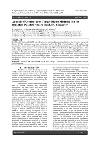
1. R.Jogarao et al. Int. Journal of Engineering Research and Application www.ijera.com
ISSN : 2248-9622, Vol. 6, Issue 11, ( Part -1) November 2016, pp.05-11
www.ijera.com 5 | P a g e
Analysis of Commutation Torque Ripple Minimization for
Brushless DC Motor Based on SEPIC Converter
R.Jogarao1
, Mouliswararao.Reddy2
, G.Ashok3
P.G. Student, Department of EEE, AITAM Engineering College(Autonomous),Andhra pradesh, India1
Asst.professor, Department of EEE, AITAM Engineering College(Autonomous),Andhra pradesh, India2
Asst.professor, Department of EEE, AITAM Engineering College(Autonomous),Andhra pradesh, India3
ABSTRACT
Brushless DC Motors (BLDCM) are widely used in automated industrial applications like Computer Numerical
Control (CNC) machinery, aerospace applications and in the field of robotics.But it still suffers from
commutation torque which mainly depends on speed and transient line commutation interval. BLDC MOTOR
torque ripple causes increased acoustic noise and undesirable speed fluctuation. This paper presents a new
circuit topology and dc link voltage current in the control strategy to keep incoming and outgoing phase currents
changing at the same rate during commutation. In this paper dc-dc single ended primary inductor converter
(SEPIC) a switch selection circuit are employed in front of inverter. In order to obtain the desired commutation
voltage resulting in reduced commutation torque ripple. Compared with simulation result conventional system
and proposed method can obtain desired voltage much faster and minimize commutation torque ripple more
efficiently.
Keywords: Brushless DC Motor(BLDCM),DC link voltage, Commutation, Single ended primary inductor
converter(SEPIC).
I. INTRODUCTION
Brushless dc motor (BLDCM) has been
widely used in industrial fields that require high
reliability and precise control due to its simple
structure. Brushless dc motor offer many attractive
features like low maintenance, fast response, high
efficiency, high power density, good reliability and
compact construction.
Brushless dc motor is increasingly being
used in military, industrial and commercial
applications. But these motors still suffer from
commutation torque ripple. The primary
disadvantage of brushless dc motor is higher torque
ripples compared with conventional machines. So
far many research studies have been performed to
reduce commutation torque ripple. An original
analytical study on commutation torque ripple is
presented in from which a conclusion has been
drawn that relative torque ripple is independent of
current and varies with speed. A similar analysis is
presented in and the strategy of changing the input
voltage to reduce commutation torque ripple in
BLDCM some necessary assumptions such as
ideal trapezoidal back electromotive force (EMF),
very small current hysteresis or pulse width
modulation (PWM) cycle, constant back EMF
during commutation no implementation of voltage
adjustment is demonstrated in them It is proposed
in that a single dc current sensor and a current
deadbeat control scheme should be used to keep
incoming and outgoing phase currents changing at
the same rate during commutation hence effectively
suppressing commutation torque ripple.
It is an effective method to introduce some
special topology of a circuit to BLDCM drives to
control its input voltage buck converter is used,
and commutation torque ripple is then greatly
reduced at low speed. In a super lift Luo converter
is placed at the entrance of the inverter to produce
desired dc link voltage and the structure is more
competent under the high-speed work condition,
compared with the method proposed in A
developed structure of the inverter is proposed in
which avoids the effect of the fly-wheeling process
and acquires more exact estimated torque with
sampling current. All of the above methods suffer
from slow voltage adjustment, and therefore, they
can only achieve satisfactory torque pulsation
suppression in low- or high-speed regions.
In this paper a new circuit is proposed an
appropriate dc link voltage is used to drive phase
currents to increase and decrease in the identical
slope resulting in the great reduction of pulsated
commutation torque. To get the desired dc link
voltage a single-ended primary inductor converter
(SEPIC) circuit is used to control the input of the
inverter. The adjustment of dc voltage can be
completed during non-commutation conduction
period and switched immediately at the beginning
of commutation by the switch selection circuit.
Simulation results are compared with common dc–
dc converter the proposed method when applied in
a steady state can reduce commutation torque
RESEARCH ARTICLE OPEN ACCESS
2. R.Jogarao et al. Int. Journal of Engineering Research and Application www.ijera.com
ISSN : 2248-9622, Vol. 6, Issue 11, ( Part -1) November 2016, pp.05-11
www.ijera.com 6 | P a g e
ripple both at high and low speeds with much faster
dc voltage regulation.
II. MATHEMATICAL MODEL OF
BLDC MOTOR DRIVE SYSTEM
A 3 phases, 4 poles, Y connected
trapezoidal back-EMF type BLDC is modeled.
Trapezoidal back-EMF is referring that mutual
inductance between stator and rotor has trapezoidal
shape. Therefore a b c phase variable model is
more applicable than d-q axis. With the intention of
simplifying equations and overall model the
following.
Assumptions are made:
Magnetic circuit saturation is ignored.
Stator resistance, self and mutual inductance of
all phases are equal and constant.
Hysteresis and eddy current losses are
eliminated.
All semiconductor switches are ideal.
The electrical and mechanical
mathematical equations of BLDC are:
Phase voltage equations of BLDC motor
)2.2...(..............................)( b
b
bb
E
dt
di
MLRiV
Back emf equations of BLDC motor
Torque equations are each phase of BLDC motor
Electromagentic torque equation BLDC motor
)10.2.....(........................................caae
TTTT
III. ANALYSIS OF TORQUE DURING
COMMUTATION INTERVAL
Fig3.1: Block diagram BLDCM drive system
The commonly used commutation in 3
phase BLDC motor is the six-step, in which each
phase voltage is energized for interval of 120
degree electrical according to therotor electrical
position. At any sector, only one phase is energized
as positive and one of the other phases is energized
as negative in order to maintain a current path. For
control the BLDC motor a typical 3 phase full
bridge will be used to drive the motor.
For the analysis of commutation time, the
commutations of the current through two phases
are to be considered. Phase A will be switched off,
and the phase B will replace the A phase and the
third phase C will remain conducting.
In this analysis the commutation from
phase A to phase B will be considered. The current
transfer happens during the six-step, since A phase
switch is ON while B phase switch will be OFF,
and the third phase switch will remain conducting.
In this analysis the transition of conduction from
Phase A(+)/C(−) to B(+)/C(−) will be considered as
shown in figure 3.1. In this case the phase A is the
de-energized phase and phase B will be the
incoming energized phase and phase C is the
conducting phase.
The BLDCM has three stator windings
and permanent magnets on the rotor. Its voltage
equation of three windings with phase variables is
)1.3.(..............................
00
00
00
00
00
00
NO
NO
NO
C
B
A
C
B
A
C
B
A
C
B
A
U
U
U
e
e
e
i
i
i
dt
d
L
L
L
i
i
i
R
R
R
u
u
u
the electromagnetic torque is
)2.3.......(..............................
CCBBAA
e
ieieie
T
)1.2...(..............................)( a
a
aa
E
dt
di
MLRiV
)3.2...(..............................)( c
c
cc
E
dt
di
MLRiV
)4.2.(........................................).........( emea
FKE
)5.2...(..............................).........
3
2
(
emeb
FKE
)6.2...(..............................).........
3
4
(
emec
FKE
)7.2......(........................................eata
FiKT
)8.2......(..............................
3
2
ebtb
FiKT
)9.2.......(..............................
3
4
ectc
FiKT
)11.2.(........................................2
2
dt
d
dt
d
JTT
mm
le
)12.2....(............................................................
2
me
p
)13.2.......(............................................................
dt
d m
m
3. R.Jogarao et al. Int. Journal of Engineering Research and Application www.ijera.com
ISSN : 2248-9622, Vol. 6, Issue 11, ( Part -1) November 2016, pp.05-11
www.ijera.com 7 | P a g e
Where NO
U is the neutral point-to-ground
voltage, A
u , B
u and C
u are the terminal phase
voltages with respect to the power ground,
A
i , B
i and C
i are phase currents, A
e , B
e and
C
e are trapezoidal back EMFs, MLL s
is the
equivalent inductance of phase windings, Ls and M
are self-inductance and mutual inductance,
respectively, R is the resistance of the phase
windings, and Ω is the speed of the rotor.
According to (3.2), to produce a steady
electromagnetic torque, the sum of
, AA
ie , BB
ie ,and CC
ie has to be constant as far as a
certain speed is concerned. It implies that
rectangular phase currents are needed, which
should be in phase with the corresponding back
EMF. phase windings, the actual phase currents,
instead of the desired rectangular form, are in a
trapezoidal form with a finite rise time. In fact, the
different slopes of incoming and outgoing phases
have a direct influence on the commutation torque,
which can be illustrated using the following
analysis. For this analysis, the commutation of the
current from phase A to phase B is considered. this
current transfer is done by switching off VT1 and
switching on VT3, with VT2 remaining on. With
only a very small period of PWM, the current
through the winding of the motor between
commutations is regarded to be constant and equal
to Im. It implies that the initial Due to the nonzero
inductance of the stator values
of mCA
Iii and 0B
i are known at the
beginning of commutation.
Fig3.2: Equivalent circuit during commutation
interval
The equivalent circuit during commutation
is shown in Fig.3.1. According to Fig. 3.2, switch
K1 is off and K2 is on at point 1 before
commutation begins. During commutation, K1 is
switched on. Because A
i flows through the
freewheeling diode VD4, K2 is switched on at point
2, and when the commutation is over, K1 is on and
K2 is switched on at point 3 (suspended). K1 and K2
stand for the MOSFETs carrying on PWM
modulation when turned on.
Considering very short duration of
commutation, back EMFs are supposed to be
constant during commutation. Then, the voltage
initial values at the beginning of commutation can
be drawn as
follows ;0;;0 CdcBA
uUuu
;; mmA
EeEe B
and mC
Ee Then, the
voltage equation (3.1) can be rewritten as
)3.3(........................................
0
0
NOCdt
di
C
NOBdt
di
Bdc
NOAdt
di
A
UeLRi
UeLRiU
UeLRi
C
B
A
The neutral point voltage can be solved as follows:
)4.3.........(........................................).........(
3
1
mdcNO
EUU
The electromagnetic torque before commutation is
)5.3.....(........................................
2
mmCCBBAA
pree
EIieieie
T
When the frequency of PWM is high and
the PWM period is much shorter than the electrical
time constant L/R, the effect of R can be neglected.
Then, the slopes of phase currents are
approximately drawn by
)6.3.(..................................................
3
4
3
)(2
3
2
L
EU
dt
di
L
EU
dt
di
L
EU
dt
di
mdcC
mdcB
mdcA
Fig. 3.3 Current behavior during commutation
a) rfmdc
ttEU ,4
b) rfmdc
ttEU ,4
c) rfmdc
ttEU ,4
The time taken for A
i to vanish from the initial
value m
I is
4. R.Jogarao et al. Int. Journal of Engineering Research and Application www.ijera.com
ISSN : 2248-9622, Vol. 6, Issue 11, ( Part -1) November 2016, pp.05-11
www.ijera.com 8 | P a g e
)7.3..(........................................
2
3
mdc
m
f
EU
LI
t
The time taken for B
i to increase from 0 to m
I is
)8.3...(..................................................
)(2
3
mdc
m
r
EU
LI
t
According to (3.2), (3.6), and
0 CBA
iii during commutation, the
electromagnetic torque can be calculated as
)9.3....(........................................
3
42
t
L
EU
I
E
T
mdc
m
m
come
The relative torque ripple is given by
)10.3..(........................................
3
4
t
L
EU
TTT
mdc
preecomee
According to (3.2) and (3.6)–(3.10), the
following conclusions can be drawn.
1) If rfmdc
ttEU ,4 and the torque keeps
increasing during commutation.
2) If rfmdc
ttEU ,4 , and the torque keeps
decreasing during commutation.
3) If rfmdc
ttEU ,4 and the torque is
constant during commutation.
The current behaviors with different speeds are
shown in Fig.3.3
As can be seen in (3.6), the slopes of the
currents during commutation depend on the dc link
voltage dc
U and the maximum value of back EMF
m
E . m
E is proportional to speed and considered
constant during commutation. dc
U is generally
invariable due to uncontrollable rectification.
Consequently, dc
U = m
E4 cannot always be
satisfied during speed adjustment, which leads to
significant torque pulsation. In (3.10), the torque
rippleduring commutation is proportional to
dc
U − m
E4 |and the closer dc
U is to m
E4 at the
commutation interval, the little the torque ripple
becomes. In this paper, a new circuit topology is
proposed, which can reduce commutation torque
pulsation bykeeping dc
U close to m
E4 during
commutation.
IV. PROPOSED METHODS FOR
TORQUE RIPPLE MINIMIZATION
An adjustable dc link voltage is required
tomaintain mdc
EU 4 to avoid the commutation
torque pulsation. In this paper, a SEPIC converter
with a switchover MOSFET is used to implement
the dc link voltage adjustment, as can be seen in
Fig.4.1
Fig4.1: Configuration of BLDCM driving system
with a SEPIC converter
In Fig.4.1, 1
S , 2
S , and 3
S are all power
MOSFETs. By operating 1
S appropriately, the
energy storage components (i.e., 1
L , 2
L , 1
C , and
2
C ) of the SEPIC converter can be adjusted to get
the desired output voltage 2
S and 3
S are
switchover power MOSFETs used for choosing
between the input of inverter S
U and the output
voltage of the SEPIC converter 0
U , which can be
calculated as
SEPIC converter design parameters are
)1.4.(....................
22
)1(
12
)1(0
1
fI
DU
fI
D
D
DU
fI
DU
L
in
S
in
S
in
)2.4.....(........................................
2
)1(0
2
fI
DU
L
o
)3.4....(........................................
1
0 S
U
D
D
U
Where D is the duty ratio under the operation of
1
S .
When the iron losses are not taken into account,
m
E is proportional to speed, i.e.,
)4.4........(........................................ em
KE
where e
K is the back EMF coefficient
Then, the duty ratio of 1
S for satisfying
m
EU 40
can be calculated by
)5.4.(..................................................
4
4
eS
e
KU
K
D
According to (4.3), the duty ratio of
1
S corresponding to the desired dc link voltage can
be estimated by measuring the motor speed. To
achieve an immediate change of the input voltage
of inverter, 2
S and 3
S are required to be
complementary to each other. At the beginning of
every commutation, 2
S is switched off, and 3
S is
5. R.Jogarao et al. Int. Journal of Engineering Research and Application www.ijera.com
ISSN : 2248-9622, Vol. 6, Issue 11, ( Part -1) November 2016, pp.05-11
www.ijera.com 9 | P a g e
on. The SEPIC converter stops adjusting, and the
output voltage remains constant. Once
commutation is over, 2
S is switched on and 3
S is
off. The SEPIC converter begins regulating again,
and its output voltage will reach the expected value
before the next commutation. It should be noted
that theoretically, the SEPIC converter can finish
adjusting during 1/6 electrical cycle with enough
energy storage, even if the speed is very high in the
steady state. However, as far as the speed step is
concerned, the converter generally fails to respond
fast enough due to its significant inertia. As a
result, when the speed varies significantly, the
system needs some time to get the steady state.
BLDC Motor has the following constants and
ratings
Pole=4,V=30,R=0.7Ω,L=2.72mH,M=1.5mH,
Ke=0.5128,Kt=0.049,J=0.0002
SEPIC Converter Parameters
L1=0.9375mH,L2=32µH,C1=32µF,C2=32µF
Fig: 4.2 MATLAB Simulation circuit for
Mathematical model BLDC motor with SEPIC
converter
Fig: 4.3 MATLAB Simulation inverter circuit
Fig: 4.4 MATLAB Simulation SEPIC converter
V. SIMULATION RESULTS
To verify the results of the proposed
strategy in simulations. Three phase BLDC motor
during transient state without SEPIC converter at
an input voltage 30 V (DC)
Torque waveform of three phase BLDC
without SEPIC converter at an input voltage 30 V
(DC), the DC link output voltage of the BLDC
motor, when normal condition input voltage 30V is
given to the motor, during the commutation the
output voltage of the SEPIC converter will be
applied to motor; hence the torque ripple is greatly
reduced.
Fig: 5.1 Electromagnetic torque during
commutation interval without SEPIC converter
Fig 5.2 Back emf
6. R.Jogarao et al. Int. Journal of Engineering Research and Application www.ijera.com
ISSN : 2248-9622, Vol. 6, Issue 11, ( Part -1) November 2016, pp.05-11
www.ijera.com 10 | P a g e
Fig: 5.3 Dc link voltage Udc
Fig: 5.4 Inverter output voltage with SEPIC
Converter
Fig 5.5 Electromagnetic torque during
commutation interval with SEPIC Converter
VI. CONCLUSION
A circuit topology and control strategy has
been proposed to suppress commutation torque
ripple of BLDCM in this work. A SEPIC converter
is placed at the input of the inverter, and the desired
DC link voltage can be achieved by appropriate
voltage switch control. No exact value of the
commutation interval T is required, and the
proposed method can reduce commutation torque
ripple effectively within a wide speed range and
load. The simulated results show the improved
performance of reduction of torque ripple.
REFERENCES
[1]. Tingna Shi, YuntaoGuo, Peng Song, and
Changliang Xia,” ANew Approach of
Minimizing Commutation Torque Ripple
for Brushless DC Motor Based on DC–DC
Converter,” IEEE Trans. Ind.
Electron.,Oct( 2010), Vol. 57, No. 10,
3483–3490.
[2]. G. J. Su and J. W. Mckeever, “Low-cost
sensorless control of brushless DC motors
with improved speed range,” IEEE Trans.
Power Electron., vol. 19, no. 2, pp. 296–
302, Mar. 2004.
[3]. C. Xia, Z. Li, and T. Shi, “A control
strategy for four-switch threephase
brushless dc motor using single current
sensor,” IEEE Trans. Ind.Electron., vol.
56, no. 6, pp. 2058–2066, Jun. 2009.
[4]. R. Carlson, L.-M. Milchel, and J. C.
Fagundes, “Analysis of torque ripple due
to phase commutation in brushless dc
machines,” IEEE Trans. Ind. Appl., vol.
28, no. 3, pp. 632–638, May/Jun. 1992.
[5]. Y. Liu, Z. Q. Z hu, and D. Howe,
“Commutation torque ripple
minimizationin direct-torque-controlled
PM brushless dc drives,” IEEE Trans. Ind.
Electron., vol. 43, no. 4, pp. 1012–1021,
Jul./Aug. 2007
[6]. Y. S. Jeon, H. S. Mok, G. H. Choe, D. K.
Kim and J. S. Ryu, “A new simulation
model of BLDC motor with real back
EMF waveform”, IEEE CNF. On
Computer and Power Electronics, 2000.
COMPEL 2000. Pp.217- 220, July 2000.
[7]. Wonbok Hong, Wootaik Lee, Byoung-
Kuk Lee, “Dynamic simulation of
brushless DC motor drives considering
phase commutation for automotive
applications”, Electric Machines & Drives
Conference, 2007. IEMDC '07. IEEE
International, 3-5 May 2007, Antalya,
Turkey.
[8]. K.-Y. Nam,W.-T. Lee, C.-M. Lee, and J.-
P. Hong, “Reducing torque ripple of
brushless DC motor by varying input
voltage,” IEEE Trans. Magn., vol. 42, no.
4, pp. 1307–1310, Apr. 2006.
[9]. X. F. Zhang and Z. Y. Lu, “A new BLDC
motor drives method based on BUCK
converter for torque ripple reduction,” in
Proc. IEEE Power Electron. Motion
Control, Conf., 2006, pp. 1–4.
[10]. M. Veerachary, “Power tracking for
nonlinear PV sources with coupled
inductor SEPIC converter,” IEEE Trans.
Aerosp. Electron. Syst., vol. 41, no. 3, pp.
1019–1029, Jul. 2005.
[11]. Song J.-H., and Choy I., “Commutation
torque ripple reduction in brushless dc
motor drives using a single dc current
sensor,” IEEE Trans. Power
Electron.,Mar(2004) Vol.19, No.2,312–
319.
7. R.Jogarao et al. Int. Journal of Engineering Research and Application www.ijera.com
ISSN : 2248-9622, Vol. 6, Issue 11, ( Part -1) November 2016, pp.05-11
www.ijera.com 11 | P a g e
[12]. W. Chen, C. L. Xia, and M. Xue, “A
torque ripple suppression circuit for
brushless DC motors based on power
dc/dc converters,” in Proc. IEEE Ind.
Electron. Appl., Conf., 2008, pp. 1453–
1457.
Mr. R. Jogarao received his B.Tech Degree in
Electrical and Electronics
Engineering from Aditya Institute
of Technology and Management,
Tekkali, Andhra Pradesh, India in
2013. Currently persuing M.Tech
in Aditya Institute of Technology
and Management,(Autonomous), Tekkali, Andhra
Pradesh India. His research interests include
machine modeling and power electronics drives.
Mr. Mouliswararao Reddy completed his
graduation in Electrical and
Electronics Engineering from
JNTU Kakinada in 2006 and
received his M.tech .in Power
Electronics industrial drives
from JNTU Kakinada
University, India in 2012.He had a teaching
experience of 4years and published many papers in
national and international journals and conferences.
He presently working as an Assistant Professor in
the Department of Electrical and Electronics
Engineering, AITAM College of Engineering,
Tekkali, Andhra Pradesh, India. His areas of
interest are machine modeling and power
electronics drives.
Mr. G. Ashok completed his graduation in
Electrical and Electronics
Engineering from JNTU
Kakinada in 2009 and received
his M.tech .in Power
Electronics and Electrical
drives from JNTU Kakinada
University, India in 2013.He had a teaching
experience of 6 years and published many papers in
national and international journals and conferences.
He presently working as an Assistant Professor in
the Department of Electrical and Electronics
Engineering, AITAM College of Engineering,
Tekkali, Andhra Pradesh, India. His areas of
interest are machine modeling and power
electronics drives.