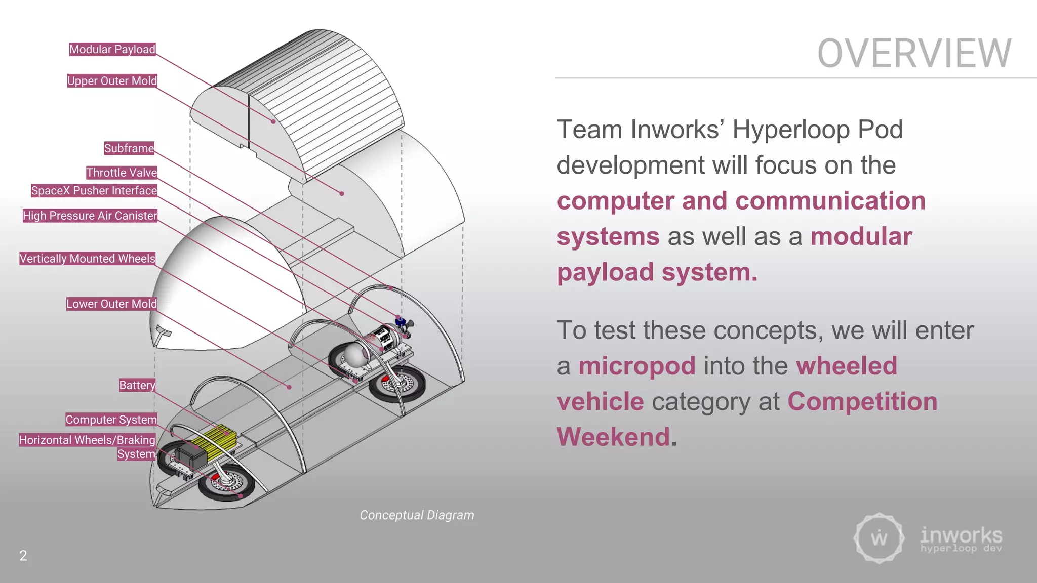
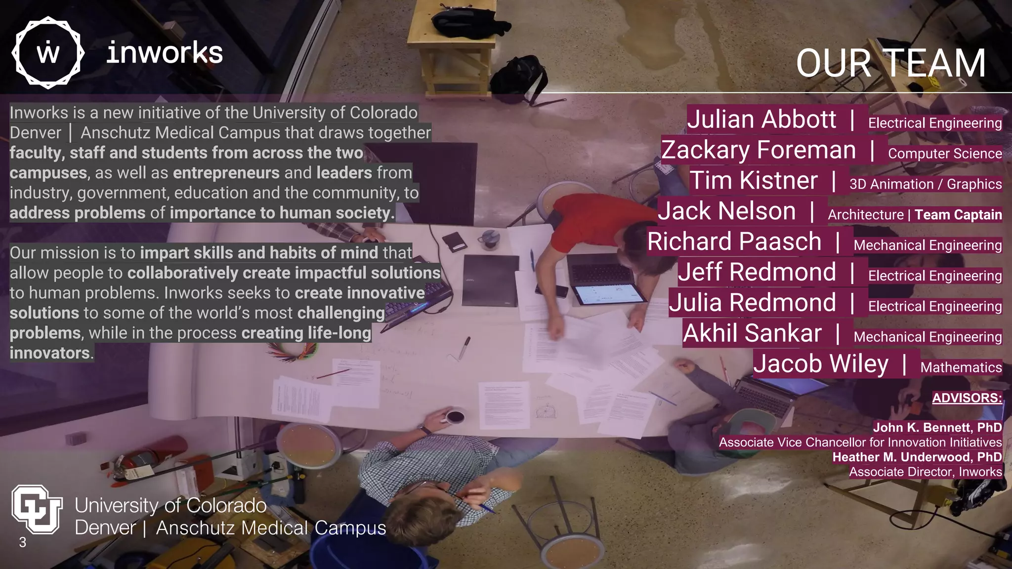
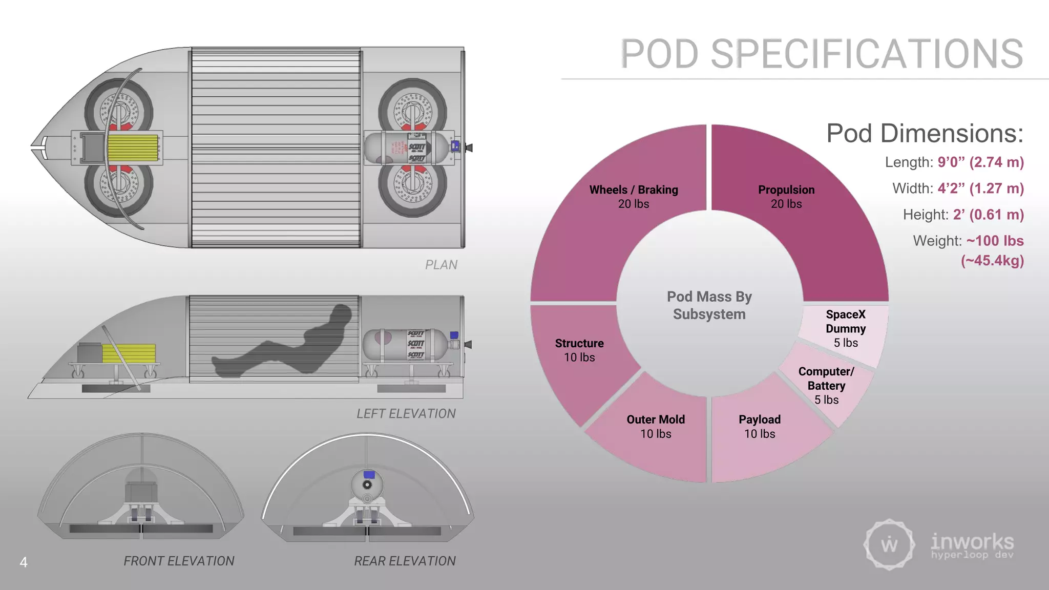
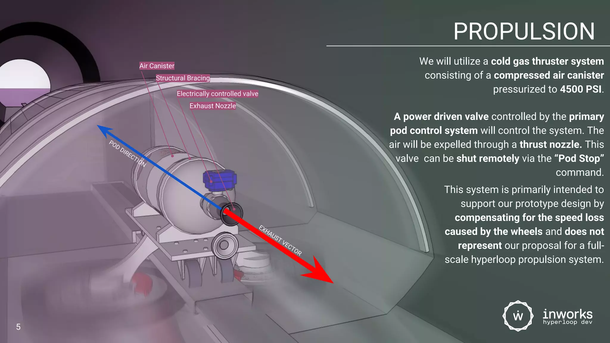
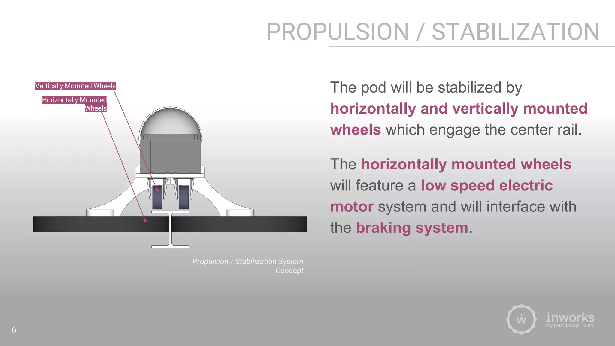
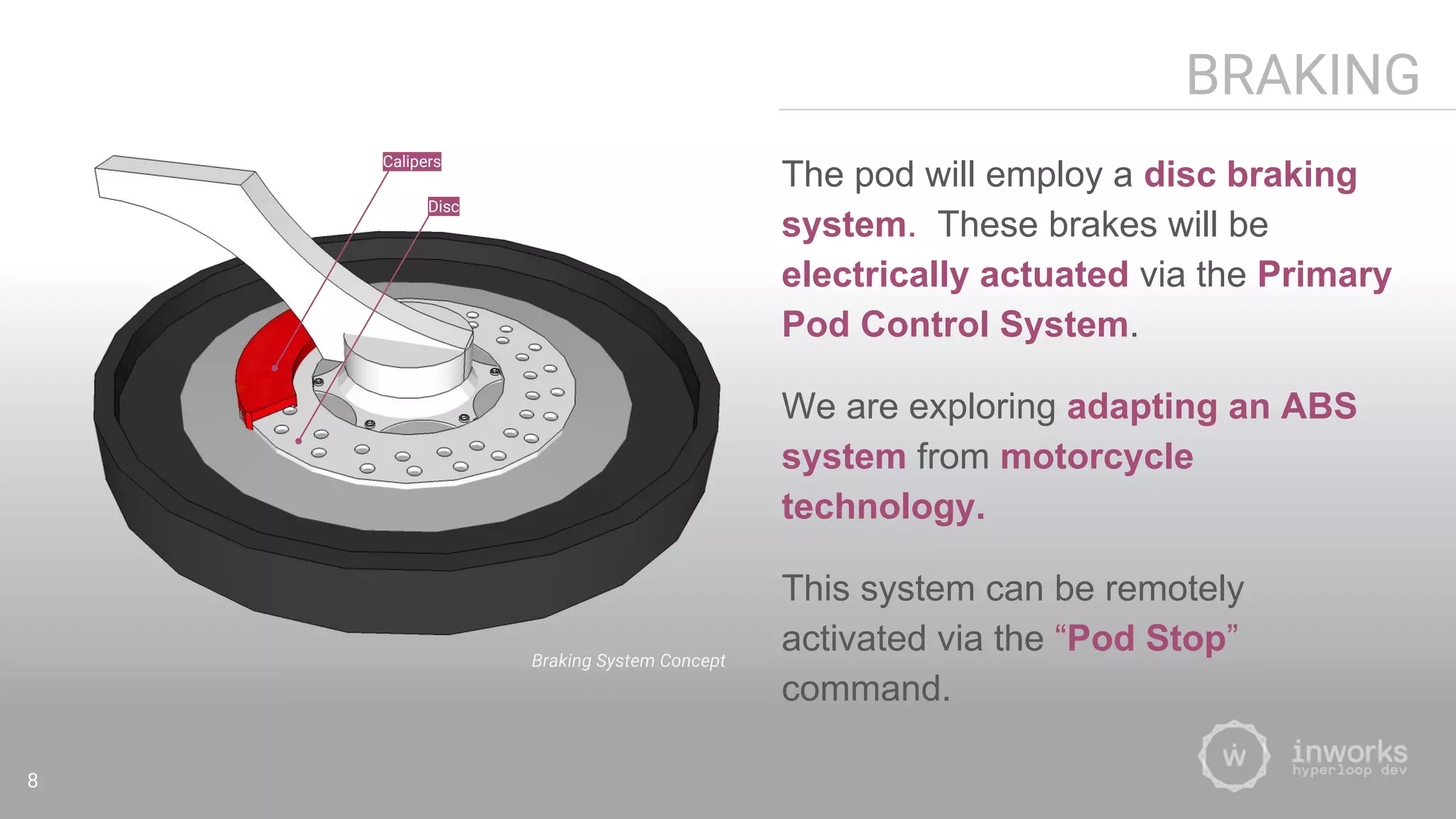
OVERVIEW
Team Inworks’ Hyperloop Pod
development will focus on the
computer and communication
systems as well as a modular
payload system.
To test these concepts, we will enter
a micropod into the wheeled
vehicle category at Competition
Weekend.
Conceptual Diagram
Upper Outer Mold
Subframe
Throttle Valve
High Pressure Air Canister
Vertically Mounted Wheels
Lower Outer Mold
Battery
Computer System
Horizontal Wheels/Braking
System
2
SpaceX Pusher Interface
Modular Payload
OUR TEAM
Julian Abbott | Electrical Engineering
Zackary Foreman | Computer Science
Tim Kistner | 3D Animation / Graphics
Jack Nelson | Architecture | Team Captain
Richard Paasch | Mechanical Engineering
Jeff Redmond | Electrical Engineering
Julia Redmond | Electrical Engineering
Akhil Sankar | Mechanical Engineering
Jacob Wiley | Mathematics
Inworks is a new initiative of the University of Colorado
Denver │ Anschutz Medical Campus that draws together
faculty, staff and students from across the two
campuses, as well as entrepreneurs and leaders from
industry, government, education and the community, to
address problems of importance to human society.
Our mission is to impart skills and habits of mind that
allow people to collaboratively create impactful solutions
to human problems. Inworks seeks to create innovative
solutions to some of the world’s most challenging
problems, while in the process creating life-long
innovators.
ADVISORS:
John K. Bennett, PhD
Associate Vice Chancellor for Innovation Initiatives
Heather M. Underwood, PhD
Associate Director, Inworks
3
POD SPECIFICATIONS
Pod Dimensions:
Length: 9’0” (2.74 m)
Width: 4’2” (1.27 m)
Height: 2’ (0.61 m)
Weight: ~100 lbs
(~45.4kg)PLAN
4
Propulsion
20 lbs
Wheels / Braking
20 lbs
Structure
10 lbs
Pod Mass By
Subsystem
Outer Mold
10 lbs
Payload
10 lbs
Computer/
Battery
5 lbs
LEFT ELEVATION
FRONT ELEVATION
SpaceX
Dummy
5 lbs
REAR ELEVATION
PROPULSION
We will utilize a cold gas thruster system
consisting of a compressed air canister
pressurized to 4500 PSI.
A power driven valve controlled by the primary
pod control system will control the system. The
air will be expelled through a thrust nozzle. This
valve can be shut remotely via the “Pod Stop”
command.
5
Exhaust Nozzle
Electrically controlled valve
Structural Bracing
Air Canister
EXHAUST VECTOR
POD
DIRECTION
This system is primarily intended to
support our prototype design by
compensating for the speed loss
caused by the wheels and does not
represent our proposal for a full-
scale hyperloop propulsion system.
PROPULSION / STABILIZATION
The pod will be stabilized by
horizontally and vertically mounted
wheels which engage the center rail.
The horizontally mounted wheels
will feature a low speed electric
motor system and will interface with
the braking system.
Propulsion / Stabilization System
Concept
Vertically Mounted Wheels
Horizontally Mounted
Wheels
6
NAVIGATION
The Primary Pod Control
System will control the
navigation system. A triple-axis
digital output gyroscope with
built-in accelerometer will
monitor velocity, pitch, yaw, and
roll.
Self-contained, full-spectrum
photoelectric sensors mounted
on the front of the pod will
establish location by detecting
change in appearance of the
linear distance markers.
7
BRAKING
The pod will employ a disc braking
system. These brakes will be
electrically actuated via the Primary
Pod Control System.
We are exploring adapting an ABS
system from motorcycle
technology.
This system can be remotely
activated via the “Pod Stop”
command.
Braking System Concept
8
Calipers
Disc
LEVITATION
The current design will not feature
levitation.
Depending on availability of funding
following Design Weekend, we will
conduct a cost benefit analysis and
research air bearing and magnetic
levitation technologies.
Possible Air Bearing and Maglev
Designs
9
COMPUTER SYSTEM OVERVIEW
The embedded computer system will
continuously assess, manage, and
adjust the status of the pod and provide
external communications capabilities.
Computer System Top Level Diagram
10
External
Control
System
Primary Pod
Control System
Secondary Pod
Control System
POD CONTROL SYSTEMThe Primary and Secondary Control System will
provide logical operations to the hyperloop pod.
The Primary will act as the main driver for system
controls while the Secondary will serve as a
redundancy to the Primary.
11
Drive Control
Power Electronics
Body control
Brake Systems
Propulsion System
Wheel System
Control System,
Feedback &
Monitoring
Accelerometer
Gyroscopes
Excess Heat
Proximity Sensors
Instrument cluster
Operator touch Screen
Telemetry Devices
Power Control
Power Storage / Distribution
Battery Recharge
HVAC
Pod Control
System
Emergency Shutdown
Command
Navigation &
Communication
General Navigation
Positioning
Network Communication CISCO
IW3700
MICROPROCESSOR INTERFACES
Microprocessor / Peripheral Interface
12
Servo Ports
Braking, air actuation
Serial Ports
Electric motor control
Switching Regulator
Circuit
Absolute Pressure
Differential Pressure
Temperature Sensors
Stereo Vision
Power Port
Proximity Sensors
Rate Gyros
Processor
ADC
Analog/Digital Converter
ADC
Analog/Digital Converter
Accelerometers
REAL TIME OPERATING SYSTEM
All embedded system architecture for
the unmanned pod will be run through a
Real Time Operating System (RTOS)
for unified computing and analysis.
The inherently faster processing
capability that an RTOS provides
allows rapid detection of emergency
situations by reducing latency.
13
RTOS Overview
MODULAR PAYLOAD
The middle section of our pod will
accommodate a modular payload
system.
A modular payload system in a full scale
hyperloop design will significantly
reduce the cost of construction and
operation of the pods, support multiple
configurations, control weight
distribution, and allow rapid turnaround
of the pods at the station.Modular Payload Concept
14
MODULAR PAYLOAD
The modules would be designed to support multiple configurations and a variety of user types.
15
Single Person / ADA Sleeper Two Person Group / Family / Economy Cargo / Luggage / Freight
Controlling the arrangement of the modules will allow for optimization of weight distribution
according to the loads, improving the pod’s overall stability and performance.
MODULAR PAYLOAD
A modular payload system would drastically improve
turnaround time once a hyperloop pod arrives at the station.
This would reduce the number of pods required in
circulation in order to maintain the operating schedule
of the route, thereby reducing overall cost.
16
These modules would also optimize maintenance and upkeep of the
system by allowing time for the modules to be maintained between
use in the system while keeping all pods in circulation.
MODULAR PAYLOAD
The sleeper modules could be used within the station to provide inexpensive lodging
to travelers. This would encourage more frequent travel by providing lodging at a price
point comparable to the low price of the hyperloop ticket.
17
POWER
18
Power distribution will provide power to onboard
electronics by utilizing common Electrical and
Electronic System Architecture with an
Integrated Electrical Distribution System.
The Primary Power System will efficiently
manage and distribute power among known
supplies.
The Emergency Power System will consist of
backup lithium ion battery packs in case of total
power loss.
24v
Photoelectric
Sensor
24v
Propulsion
Actuator
24v
Braking
Control
24v
Electric
Motors
24v
Wireless Access
Point
5v Proximity Sensor
5v Accelerometer
5v Gyroscope3.5v Pressure / Temp
Electrical
Loads by
Subsystem
HAZMAT / STORED ENERGY
The lithium contained within the battery will be the only hazardous material / stored energy onboard the
pod.
19
SAFETY FEATURES
A remotely activated “Pod Stop”
command may be sent to the pod in
case of emergency.
Pod Stop will place the pod in a safe
condition by shutting the air canister
valve to slow propulsion and
engaging the braking systems.
Pod Stop Command Actions
20
POD STOP
COMMAND ISSUED
SHUT COMMAND
TO AIR ACTUATION
VALVE
BRAKE SYSTEM
ENGAGE
COMMAND
SYSTEM PLACED IN
STANDBY TO AWAIT
FURTHER COMMANDS
Thank you.

Team Inworks Hyperloop Pod Preliminary Design

  • 2.
    OVERVIEW Team Inworks’ HyperloopPod development will focus on the computer and communication systems as well as a modular payload system. To test these concepts, we will enter a micropod into the wheeled vehicle category at Competition Weekend. Conceptual Diagram Upper Outer Mold Subframe Throttle Valve High Pressure Air Canister Vertically Mounted Wheels Lower Outer Mold Battery Computer System Horizontal Wheels/Braking System 2 SpaceX Pusher Interface Modular Payload
  • 3.
    OUR TEAM Julian Abbott| Electrical Engineering Zackary Foreman | Computer Science Tim Kistner | 3D Animation / Graphics Jack Nelson | Architecture | Team Captain Richard Paasch | Mechanical Engineering Jeff Redmond | Electrical Engineering Julia Redmond | Electrical Engineering Akhil Sankar | Mechanical Engineering Jacob Wiley | Mathematics Inworks is a new initiative of the University of Colorado Denver │ Anschutz Medical Campus that draws together faculty, staff and students from across the two campuses, as well as entrepreneurs and leaders from industry, government, education and the community, to address problems of importance to human society. Our mission is to impart skills and habits of mind that allow people to collaboratively create impactful solutions to human problems. Inworks seeks to create innovative solutions to some of the world’s most challenging problems, while in the process creating life-long innovators. ADVISORS: John K. Bennett, PhD Associate Vice Chancellor for Innovation Initiatives Heather M. Underwood, PhD Associate Director, Inworks 3
  • 4.
    POD SPECIFICATIONS Pod Dimensions: Length:9’0” (2.74 m) Width: 4’2” (1.27 m) Height: 2’ (0.61 m) Weight: ~100 lbs (~45.4kg)PLAN 4 Propulsion 20 lbs Wheels / Braking 20 lbs Structure 10 lbs Pod Mass By Subsystem Outer Mold 10 lbs Payload 10 lbs Computer/ Battery 5 lbs LEFT ELEVATION FRONT ELEVATION SpaceX Dummy 5 lbs REAR ELEVATION
  • 5.
    PROPULSION We will utilizea cold gas thruster system consisting of a compressed air canister pressurized to 4500 PSI. A power driven valve controlled by the primary pod control system will control the system. The air will be expelled through a thrust nozzle. This valve can be shut remotely via the “Pod Stop” command. 5 Exhaust Nozzle Electrically controlled valve Structural Bracing Air Canister EXHAUST VECTOR POD DIRECTION This system is primarily intended to support our prototype design by compensating for the speed loss caused by the wheels and does not represent our proposal for a full- scale hyperloop propulsion system.
  • 6.
    PROPULSION / STABILIZATION Thepod will be stabilized by horizontally and vertically mounted wheels which engage the center rail. The horizontally mounted wheels will feature a low speed electric motor system and will interface with the braking system. Propulsion / Stabilization System Concept Vertically Mounted Wheels Horizontally Mounted Wheels 6
  • 7.
    NAVIGATION The Primary PodControl System will control the navigation system. A triple-axis digital output gyroscope with built-in accelerometer will monitor velocity, pitch, yaw, and roll. Self-contained, full-spectrum photoelectric sensors mounted on the front of the pod will establish location by detecting change in appearance of the linear distance markers. 7
  • 8.
    BRAKING The pod willemploy a disc braking system. These brakes will be electrically actuated via the Primary Pod Control System. We are exploring adapting an ABS system from motorcycle technology. This system can be remotely activated via the “Pod Stop” command. Braking System Concept 8 Calipers Disc
  • 9.
    LEVITATION The current designwill not feature levitation. Depending on availability of funding following Design Weekend, we will conduct a cost benefit analysis and research air bearing and magnetic levitation technologies. Possible Air Bearing and Maglev Designs 9
  • 10.
    COMPUTER SYSTEM OVERVIEW Theembedded computer system will continuously assess, manage, and adjust the status of the pod and provide external communications capabilities. Computer System Top Level Diagram 10 External Control System Primary Pod Control System Secondary Pod Control System
  • 11.
    POD CONTROL SYSTEMThePrimary and Secondary Control System will provide logical operations to the hyperloop pod. The Primary will act as the main driver for system controls while the Secondary will serve as a redundancy to the Primary. 11 Drive Control Power Electronics Body control Brake Systems Propulsion System Wheel System Control System, Feedback & Monitoring Accelerometer Gyroscopes Excess Heat Proximity Sensors Instrument cluster Operator touch Screen Telemetry Devices Power Control Power Storage / Distribution Battery Recharge HVAC Pod Control System Emergency Shutdown Command Navigation & Communication General Navigation Positioning Network Communication CISCO IW3700
  • 12.
    MICROPROCESSOR INTERFACES Microprocessor /Peripheral Interface 12 Servo Ports Braking, air actuation Serial Ports Electric motor control Switching Regulator Circuit Absolute Pressure Differential Pressure Temperature Sensors Stereo Vision Power Port Proximity Sensors Rate Gyros Processor ADC Analog/Digital Converter ADC Analog/Digital Converter Accelerometers
  • 13.
    REAL TIME OPERATINGSYSTEM All embedded system architecture for the unmanned pod will be run through a Real Time Operating System (RTOS) for unified computing and analysis. The inherently faster processing capability that an RTOS provides allows rapid detection of emergency situations by reducing latency. 13 RTOS Overview
  • 14.
    MODULAR PAYLOAD The middlesection of our pod will accommodate a modular payload system. A modular payload system in a full scale hyperloop design will significantly reduce the cost of construction and operation of the pods, support multiple configurations, control weight distribution, and allow rapid turnaround of the pods at the station.Modular Payload Concept 14
  • 15.
    MODULAR PAYLOAD The moduleswould be designed to support multiple configurations and a variety of user types. 15 Single Person / ADA Sleeper Two Person Group / Family / Economy Cargo / Luggage / Freight Controlling the arrangement of the modules will allow for optimization of weight distribution according to the loads, improving the pod’s overall stability and performance.
  • 16.
    MODULAR PAYLOAD A modularpayload system would drastically improve turnaround time once a hyperloop pod arrives at the station. This would reduce the number of pods required in circulation in order to maintain the operating schedule of the route, thereby reducing overall cost. 16 These modules would also optimize maintenance and upkeep of the system by allowing time for the modules to be maintained between use in the system while keeping all pods in circulation.
  • 17.
    MODULAR PAYLOAD The sleepermodules could be used within the station to provide inexpensive lodging to travelers. This would encourage more frequent travel by providing lodging at a price point comparable to the low price of the hyperloop ticket. 17
  • 18.
    POWER 18 Power distribution willprovide power to onboard electronics by utilizing common Electrical and Electronic System Architecture with an Integrated Electrical Distribution System. The Primary Power System will efficiently manage and distribute power among known supplies. The Emergency Power System will consist of backup lithium ion battery packs in case of total power loss. 24v Photoelectric Sensor 24v Propulsion Actuator 24v Braking Control 24v Electric Motors 24v Wireless Access Point 5v Proximity Sensor 5v Accelerometer 5v Gyroscope3.5v Pressure / Temp Electrical Loads by Subsystem
  • 19.
    HAZMAT / STOREDENERGY The lithium contained within the battery will be the only hazardous material / stored energy onboard the pod. 19
  • 20.
    SAFETY FEATURES A remotelyactivated “Pod Stop” command may be sent to the pod in case of emergency. Pod Stop will place the pod in a safe condition by shutting the air canister valve to slow propulsion and engaging the braking systems. Pod Stop Command Actions 20 POD STOP COMMAND ISSUED SHUT COMMAND TO AIR ACTUATION VALVE BRAKE SYSTEM ENGAGE COMMAND SYSTEM PLACED IN STANDBY TO AWAIT FURTHER COMMANDS
  • 21.