SlideShare a Scribd company logo
1 of 68
Download to read offline
Air breaking system using exhaust gas
ME DEPARTMENT FGIET
1
Air breaking system using Engine exhaust gas
Submitted in partial fulfillment of the requirements for the
award of degree of
BACHELOR OF TECHNOLOGY
IN
Mechanical ENGINEERING
Submitted By:
Student name Roll No
College Logo
College Name
SUBMITTED TO: …………………………
Air breaking system using exhaust gas
ME DEPARTMENT FGIET
2
Contents
ABSTRACT.................................................................................................................................... 6
INTRODUCTION .......................................................................................................................... 6
LITERATURE SURVEY............................................................................................................... 8
DESCRIPTION OF EQUIPMENTS ............................................................................................ 20
Engine ........................................................................................................................................... 24
Carburetor ..................................................................................................................................... 24
WORKING ................................................................................................................................... 25
Hardware used: ............................................................................................................................. 25
CONCLUSIONS........................................................................................................................... 64
REFERENCES ............................................................................................................................. 67
Air breaking system using exhaust gas
ME DEPARTMENT FGIET
3
DECLARATION
I hereby declare that the project report entitled “Android based all-purpose agriculture
machine” submitted is our original work and the report has not formed the basis for the award of
any degree, associate ship, fellowship or any other similar title.
Signature:
Name:
Air breaking system using exhaust gas
ME DEPARTMENT FGIET
4
CERTIFICATE
This is to certify that the project report entitled “Android based all-purpose agriculture
machine” is the bona fide work carried out by students of “College Name” during the year 2016
in partial fulfillment of the requirements for the award of the Degree of B. Tech. The report has
not formed the basis for the award previously of any degree, diploma, associate ship, fellowship
or any other similar title.
Signature of the guide:
Date:
Air breaking system using exhaust gas
ME DEPARTMENT FGIET
5
ACKNOWLEDGEMENT
It gives me great pleasure to express my gratitude and heart full thanks to all those who are
helping me in complete this project.
I want to thank to “guide name”, who has always encouraged and help me in making
this project. In addition to this, I am grateful to other faculties too who made me in right
direction and gave me their precious time and expert guidance whenever necessary through
which I could achieve this extent.
At last but not the least I am feeling glad to say about my family whose wishes are
always with me, without which it was not possible for me to reach this extent.
I hope my work is praised and my efforts render fruitful result.
THANK YOU
Signature:
Name:
Air breaking system using exhaust gas
ME DEPARTMENT FGIET
6
ABSTRACT
The aim is to design and to develop an air brake system based on exhaust gas is called
“fabrication of air brake system using engine exhaust gas”. The main aim of this project is to
reduce the workloads of the engine drive to operate the air compressor, because here the
compressor is not operated by the engine drive.
Here we are placing a turbine in the path of exhaust from the engine. The turbine e is
connected to a dynamo by means of coupling, which is used to generate power. Depending upon
the airflow the turbine will start rotating, and then the dynamo will also starts to rotate. A
dynamo is a device which is used to convert the kinetic energy into electrical energy. The
generated power can be stored in the battery and then this electric power has loaded to the D.C
compressor. The air compressor compresses the atmospheric air and it stored in the air tank and
the air tank has pressure relief valve to control the pressure in the tank . The air tank supplies the
compressed pneumatic power to the pneumatic actuator through solenoid valve to apply brake.
The pneumatic actuator is a double acting cylinder which converts hydraulic energy into linear
moti on.
Air breaking system using exhaust gas
ME DEPARTMENT FGIET
7
Chapter 1
INTRODUCTION
Air breaking system using exhaust gas
ME DEPARTMENT FGIET
8
INTRODUCTION
We waste so much energy. As much as 60 percent of energy is wasted as heat. Our
laptops, nuclear power plants, chemical factories and cars all contribute to this waste heat.
Researchers at Purdue University are working with General Motors to create thermoelectric
generators (TEGs) to turn waste heat directly into electrical energy for cars. The idea is to use
the heat from the car engine’s exhaust to generate electricity. The prototype which is a small
metal chip will basically hook up to the exhaust system and tap into heat coming from the
gases . The technology used today can’t hold up against the high temperatures inside catalytic
converters. But the material the researchers want to use is called skutterudite, which is a mix of
minerals. Then other rare metals are added to it to make sure it’s a poor conductor. That way,
the current is generated when the material is hot on one side and cold on the other. Ideally, it
would reduce the amount of fuel used by five percent. It does this as it generates electricity to
help power the car’s electrical sy stem and charge its battery. The applications of the
technology go beyond car exhaust. It could generate electricity in homes and power plants
from waste streams. Waste byproducts could supply 19 percent of U.S. power, the heat sure
gets lost easily. The promise is there, but the technical hurdles remain.
BRAKING SYSTEM
A brake is a mechanical device that inhibits motion by absorbing energy from a moving
system It is used for slowing or stopping a moving vehicle, wheel, axle, or to prevent its motion,
most often accomplished by means of friction.
Most brakes commonly use friction between two surfaces pressed together to convert the kinetic
energy of the moving object into heat, though other methods of energy conversion may be
employed. For example, regenerative braking converts much of the energy to electrical energy.
which may be stored for later use. Other methods convert kinetic energy into potential energy in
such stored forms as pressurized air or pressurized oil. Eddy current brakes use magnetic fields
to convert kinetic energy into electric current in the brake disc, fin, or rail, which is converted
into heat. Still other braking methods even transform kinetic energy into different forms, for
example by transferring the energy to a rotating flywheel.
Air breaking system using exhaust gas
ME DEPARTMENT FGIET
9
Brakes are generally applied to rotating axles or wheels, but may also take other forms such as
the surface of a moving fluid (flaps deployed into water or air). Some vehicles use a combination
of braking mechanisms, such as drag racing cars with both wheel brakes and a parachute, or
airplanes with both wheel brakes and drag flaps raised into the air during landing.
Friction brakes on automobiles store braking heat in the drum brake or disc brake while braking
then conduct it to the air gradually. When traveling downhill some vehicles can use their engines
to brake.
When the brake pedal of a modern vehicle with hydraulic brakes is pushed against the master
cylinder, ultimately a piston pushes the brake pad against the brake disc which slows the wheel
down. On the brake drum it is similar as the cylinder pushes the brake shoes against the drum
which also slows the wheel down.
TYPES
Brakes may be broadly described as using friction, pumping, or electromagnetics. One brake
may use several principles: for example, a pump may pass fluid through an orifice to create
friction:
Frictional
Frictional brakes are most common and can be divided broadly into "shoe" or "pad" brakes,
using an explicit wear surface, and hydrodynamic brakes, such as parachutes, which use friction
in a working fluid and do not explicitly wear. Typically the term "friction brake" is used to mean
pad/shoe brakes and excludes hydrodynamic brakes, even though hydrodynamic brakes use
friction. Friction (pad/shoe) brakes are often rotating devices with a stationary pad and a rotating
wear surface. Common configurations include shoes that contract to rub on the outside of a
rotating drum, such as a band brake; a rotating drum with shoes that expand to rub the inside of a
drum, commonly called a "drum brake", although other drum configurations are possible; and
pads that pinch a rotating disc, commonly called a "disc brake". Other brake configurations are
Air breaking system using exhaust gas
ME DEPARTMENT FGIET
10
used, but less often. For example, PCC trolley brakes include a flat shoe which is clamped to the
rail with an electromagnet; the Murphy brake pinches a rotating drum, and the Ausco Lambert
disc brake uses a hollow disc (two parallel discs with a structural bridge) with shoes that sit
between the disc surfaces and expand laterally.
A drum brake is a vehicle brake in which the friction is caused by a set of brake shoes that press
against the inner surface of a rotating drum. The drum is connected to the rotating roadwheel
hub.
Drum brakes generally can be found on older car and truck models. However, because of their
low production cost, drum brake setups are also installed on the rear of some low-cost newer
vehicles. Compared to modern disc brakes, drum brakes wear out faster due to their tendency to
overheat.
The disc brake is a device for slowing or stopping the rotation of a road wheel. A brake disc (or
rotor in U.S. English), usually made of cast iron or ceramic, is connected to the wheel or the
axle. To stop the wheel, friction material in the form of brake pads (mounted in a device called
a brake caliper) is
forced mechanically, hydraulically, pneumatically or electromagnetically against both sides of
the disc. Friction causes the disc and attached wheel to slow or stop.
Ceramic brakes,[3] also called "carbon ceramic", are high-end type of frictional brakes with brake
pads and rotors made from porcelain compound blends, that feature better stopping capability
and greater resistance to overheat. Due to their high production cost, ceramic brakes aren't
Air breaking system using exhaust gas
ME DEPARTMENT FGIET
11
widely used as factory equipment, and their availability on the automotive aftermarket is low
compared to traditional metallic brakes. However, being performance-oriented equipment,
ceramic brakes are popular among racers
Pumping
Pumping brakes are often used where a pump is already part of the machinery. For example, an
internal-combustion piston motor can have the fuel supply stopped, and then internal pumping
losses of the engine create some braking. Some engines use a valve override called a Jake
brake to greatly increase pumping losses. Pumping brakes can dump energy as heat, or can be
regenerative brakes that recharge a pressure reservoir called a hydraulic accumulator.
Electromagnetic
Electromagnetic brakes are likewise often used where an electric motor is already part of the
machinery. For example, many hybrid gasoline/electric vehicles use the electric motor as a
generator to charge electric batteries and also as a regenerative brake. Some diesel/electric
railroad locomotives use the electric motors to generate electricity which is then sent to a resistor
bank and dumped as heat. Some vehicles, such as some transit buses, do not already have an
electric motor but use a secondary "retarder" brake that is effectively a generator with an internal
short-circuit. Related types of such a brake are eddy current brakes, and electro-mechanical
brakes (which actually are magnetically driven friction brakes, but nowadays are often just called
"electromagnetic brakes" as well).
Air breaking system using exhaust gas
ME DEPARTMENT FGIET
12
Electromagnetic brakes slow an object through electromagnetic induction, which
creates resistance and in turn either heat or electricity. Friction brakes apply pressure on two
separate objects to slow the vehicle in a controlled manner.
AIR BRAKES
CHARACTERISTICS
Brakes are often described according to several characteristics including:
Air breaking system using exhaust gas
ME DEPARTMENT FGIET
13
 Peak force – The peak force is the maximum decelerating effect that can be obtained. The
peak force is often greater than the traction limit of the tires, in which case the brake can
cause a wheel skid.
 Continuous power dissipation – Brakes typically get hot in use, and fail when the
temperature gets too high. The greatest amount of power (energy per unit time) that can be
dissipated through the brake without failure is the continuous power dissipation. Continuous
power dissipation often depends on e.g., the temperature and speed of ambient cooling air.
 Fade – As a brake heats, it may become less effective, called brake fade. Some designs are
inherently prone to fade, while other designs are relatively immune. Further, use
considerations, such as cooling, often have a big effect on fade.
 Smoothness – A brake that is grabby, pulses, has chatter, or otherwise exerts varying brake
force may lead to skids. For example, railroad wheels have little traction, and friction brakes
without an anti-skid mechanism often lead to skids, which increases maintenance costs and
leads to a "thump thump" feeling for riders inside.
 Power – Brakes are often described as "powerful" when a small human application force
leads to a braking force that is higher than typical for other brakes in the same class. This
notion of "powerful" does not relate to continuous power dissipation, and may be confusing
in that a brake may be "powerful" and brake strongly with a gentle brake application, yet
have lower (worse) peak force than a less "powerful" brake.
 Pedal feel – Brake pedal feel encompasses subjective perception of brake power output as a
function of pedal travel. Pedal travel is influenced by the fluid displacement of the brake and
other factors.
 Drag – Brakes have varied amount of drag in the off-brake condition depending on design of
the system to accommodate total system compliance and deformation that exists under
braking with ability to retract friction material from the rubbing surface in the off-brake
condition.
 Durability – Friction brakes have wear surfaces that must be renewed periodically. Wear
surfaces include the brake shoes or pads, and also the brake disc or drum. There may be
tradeoffs, for example a wear surface that generates high peak force may also wear quickly.
 Weight – Brakes are often "added weight" in that they serve no other function. Further,
brakes are often mounted on wheels, and unsprung weight can significantly hurt traction in
Air breaking system using exhaust gas
ME DEPARTMENT FGIET
14
some circumstances. "Weight" may mean the brake itself, or may include additional support
structure.
 Noise – Brakes usually create some minor noise when applied, but often create squeal or
grinding noises that are quite loud.
AIR BREAK
An air brake or, more formally, a compressed air brake system, is a type of friction brake for
vehicles in which compressed air pressing on a piston is used to apply the pressure to the brake
pad needed to stop the vehicle. Air brakes are used in large heavy vehicles, particularly those
having multiple trailers which must be linked into the brake system, such
as trucks, buses, trailers, and semi-trailers in addition to their use in railroad trains. George
Westinghouse first developed air brakes for use in railway service. He patented a safer air brake
on March 5, 1872. Westinghouse made numerous alterations to improve his air pressured brake
invention, which led to various forms of the automatic brake. In the early 20th century, after its
advantages were proven in railway use, it was adopted by manufacturers of trucks and
heavy road vehicles.
DESIGN AND FUNCTION
Air brake systems are typically used on heavy trucks and buses. The system consists of service
brakes, parking brakes, a control pedal, and an air storage tank. For the parking brake, there's
a disc or drum brake arrangement which is designed to be held in the 'applied' position by spring
pressure. Air pressure must be produced to release these "spring brake" parking brakes. For the
service brakes (the ones used while driving for slowing or stopping) to be applied, the brake
pedal is pushed, routing the air under pressure (approx 100–120 psi or 690–830 kPa or 6.89-8.27
bar) to the brake chamber, causing the brake to be engaged. Most types of truck air brakes are
drum brakes, though there is an increasing trend towards the use of disc brakes in this
application. The air compressor draws filtered air from the atmosphere and forces it into high-
pressure reservoirs at around 120 psi (830 kPa; 8.3 bar). Most heavy vehicles have a gauge
within the driver's view, indicating the availability of air pressure for safe vehicle operation,
often including warning tones or lights. A mechanical "wig wag" that automatically drops down
Air breaking system using exhaust gas
ME DEPARTMENT FGIET
15
into the driver's field of vision when the pressure drops below a certain point is also common.
Setting of the parking/emergency brake releases the pressurized air in the lines between the
compressed air storage tank and the brakes, thus allowing the spring actuated parking brake to
engage. A sudden loss of air pressure would result in full spring brake pressure immediately.
A compressed air brake system is divided into a supply system and a control system. The supply
system compresses, stores and supplies high-pressure air to the control system as well as to
additional air operated auxiliary truck systems (gearbox shift control, clutch pedal air
assistance servo, etc.).
A Purdue University team, in collaboration with General Motors, is setting out to
develop a new type of thermoelectric generator that can convert heat from a car's exhaust into
electricity. The first prototype of the energy saving technology could reduce fuel consumption
by 5 to 10 percent. The idea is to place a device built from thermoelectric materials (materials
that can generate an electrical current from temperature differences) in the exhaust system
behind the catalytic converter, where heat from gas ses can reach temperatures nearing 1,000
degrees Celsius. That heat could then be converted into electricity by the thermoelectric
materials. "The material is hot on the side facing the exhaust gases and cool on the other side,
and this difference must be maintained to continually generate a current", said Xianfan Xu, a
Purdue professor working on the project. One obstacle that has prevented technology like this
from succeeding before is that current thermoelectric material cannot withstand the sweltering
temperatures inside catalytic converters. That's what the Purdue team aims to remedy. For
instance, the first prototype can harvest heat from gasses that are about 700 degrees Celsius.
"The biggest challenge is system
level design how to optimize everything to get as much heat as possible from the exhaust gas",
Xu said. "The engine exhaust has to lose as much heat as possible to the material".
The electricity generated from the exhaust could then help power a car's electrical
systems, reducing strain on the engine and ultimately improving fuel economy. Helping your
auto to puff-puff along more efficiently is only the start of what this new technology could
achieve, however. Thermoelectric technologies can also be used for other applications such as
harnessing waste heat to generate electricity in homes and power plants. They might even lead
to the development of a new type of solar cell or a solid -state refrigerator, said Xu
Air breaking system using exhaust gas
ME DEPARTMENT FGIET
16
Chapter 2
LITERATURE
SURVEY
Air breaking system using exhaust gas
ME DEPARTMENT FGIET
17
LITERATURE SURVEY
The various research works attempted in the area of energy conservation and specifically in the
area of air compressor and pneumatic systems have been referred and discussed here.
 According to John (1995), the opportunities for cost savings in compressed air supply
system includes but not limited to waste heat recovery, compressed air leakage reduction,
use of outside air for compressor, compressor control, air pressure control, compressor
selection and usage of IC engine for compressor driving.
 The solution for compressed air leaks is to make leak finding and correcting as a part of
the normal maintenance process and repeating leak survey at least once a year (John
Holdsworth 1997). Over-pressurization can also result from short sighted selection of
ancillary equipments. Bill Howe and Bill Scales (1998) report that the opportunities for
improved compressed air efficiency where air is used internally, but uneconomically are
less understood. Supplying air at required pressure, appropriate use of air, automated
controls are some of the recommendations given by the authors.
Air breaking system using exhaust gas
ME DEPARTMENT FGIET
18
 Cost effective efficiency opportunities in production and usage of compressed air are
often ignored by the industries due to various reasons and selection of correct compressor
control also plays a major role in the energy consumption by the air compressors (Robert
1999). Leaks, inappropriate usage of compressed air, poor selection of compressors and
ancillary equipments, pressure problem and poor attempts to solve these problems are
some other common causes of inefficiency in the compressor system.
 According to David (1999), estimates and actual measurements of compressed air
systems show that 10 % to 35% air is lost due to leak or improper use. Proper
maintenance, sound design and appropriate usage of the compressed air can contribute
for energy savings.
 Durmus Kaya et al (2002) attempted energy conservation with repairing air leaks,
installing high efficiency motors, reducing the average air inlet temperature by using
outside air and reducing compressor air pressure. The pay back periods for the
investments made with these measures were very less. Proper maintenance and
appropriate use of compressed air can contribute to cost effective and energy efficient
compressed air system, along with the control mode (U.S 2003). Different efficiencies
are considered for performance evaluation of compressors (Ueno et al 2003).
 Maintenance, monitoring, blocking leakage, minimising air inlet temperature, minimising
allowable pressure dew point at air intake, controls, properly sized pipes, heat recovery,
usage of natural gas engine for driving air compressor, system improvement and
improvement in the motor are the options described by Christina et al (2003). Asfaw
(2005), lists leak and air supply at higher pressure than required are the major causes
besides over sized compressors, running compressors when not needed, wrong
application of compressed air etc.
 Studies on energy conservation in compressors and pneumatic systems
 Several attempts have been made already, to optimise compressor and its accessories as
well as pneumatic systems so as to reduce the energy consumption. Fujiwara and Osada
(1995) used computer simulation for analysing the performance of the screw
compressors. Computer based tools are also developed for identifying energy saving
Air breaking system using exhaust gas
ME DEPARTMENT FGIET
19
opportunities in industries, compressed air system is one of its application areas
(Gopalakrishnan et al 1997). Pascal et al (2001) propose a global model for the
thermodynamic analysis of reciprocating air compressor based on five main and four
secondary dimensionless parameters used to predict the performance of a reciprocating
air compressor under various operating conditions.
 Exergy analysis as a tool was used for the design, optimization, and performance
evaluation of energy systems (Recep et al 2002). Kagawa et al also used exergy approach
for the energy assessment of pneumatic cylinder actuation system and reported that the
approach is effective on clarifying the energy distribution in pneumatic cylinders.
Attempts had been made to 23 optimise screw compressors during the design stage itself
(Stosic et al 2003). Jiang et al (2003) used an integrated CAD/CAM method for design
and manufacturing of scroll compressors
Keeping the above in consideration, the scope of this project has the following
OBJECTIVES:
i) To suggest a suitable method to identify the optimum operating pressure for air
compressors so that it can be employed by the industries readily to conserve
energy consumed by air compressors. It is done considering different working
conditions, different combinations and variations in the parameters.
ii) To suitably modify the existing compressor controller so that it dynamically
adjusts the pressure based on the pattern of the consumption of air.
iii) To study the possibility of optimising pressure bandwidth using fuzzy based
method at various levels of consumption.
iv) To use a target costing and reengineering based approach for energy
conservation in compressors.
This is an era of automation where it is broadly defined as replacement of manual effort
by mechanical power in all degrees of automation. The operation remains an essential part of the
system although with changing demands on physical input as the degree of mechanization is
increased.
Air breaking system using exhaust gas
ME DEPARTMENT FGIET
20
Degrees of automation are of two types, viz.
Full automation.
Semi automation.
In semi automation a combination of manual effort and mechanical power is required
whereas in full automation human participation is very negligible.
EGR is effective to reduce nitrogen oxides (NOx) from Diesel engines because it lowers
the flame temperature and the oxygen concentration of the working fluid in the combustion
chamber. However, as NOx reduces, particulate matter (PM) increases, resulting from the
lowered oxygen concentration. When EGR further increases, the engine operation reaches zones
with higher instabilities, increased carbonaceous emissions and even power losses. In this
research, the paths and limits to reduce NOx emissions from Diesel engines are briefly reviewed,
and the inevitable uses of EGR are highlighted. The impact of EGR on Diesel operations is
analyzed and a variety of ways to implement EGR are outlined. Thereafter, new concepts
regarding EGR stream treatment and EGR hydrogen reforming are proposed.
Partial combustion of biomass in the gasifier generates producer gas that can be used for
heating purposes and as supplementary or sole fuel in internal combustion engines. In this study,
the potential of coir -pith and wood chips as the feedstock for gasifier is analyzed. The
performance of the gasifier– engine system is analyzed by running the engine for various
producer gas –air flow ratios and at different load conditions. The system is experimentally
optimized with respect to maximum diesel savings and lower emissions in the dual fuel mode
operation while using coir-pith and wood chips separately. The performance and emission
characteristics of the dual fuel engine are compared with that of diesel engine at different load
conditions. Specific energy consumption in the dual fuel mode of operation is found to be in the
higher side at all load conditions. The brake thermal efficiency of the engine while using wood
chips in the dual mode operation is higher than that of coir -pith. The CO emission is higher in
the case of dual fuel mode of operation as compared to that of diesel mode. In the dual fuel mode
of operation, the higher diesel savings is achieved while using wood chips as compared to that of
Air breaking system using exhaust gas
ME DEPARTMENT FGIET
21
coir - pith. The comparison of the performance and emission characteristics of the dual fuel e
ngine with diesel engine is also described
This article gives an overview of power generation with gas turbine and combined heat
and power (CHP) systems. It also presents the European Union strategy for developing gas
turbines and CHP systems. Ways to improve the performance of the several types of gas
turbine cycle will be a major objective in the coming years. The targets are combined cycle
efficiencies above 60% industrial gas turbine system efficiencies of at least 50% and small gas
turbines efficiencies above 35% and designs for the use of fuels with less than 25% heating
value of that of natural gas. The main CHP targets are the reduction of the overall costs and the
development of above 40 kW biomass - fired systems.
Scope of the project:
Automation can be achieved through computers, hydraulics, pneumatics, robotics, etc., of these
sources, pneumatics forms an attractive medium for low cost automation. The main advantages
of all pneumatic systems are economy and simplicity. Automation plays an important role in
mass production. For mass production of the product, the machining operations decide the
sequence of machining. The machines designed for producing a particular product are called
transfer machines. The components must be moved automatically from the bins to various
machines sequentially and the final component can be placed separately for packaging. Materials
can also be repeatedly transferred from the moving conveyors to the work place and vice versa.
Nowadays almost all the manufacturing process is being atomized in order to deliver the
products at a faster rate. The manufacturing operation is being atomized for the following
reasons.
 To achieve mass production
 To increase the efficiency of the plant
 To reduce the work load
 To reduce the production cost
 To reduce the production time
 To reduce the material handling
Air breaking system using exhaust gas
ME DEPARTMENT FGIET
22
 To reduce the fatigue of workers
 To achieve good product quality
 Less Maintenance
Air breaking system using exhaust gas
ME DEPARTMENT FGIET
23
CHAPTER 3
METHODOLOGY
Air breaking system using exhaust gas
ME DEPARTMENT FGIET
24
METHODOLOGY
DESCRIPTION OF EQUIPMENTS
Engine
An engine is a machine designed to convert chemical energy into useful mechanical
motion. Heat engines, including internal combustion engines and external combustion engines
(such as steam engines) burn a fuel to create heat, which then creates motion. The internal
combustion engine is classified into two types and they are diesel engine and petrol engine.
Originally, an engine was a mechanical device that converted force into motion. Military
devices such as catapults, trebuchets and battering rams are referred to as siege engines. The
term "gin" as in cotton gin is recognized as a short form of the Old French word engine, in turn
from the ingenious, related to ingenious. Most devices in the industrial revolution were called
engines, and this is where the steam engine gained its name. The term motor was originally
used to distinguish the new internal combustion engine - powered vehicles from earlier
vehicles powered by steam engines, such as th e steam roller and motor roller, but may be used
to refer to any engine.
Carburetor
The carburetor works on Bernoulli's principle, the faster air moves, the lower its static
pressure, and the higher its dynamic pressure. The throttle (accelerator)
linkage does not directly control the flow of liquid fuel. Instead, it actuates carburetor
mechanisms which meter the flow of air being pulled into the engine. The speed of this flow, and
therefore its pressure, determines the amount of fuel drawn into the airstream. When
carburetors are used in aircraft with piston engines, special designs and features
are needed to prevent fuel starvation during inverted flight. Later engines used an early form of
fuel injection known as a pressure carburetor. Most production carbureted (as opposed to
fuel injected) engines have a single carburetor and a matching intake manifold that divides and
transports the air fuel mixture to the intake valves, though some engines (like motorcycle
engines) use multiple carburetors on split heads. Multiple carburetor engines were also common
enhancements for modifying engines in the USA from th e 1950s to mid-1960s, as well as during
Air breaking system using exhaust gas
ME DEPARTMENT FGIET
25
the following decade of high performance muscle cars fueling different chambers of the engine's
intake manifold.
Fig 1 Assembly of Airbrake system using engine Exhaust gas
WORKING
A two stroke engine powered by petrol is used to produce exhaust gas. Here we are
placing a turbine in the path of exhaust from the silencer. The turbine is connected to a dynamo,
which is used to generate power.
Depending upon the airflow the turbine will start rotating thus rotating the dynamo. A dynamo is
a device which is used to convert the kinetic energy into electrical energy. The generated electric
power is stored in a battery after rectification. Thus the stored electrical power is use to run the
DC compressor the compressor compresses the atmospheric air and it is stored in an air tank.
When the brake is applied the 5/2 solenoid valve is activated and it allows the air to actuates the
pneumatic cylinder thus the brake is applied.
Hardware used:
Air breaking system using exhaust gas
ME DEPARTMENT FGIET
26
 Pneumatic cylinder
 Pneumatic solenoid valve
 Bearing
 Adaptor
 Freewheels
 Battery 12V
 Turbine
 Dynamo
PNEUMATIC CYLINDER
Pneumatic cylinder(s) (sometimes known as air cylinders) are mechanical devices which use
the power of compressed gas to produce a force in a reciprocating linear motion.
Like hydraulic cylinders, something forces a piston to move in the desired direction. The piston
is a disc or cylinder, and the piston rod transfers the force it develops to the object to be
moved.[1] :85 Engineers sometimes prefer to use pneumatics because they are quieter, cleaner, and
do not require large amounts of space for fluid storage.
Because the operating fluid is a gas, leakage from a pneumatic cylinder will not drip out and
contaminate the surroundings, making pneumatics more desirable where cleanliness is a
requirement. For example, in the mechanical puppets of the Disney Tiki Room, pneumatics are
used to prevent fluid from dripping onto people below the puppets
TYPES
Air breaking system using exhaust gas
ME DEPARTMENT FGIET
27
Single-acting cylinders
Single-acting cylinders (SAC) use the pressure imparted by compressed air to create a driving
force in one direction (usually out), and a spring to return to the "home" tion. More often than
not, this type of cylinder has limited extension due to the space the compressed spring takes up.
Another downside to SACs is that part of the force produced by the cylinder is lost as it tries to
push against the spring
Double-acting cylinders
Double-acting cylinders (DAC) use the force of air to move in both extend and retract strokes.
They have two ports to allow air in, one for outstroke and one for instroke. Stroke length for this
design is not limited, however, the piston rod is more vulnerable to buckling and bending.
Additional calculations should be performed as well.
Multi-stage, telescoping cylinder
Telescoping cylinders, also known as telescopic cylinders can be either single or double-acting.
The telescoping cylinder incorporates a piston rod nested within a series of hollow stages of
increasing diameter. Upon actuation, the piston rod and each succeeding stage "telescopes" out
as a segmented piston. The main benefit of this design is the allowance for a notably longer
stroke than would be achieved with a single-stage cylinder of the same collapsed (retracted)
length. One cited drawback to telescoping cylinders is the increased potential for piston flexion
due to the segmented piston design. Consequently, telescoping cylinders are primarily utilized in
applications where the piston bears minimal side loading.
Other types
Although SACs and DACs are the most common types of pneumatic cylinder, the following
types are not particularly rare
 Through rod air cylinders: piston rod extends through both sides of the cylinder, allowing for
equal forces and speeds on either side.
 Cushion end air cylinders: cylinders with regulated air exhaust to avoid impacts between the
piston rod and the cylinder end cover.
Air breaking system using exhaust gas
ME DEPARTMENT FGIET
28
 Rotary air cylinders: actuators that use air to impart a rotary motion.
 Rodless air cylinders: These have no piston rod. They are actuators that use a mechanical
or magnetic coupling to impart force, typically to a table or other body that moves along the
length of the cylinder body, but does not extend beyond it.
 Tandem air cylinder: two cylinders assembled in series
 Impact air cylinder: high velocity cylinders with specially designed end covers that withstand
the impact of extending or retracting piston rods.
COMPONENTS USED
 2 STROKE ENGINE
 SWITCHES FOR IGNITION ON/OFF AND SELF START
 PNEUMATIC CYLINDER
 12 DC COMPRESSOR
 SOLENOID VALVE
 AIR PIPES
 12 V BATTERY
 DC GENERATOR OR DYNAMO
Air breaking system using exhaust gas
ME DEPARTMENT FGIET
29
2D VIEW OF AIR BRAKE SYSTEM USING EXHAUST GAS
WRKING PRINCIPLE
Air from exhaust gas is forced to a turbine which acts as a dynamo, the turbine fan is light
material which will rotate for even minimum force of air .
The turbine thus produces a milli volts of charge which is shown using a led bulb. A diode is
connected to the circuit of the dynamo which is connected to a battery since to have a one way
flow of current . thus charge stored in a battery is used to run a 12v dc compressor which
actuates flow of air through solenoid valve . the solenoid valve acts as switch for braking
mechanism i,e air brake .thus braking facility is obtained by using pneumatic cylinder to a drum
brake. Air brakes are very efficient since you only actuate the solenoid valve for braking you do
not force your foot for braking continuously.
SPECIFICATIONS
 PNEUMATIC CYLINDER – 10 Kpa
 DC COMPRESSOR – 12 V
ENGINE
PNEUMATIC
CYLINDER
WHEEL
BRAKE
SYSTEM
SOLENOID
VALVEDC
COMPRESSOR
BATTERY
FRAME
EXHAUST
TURBINE
FAN
DYNAMO
Air breaking system using exhaust gas
ME DEPARTMENT FGIET
30
 DYNAMO – 12V
 ENGINE – 80 CC SCOOTY
 BATTERY – 12V
ADVANTAGES
Air brakes are used as an alternative to hydraulic brakes which are used on lighter vehicles such
as automobiles. Hydraulic brakes use a liquid (hydraulic fluid) to transfer pressure from the
brake pedal to the brake shoe to stop the vehicle. Air brakes have several advantages for large
multitrailer vehicles
 The supply of air is unlimited, so the brake system can never run out of its operating fluid, as
hydraulic brakes can. Minor leaks do not result in brake failures.
 Air line couplings are easier to attach and detach than hydraulic lines eliminating the risk of
air getting into hydraulic fluid since there is no hydraulic fluid. Air brake circuits on trailers
can be easily attached and removed by operators with appropriate training.
 Air not only serves as a fluid for transmission of force, but also stores potential energy. So it
can serve to control the force applied. Air brake systems include an air tank that stores
sufficient energy to stop the vehicle if the compressor fails.
 Air brakes are effective even with considerable leakage, so an air brake system can be
designed with sufficient "fail-safe" capacity to stop the vehicle safely even when leaking
1. It reduces the battery power
2. It increases the engine efficiency
3. It occupies less floor space
4. It reduces the air pollution
Air breaking system using exhaust gas
ME DEPARTMENT FGIET
31
MILD STEEL ANGLES
We have used 1inch width and 3mm thickness mild steel angles in this project.
Mild or low-carbon steel
Mild steel (iron containing a small percentage of carbon, strong and tough but not readily
tempered), also known as plain-carbon steel and low-carbon steel, is now the most common form
of steel because its price is relatively low while it provides material properties that are acceptable
for many applications. Mild steel contains approximately 0.05–0.25% carbon[1]making it
malleable and ductile. Mild steel has a relatively low tensile strength, but it is cheap and easy to
form; surface hardness can be increased through carburizing.
In applications where large cross-sections are used to minimize deflection, failure by yield is not
a risk so low-carbon steels are the best choice, for example as structural steel. The density of
mild steel is approximately 7.85 g/cm3 (7850 kg/m3 or 0.284 lb/in3)[4] and the Young's
modulus is 200 GPa (29,000 ksi).[5]
Low-carbon steels suffer from yield-point runout where the material has two yield points. The
first yield point (or upper yield point) is higher than the second and the yield drops dramatically
after the upper yield point. If a low-carbon steel is only stressed to some point between the upper
and lower yield point then the surface develop Lüder bands Low-carbon steels contain less
carbon than other steels and are easier to cold-form, making them easier to handle
High-tensile steel
High-tensile steels are low-carbon, or steels at the lower end of the medium-carbon range, which
have additional alloying ingredients in order to increase their strength, wear properties or
specifically tensile strength. These alloying ingredients
include chromium, molybdenum, silicon, manganese, nickel and vanadium. Impurities such
as phosphorus or sulphur have their maximum allowable content restricted.
 41xx steel
 4140 steel
 4145 steel
Air breaking system using exhaust gas
ME DEPARTMENT FGIET
32
 4340 steel
 300M steel
 EN25 steel 2½% nickel-chromium-molybdenum steel
 EN26 steel
Higher-carbon steels
Carbon steels which can successfully undergo heat-treatment have a carbon content in
the range of 0.30–1.70% by weight. Trace impurities of various other elements can have
a significant effect on the quality of the resulting steel. Trace amounts of sulfur in
particular make the steel red-short, that is, brittle and crumbly at working temperatures.
Low-alloy carbon steel, such as A36 grade, contains about 0.05% sulfur and melts
around 1,426–1,538 °C (2,599–2,800 °F).[8] Manganese is often added to improve
the hardenability of low-carbon steels. These additions turn the material into a low-alloy
steel by some definitions, but AISI's definition of carbon steel allows up to 1.65%
manganese by weight.
Classification
See also: SAE steel grades
Carbon steel is broken down into four classes based on carbon content:[1]
Low-carbon steel
0.05 to 0.30% carbon content..
Medium-carbon steel
Approximately 0.3–0.8% carbon content.[1] Balances ductility and strength and has good
wear resistance; used for large parts, forging and automotive components.[9][10]
Air breaking system using exhaust gas
ME DEPARTMENT FGIET
33
High-carbon steel
Approximately 0.8–2.0% carbon content.[1] Very strong, used for springs, edged tools,
and high-strength wires.
Ultra-high-carbon steel
Approximately 3.25–4.0% carbon content.[1] Steels that can be tempered to great
hardness. Used for special purposes like (non-industrial-purpose) knives, axles
or punches. Most steels with more than 2.5% carbon content are made using powder
metallurgy.
Heat treatment
Iron-carbon phase diagram, showing the temperature and carbon ranges for certain types
of heat treatments.
Main article: Heat treatment
The purpose of heat treating carbon steel is to change the mechanical properties of steel,
usually ductility, hardness, yield strength, or impact resistance. Note that the electrical
and thermal conductivity are only slightly altered. As with most strengthening techniques
for steel, Young's modulus (elasticity) is unaffected. All treatments of steel trade
ductility for increased strength and vice versa. Iron has a higher solubility for carbon in
the austenite phase; therefore all heat treatments, except spheroidizing and process
annealing, start by heating the steel to a temperature at which the austenitic phase can
exist. The steel is then quenched (heat drawn out) at a moderate to low rate allowing
carbon to diffuse out of the austenite forming iron-carbide (cementite) to precipitate
Air breaking system using exhaust gas
ME DEPARTMENT FGIET
34
leaving ferrite, or at a high rate, trapping the carbon within the iron thus forming
martensite. The rate at which the steel is cooled through the eutectoid temperature (about
727°C) affects the rate at which carbon diffuses out of austenite and forms cementite.
Generally speaking, cooling swiftly will leave iron carbide finely dispersed and produce
a fine grained pearlite and cooling slowly will give a coarser pearlite. Cooling a
hypoeutectoid steel (less than 0.77 wt% C) results in a lamellar-pearlitic structure of iron
carbide layers with α-ferrite (nearly pure iron) between. If it is hypereutectoid steel
(more than 0.77 wt% C) then the structure is full pearlite with small grains (larger than
the pearlite lamella) of cementite formed on the grain boundaries. A eutectoid steel
(0.77% carbon) will have a pearlite structure throughout the grains with no cementite at
the boundaries. The relative amounts of constituents are found using the lever rule. The
following is a list of the types of heat treatments possible:
 Spheroidizing: Spheroidite forms when carbon steel is heated to approximately
700 °C for over 30 hours. Spheroidite can form at lower temperatures but the time
needed drastically increases, as this is a diffusion-controlled process. The result is a
structure of rods or spheres of cementite within primary structure (ferrite or pearlite,
depending on which side of the eutectoid you are on). The purpose is to soften higher
carbon steels and allow more formability. This is the softest and most ductile form of
steel. The image to the right shows where spheroidizing usually occurs.
 Full annealing: Carbon steel is heated to approximately 40 °C above Ac3? or
Acm? for 1 hour; this ensures all the ferrite transforms
into austenite (although cementite might still exist if the carbon content is greater
than the eutectoid). The steel must then be cooled slowly, in the realm of 20 °C
(36 °F) per hour. Usually it is just furnace cooled, where the furnace is turned off
with the steel still inside. This results in a coarse pearlitic structure, which means the
"bands" of pearlite are thick. Fully annealed steel is soft and ductile, with no internal
stresses, which is often necessary for cost-effective forming. Only spheroidized steel
is softer and more ductile.
 Process annealing: A process used to relieve stress in a cold-worked carbon steel
with less than 0.3% C. The steel is usually heated to 550–650 °C for 1 hour, but
Air breaking system using exhaust gas
ME DEPARTMENT FGIET
35
sometimes temperatures as high as 700 °C. The image rightward shows the area
where process annealing occurs.
 Isothermal annealing: It is a process in which hypoeutectoid steel is heated above
the upper critical temperature. This temperature is maintained for a time and then
reduced to below the lower critical temperature and is again maintained. It is then
cooled to room temperature. This method eliminates any temperature gradient.
 Normalizing: Carbon steel is heated to approximately 55 °C above Ac3 or Acm for
1 hour; this ensures the steel completely transforms to austenite. The steel is then air-
cooled, which is a cooling rate of approximately 38 °C (100 °F) per minute. This
results in a fine pearlitic structure, and a more-uniform structure. Normalized steel
has a higher strength than annealed steel; it has a relatively high strength and
hardness.[15]
 Quenching: Carbon steel with at least 0.4 wt% C is heated to normalizing
temperatures and then rapidly cooled (quenched) in water, brine, or oil to the critical
temperature. The critical temperature is dependent on the carbon content, but as a
general rule is lower as the carbon content increases. This results in a martensitic
structure; a form of steel that possesses a super-saturated carbon content in a
deformed body-centered cubic (BCC) crystalline structure, properly termed body-
centered tetragonal (BCT), with much internal stress. Thus quenched steel is
extremely hard but brittle, usually too brittle for practical purposes. These internal
stresses may cause stress cracks on the surface. Quenched steel is approximately
three to four (with more carbon) fold harder than normalized steel.
 Martempering (Marquenching): Martempering is not actually a tempering
procedure, hence the term "marquenching". It is a form of isothermal heat treatment
applied after an initial quench, typically in a molten salt bath, at a temperature just
above the "martensite start temperature". At this temperature, residual stresses within
the material are relieved and some bainite may be formed from the retained austenite
which did not have time to transform into anything else. In industry, this is a process
used to control the ductility and hardness of a material. With longer marquenching,
the ductility increases with a minimal loss in strength; the steel is held in this
solution until the inner and outer temperatures of the part equalize. Then the steel is
Air breaking system using exhaust gas
ME DEPARTMENT FGIET
36
cooled at a moderate speed to keep the temperature gradient minimal. Not only does
this process reduce internal stresses and stress cracks, but it also increases the impact
resistance.[17]
 Tempering: This is the most common heat treatment encountered, because the final
properties can be precisely determined by the temperature and time of the tempering.
Tempering involves reheating quenched steel to a temperature below
the eutectoid temperature then cooling. The elevated temperature allows very small
amounts of spheroidite to form, which restores ductility, but reduces hardness.
Actual temperatures and times are carefully chosen for each composition.[18]
 Austempering: The austempering process is the same as martempering, except the
quench is interrupted and the steel is held in the molten salt bath at temperatures
between 205°C and 540°C, and then cooled at a moderate rate. The resulting steel,
called bainite, produces an acicular microstructure in the steel that has great strength
(but less than martensite), greater ductility, higher impact resistance, and less
distortion than martensite steel. The disadvantage of austempering is it can be used
only on a few steels, and it requires a special salt bath.[19]
Case hardening
Main article: Case hardening
Case hardening processes harden only the exterior of the steel part, creating a hard, wear
resistant skin (the "case") but preserving a tough and ductile interior. Carbon steels are
not very hardenable meaning they can not be hardened throughout thick sections. Alloy
steels have a better hardenability, so they can through-hardened and do not require case
hardening. This property of carbon steel can be beneficial, because it gives the surface
good wear characteristics but leaves the core tough.
WELDING
Welding is a fabrication or sculptural process that joins materials,
usually metals or thermoplastics, by causing fusion, which is distinct from lower temperature
metal-joining techniques such as brazing and soldering, which do not melt the base metal. In
addition to melting the base metal, a filler material is typically added to the joint to form a pool
Air breaking system using exhaust gas
ME DEPARTMENT FGIET
37
of molten material (the weld pool) that cools to form a joint that is usually stronger than the base
material. Pressure may also be used in conjunction with heat, or by itself, to produce a weld.
Welding also requires a form of shield to protect the filler metals or melted metals from being
contaminated or oxidized.
Although less common, there are also solid state welding processes such as friction welding in
which metal does not melt.
Some of the best known welding methods include:
 Oxy-fuel welding – also known as oxyacetylene welding or oxy welding, uses fuel gases and
oxygen to weld and cut metals.
 Shielded metal arc welding (SMAW) – also known as "stick welding" or "electric welding",
uses an electrode that has flux around it to protect the weld puddle. The electrode holder
holds the electrode as it slowly melts away. Slag protects the weld puddle from atmospheric
contamination.
 Gas tungsten arc welding (GTAW) – also known as TIG (tungsten, inert gas), uses a non-
consumable tungsten electrode to produce the weld. The weld area is protected from
atmospheric contamination by an inert shielding gas such as argon or helium.
 Gas metal arc welding (GMAW) – commonly termed MIG (metal, inert gas), uses a wire
feeding gun that feeds wire at an adjustable speed and flows an argon-based shielding gas or
a mix of argon and carbon dioxide (CO2) over the weld puddle to protect it from atmospheric
contamination.
 Flux-cored arc welding (FCAW) – almost identical to MIG welding except it uses a special
tubular wire filled with flux; it can be used with or without shielding gas, depending on the
filler.
 Submerged arc welding (SAW) – uses an automatically fed consumable electrode and a
blanket of granular fusible flux. The molten weld and the arc zone are protected from
atmospheric contamination by being "submerged" under the flux blanket.
 Electroslag welding (ESW) – a highly productive, single pass welding process for thicker
materials between 1 inch (25 mm) and 12 inches (300 mm) in a vertical or close to vertical
position.
Air breaking system using exhaust gas
ME DEPARTMENT FGIET
38
 Electric resistance welding (ERW) – a welding process that produces coalescence of laying
surfaces where heat to form the weld is generated by the electrical resistance of the material.
In general, an efficient method, but limited to relatively thin material.
Many different energy sources can be used for welding, including a gas flame, an electric arc,
a laser, an electron beam, friction, and ultrasound. While often an industrial process, welding
may be performed in many different environments, including in open air, under water, and
in outer space. Welding is a hazardous undertaking and precautions are required to
avoid burns, electric shock, vision damage, inhalation of poisonous gases and fumes, and
exposure to intense ultraviolet radiation.
Until the end of the 19th century, the only welding process was forge welding,
which blacksmiths had used for millennia to join iron and steel by heating and hammering. Arc
weldingand oxyfuel welding were among the first processes to develop late in the century, and
electric resistance welding followed soon after. Welding technology advanced quickly during the
early 20th century as the world wars drove the demand for reliable and inexpensive joining
methods. Following the wars, several modern welding techniques were developed, including
manual methods like SMAW, now one of the most popular welding methods, as well as semi-
automatic and automatic processes such as GMAW, SAW, FCAW and ESW. Developments
continued with the invention of laser beam welding, electron beam welding, magnetic pulse
welding (MPW), and friction stir welding in the latter half of the century. Today, the science
continues to advance. Robot welding is commonplace in industrial settings, and researchers
continue to develop new welding methods and gain greater understanding of weld quality.
PROCESSES
Arc
Air breaking system using exhaust gas
ME DEPARTMENT FGIET
39
Man welding a metal structure in a newly constructed house in Bengaluru, India
These processes use a welding power supply to create and maintain an electric arc between an
electrode and the base material to melt metals at the welding point. They can use either direct
current (DC) or alternating current (AC), and consumable or non-consumable electrodes. The
welding region is sometimes protected by some type of inert or semi-inert gas, known as a
shielding gas, and filler material is sometimes used as well.
Power supplies
To supply the electrical power necessary for arc welding processes, a variety of different power
supplies can be used. The most common welding power supplies are constant current power
supplies and constant voltage power supplies. In arc welding, the length of the arc is directly
related to the voltage, and the amount of heat input is related to the current. Constant current
power supplies are most often used for manual welding processes such as gas tungsten arc
welding and shielded metal arc welding, because they maintain a relatively constant current even
as the voltage varies. This is important because in manual welding, it can be difficult to hold the
electrode perfectly steady, and as a result, the arc length and thus voltage tend to fluctuate.
Constant voltage power supplies hold the voltage constant and vary the current, and as a result,
are most often used for automated welding processes such as gas metal arc welding, flux cored
arc welding, and submerged arc welding. In these processes, arc length is kept constant, since
any fluctuation in the distance between the wire and the base material is quickly rectified by a
large change in current. For example, if the wire and the base material get too close, the current
will rapidly increase, which in turn causes the heat to increase and the tip of the wire to melt,
returning it to its original separation distance.
The type of current used plays an important role in arc welding. Consumable electrode processes
such as shielded metal arc welding and gas metal arc welding generally use direct current, but
the electrode can be charged either positively or negatively. In welding, the positively
Air breaking system using exhaust gas
ME DEPARTMENT FGIET
40
charged anode will have a greater heat concentration, and as a result, changing the polarity of the
electrode affects weld properties. If the electrode is positively charged, the base metal will be
hotter, increasing weld penetration and welding speed. Alternatively, a negatively charged
electrode results in more shallow welds. Nonconsumable electrode processes, such as gas
tungsten arc welding, can use either type of direct current, as well as alternating current.
However, with direct current, because the electrode only creates the arc and does not provide
filler material, a positively charged electrode causes shallow welds, while a negatively charged
electrode makes deeper welds.[27] Alternating current rapidly moves between these two, resulting
in medium-penetration welds. One disadvantage of AC, the fact that the arc must be re-ignited
after every zero crossing, has been addressed with the invention of special power units that
produce a square wave pattern instead of the normal sine wave, making rapid zero crossings
possible and minimizing the effects of the problem. ]
Processes
One of the most common types of arc welding is shielded metal arc welding (SMAW); ] it is also
known as manual metal arc welding (MMA) or stick welding. Electric current is used to strike an
arc between the base material and consumable electrode rod, which is made of filler material
(typically steel) and is covered with a flux that protects the weld area from oxidation and
contamination by producing carbon dioxide (CO2) gas during the welding process. The electrode
core itself acts as filler material, making a separate filler unnecessary.
Shielded metal arc welding
The process is versatile and can be performed with relatively inexpensive equipment, making it
well suited to shop jobs and field work An operator can become reasonably proficient with a
modest amount of training and can achieve mastery with experience. Weld times are rather slow,
since the consumable electrodes must be frequently replaced and because slag, the residue from
the flux, must be chipped away after welding. Furthermore, the process is generally limited to
welding ferrous materials, though special electrodes have made possible the welding of cast
iron, nickel, aluminum, copper, and other metals.
Air breaking system using exhaust gas
ME DEPARTMENT FGIET
41
Diagram of arc and weld area, in shielded metal arc welding.
1. Coating Flow
2. Rod
3. Shield Gas
4. Fusion
5. Base metal
6. Weld metal
7. Solidified Slag
Gas metal arc welding (GMAW), also known as metal inert gas or MIG welding, is a semi-
automatic or automatic process that uses a continuous wire feed as an electrode and an inert or
semi-inert gas mixture to protect the weld from contamination. Since the electrode is continuous,
welding speeds are greater for GMAW than for SMAW.
A related process, flux-cored arc welding (FCAW), uses similar equipment but uses wire
consisting of a steel electrode surrounding a powder fill material. This cored wire is more
expensive than the standard solid wire and can generate fumes and/or slag, but it permits even
higher welding speed and greater metal penetration.
Gas tungsten arc welding (GTAW), or tungsten inert gas (TIG) welding, is a manual welding
process that uses a nonconsumable tungstenelectrode, an inert or semi-inert gas mixture, and a
separate filler material.[33] Especially useful for welding thin materials, this method is
Air breaking system using exhaust gas
ME DEPARTMENT FGIET
42
characterized by a stable arc and high quality welds, but it requires significant operator skill and
can only be accomplished at relatively low speeds.
GTAW can be used on nearly all weldable metals, though it is most often applied to stainless
steel and light metals. It is often used when quality welds are extremely important, such as
in bicycle, aircraft and naval applications. A related process, plasma arc welding, also uses a
tungsten electrode but uses plasma gas to make the arc. The arc is more concentrated than the
GTAW arc, making transverse control more critical and thus generally restricting the technique
to a mechanized process. Because of its stable current, the method can be used on a wider range
of material thicknesses than can the GTAW process and it is much faster. It can be applied to all
of the same materials as GTAW except magnesium, and automated welding of stainless steel is
one important application of the process. A variation of the process is plasma cutting, an efficient
steel cutting process.
Submerged arc welding (SAW) is a high-productivity welding method in which the arc is struck
beneath a covering layer of flux. This increases arc quality, since contaminants in the atmosphere
are blocked by the flux. The slag that forms on the weld generally comes off by itself, and
combined with the use of a continuous wire feed, the weld deposition rate is high. Working
conditions are much improved over other arc welding processes, since the flux hides the arc and
almost no smoke is produced. The process is commonly used in industry, especially for large
products and in the manufacture of welded pressure vessels. Other arc welding processes
include atomic hydrogen welding, electroslag welding, electrogas welding, and stud arc welding.
Gas welding
Main article: Oxy-fuel welding and cutting
The most common gas welding process is oxyfuel welding,[13] also known as oxyacetylene
welding. It is one of the oldest and most versatile welding processes, but in recent years it has
become less popular in industrial applications. It is still widely used for welding pipes and tubes,
as well as repair work.
The equipment is relatively inexpensive and simple, generally employing the combustion of
acetylene in oxygen to produce a welding flame temperature of about 3100 °C. The flame, since
Air breaking system using exhaust gas
ME DEPARTMENT FGIET
43
it is less concentrated than an electric arc, causes slower weld cooling, which can lead to greater
residual stresses and weld distortion, though it eases the welding of high alloy steels. A similar
process, generally called oxyfuel cutting, is used to cut metals.
Resistance
Main article: Resistance welding
Resistance welding involves the generation of heat by passing current through the resistance
caused by the contact between two or more metal surfaces. Small pools of molten metal are
formed at the weld area as high current (1000–100,000 A) is passed through the metal.[37] In
general, resistance welding methods are efficient and cause little pollution, but their applications
are somewhat limited and the equipment cost can be high.[37]
Spot welder
Spot welding is a popular resistance welding method used to join overlapping metal sheets of up
to 3 mm thick Two electrodes are simultaneously used to clamp the metal sheets together and to
pass current through the sheets. The advantages of the method include efficient energy use,
limited workpiece deformation, high production rates, easy automation, and no required filler
materials. Weld strength is significantly lower than with other welding methods, making the
process suitable for only certain applications. It is used extensively in the automotive industry—
ordinary cars can have several thousand spot welds made by industrial robots. A specialized
process, called shot welding, can be used to spot weld stainless steel.
Like spot welding, seam welding relies on two electrodes to apply pressure and current to join
metal sheets. However, instead of pointed electrodes, wheel-shaped electrodes roll along and
often feed the workpiece, making it possible to make long continuous welds. In the past, this
Air breaking system using exhaust gas
ME DEPARTMENT FGIET
44
process was used in the manufacture of beverage cans, but now its uses are more limited. Other
resistance welding methods include butt welding, flash welding, projection welding, and upset
welding.
Energy beam
Energy beam welding methods, namely laser beam welding and electron beam welding, are
relatively new processes that have become quite popular in high production applications. The
two processes are quite similar, differing most notably in their source of power. Laser beam
welding employs a highly focused laser beam, while electron beam welding is done in a vacuum
and uses an electron beam. Both have a very high energy density, making deep weld penetration
possible and minimizing the size of the weld area. Both processes are extremely fast, and are
easily automated, making them highly productive. The primary disadvantages are their very high
equipment costs (though these are decreasing) and a susceptibility to thermal cracking.
Developments in this area include laser-hybrid welding, which uses principles from both laser
beam welding and arc welding for even better weld properties, laser cladding, and x-ray welding
Solid-state
Like the first welding process, forge welding, some modern welding methods do not involve the
melting of the materials being joined. One of the most popular, ultrasonic welding, is used to
connect thin sheets or wires made of metal or thermoplastic by vibrating them at high frequency
and under high pressure.[41] The equipment and methods involved are similar to that of resistance
welding, but instead of electric current, vibration provides energy input. Welding metals with
this process does not involve melting the materials; instead, the weld is formed by introducing
mechanical vibrations horizontally under pressure. When welding plastics, the materials should
have similar melting temperatures, and the vibrations are introduced vertically. Ultrasonic
welding is commonly used for making electrical connections out of aluminum or copper, and it is
also a very common polymer welding process.
Another common process, explosion welding, involves the joining of materials by pushing them
together under extremely high pressure. The energy from the impact plasticizes the materials,
forming a weld, even though only a limited amount of heat is generated. The process is
commonly used for welding dissimilar materials, such as the welding of aluminum with steel in
ship hulls or compound plates. Other solid-state welding processes include friction
Air breaking system using exhaust gas
ME DEPARTMENT FGIET
45
welding (including friction stir welding), magnetic pulse welding co-extrusion welding, cold
welding, diffusion bonding, exothermic welding, high frequency welding, hot pressure
welding, induction welding, and roll welding
PNEUMATIC PIPES
Pneumatic tubes (or capsule pipelines; also known as pneumatic tube transport or PTT) are
systems that propel cylindrical containers through networks of tubes by compressed air or by
partial vacuum. They are used for transporting solid objects, as opposed to conventional
pipelines, which transport fluids. Pneumatic tube networks gained acceptance in the late 19th and
early 20th centuries for offices that needed to transport small, urgent packages (such as mail,
paperwork, or money) over relatively short distances (within a building, or at most, within a
city). Some installations grew to great complexity, but were mostly superseded. In some settings,
such as hospitals, they remain widespread and have been further extended and developed in the
21st century
We have used 8mm pneumatic pipes currently for the passage of air into the cylinder in order to
actuate the movement.
Air breaking system using exhaust gas
ME DEPARTMENT FGIET
46
PNEUMATIC CONNECTORS
A hose coupling is a connector on the end of a hose to connect (or couple) it with another hose
or with a tap or a hose appliance, such as an irrigation sprinkler. It is usually made
of steel, brass, stainless steel, aluminium or plastic.
AIR COMPRESSOR
An air compressor is a device that converts power (using an electric motor, diesel or gasoline
engine, etc.) into potential energy stored in pressurized air (i.e., compressed air). By one of
several methods, an air compressor forces more and more air into a storage tank, increasing the
pressure. When tank pressure reaches its engineered upper limit the air compressor shuts off. The
compressed air, then, is held in the tank until called into use.[1] The energy contained in the
compressed air can be used for a variety of applications, utilizing the kinetic energy of the air as
it is released and the tank depressurizes. When tank pressure reaches its lower limit, the air
compressor turns on again and re-pressurizes the tank.
Air breaking system using exhaust gas
ME DEPARTMENT FGIET
47
CLASSIFICATION OF COMPRESSORS
Compressors can be classified according to the pressure delivered:
1. Low-pressure air compressors (LPACs), which have a discharge pressure of 150 psi or
less
2. Medium-pressure compressors which have a discharge pressure of 151 psi to 1,000 psi
3. High-pressure air compressors (HPACs), which have a discharge pressure above 1,000
psi
They can also be classified according to the design and principle of operation:
1. Single-Stage Reciprocating Compressor
2. Two-Stage Reciprocating Compressor
3. Compound Compressor
4. Rotary-screw compressor
5. Rotary Vane Compressor
6. Scroll Compressor
7. Turbo compressor
8. Axial Compressor
MATERIAL
Upon job specification, the material may be chosen. Material range from nickel-plated brass to
aluminum, and even steel and stainless steel. Depending on the level of loads, humidity,
temperature, and stroke lengths specified, the appropriate material may be selected.
Instroke and outstroke
Although the diameter of the piston and the force exerted by a cylinder are related, they are
not directly proportional to one another. Additionally, the typical mathematical relationship
between the two assumes that the air supply does not become saturated. Due to the
effective cross sectional area reduced by the area of the piston rod, the instroke force is less than
Air breaking system using exhaust gas
ME DEPARTMENT FGIET
48
the outstroke force when both are powered pneumatically and by same supply of compressed
gas.
The relationship between the force, radius, and pressure can derived from simple distributed load
equation:
AIR RESERVOIR
Air reservoir is used for storage of air under pressure. It is made of mild steel. The pressure
inside the cylinder is 3 to 5 N/mm 2 . It supplies air to the pneumatic actuators through control
valve.
WORKING-
When link turns through some angle, angle sensor detected the motion. Sensor sends this data to
controller and solenoid valve activate. Compressed air in reservoir passes through valve and
enters in pneumatic actuator. According to its position cylinder move the links. One link turns its
full range angle the another solenoid valve open and pneumatic actuator moves in reverse
direction.
The compressor that we are using in the project has a capacity to withstand 300psi of pressure.
Air breaking system using exhaust gas
ME DEPARTMENT FGIET
49
An air compressor is a device that converts power (using an electric motor, diesel or gasoline
engine, etc.) into potential energy stored in pressurized air (i.e., compressed air). By one of
several methods, an air compressor forces more and more air into a storage tank, increasing the
pressure. When tank pressure reaches its engineered upper limit the air compressor shuts off. The
compressed air, then, is held in the tank until called into use.[1] The energy contained in the
compressed air can be used for a variety of applications, utilizing the kinetic energy of the air as
it is released and the tank depressurizes. When tank pressure reaches its lower limit, the air
compressor turns on again and re-pressurizes the tank.
An air compressor must be differentiated from an air pump which merely pumps air from one
context (often the surrounding environment) into another (such as an inflatable mattress, an
aquarium, etc.). Air pumps do not contain an air tank for storing pressurized air and are generally
much slower, quieter, and less expensive to own and operate than an air compressor.
CLASSIFICATIONS
Compressors can be classified according to the pressure delivered:
1. Low-pressure air compressors (LPACs), which have a discharge pressure of 150 psi or
less
2. Medium-pressure compressors which have a discharge pressure of 151 psi to 1,000 psi
3. High-pressure air compressors (HPACs), which have a discharge pressure above 1,000
psi
They can also be classified according to the design and principle of operation:
1. Single-Stage Reciprocating Compressor
2. Two-Stage Reciprocating Compressor
3. Compound Compressor
4. Rotary-screw compressor
5. Rotary Vane Compressor
6. Scroll Compressor
7. Turbo compressor
Air breaking system using exhaust gas
ME DEPARTMENT FGIET
50
8. Axial Compressor
DISPLACEMENT TYPES
There are numerous methods of air compression, divided into either positive-displacement or
roto-dynamic types.
Positive displacement
Positive-displacement compressors work by forcing air into a chamber whose volume is
decreased to compress the air. Once the maximum pressure is reached, a port or valve opens and
air is discharged into the outlet system from the compression chamber.[4] Common types of
positive displacement compressors are
 Piston-type: air compressors use this principle by pumping air into an air chamber through
the use of the constant motion of pistons. They use one-way valves to guide air into and out
of a chamber whose base consists of a moving piston. When the piston is on its down stroke,
it draws air into the chamber. When it is on
Technical Illustration of a two-stage air compressor
its up stroke, the charge of air is forced out and into a storage tank. Piston compressors
generally fall into two basic categories, single-stage and two-stage. Single stage
compressors usually fall into the fractional through 5 horsepower range. Two-stage
compressors normally fall
Technical Illustration of a portable single-stage air compressor
Air breaking system using exhaust gas
ME DEPARTMENT FGIET
51
into the 5 through 30 horsepower range. Two-stage compressors provide greater efficiency
than their single-stage counterparts. For this reason, these compressors are the most common
units within the small business community. The capacities for both single-stage and two-
stage compressors is generally provided in horsepower (HP), Standard Cubic feet per
Minute (SCFM)* and Pounds per Square Inch (PSI). *To a lesser extent, some compressors
are rated in Actual Cubic Feet per Minute (ACFM). Still others are rated in Cubic Feet per
Minute(CFM). Using CFM to rate a compressor is incorrect because it represents a flow rate
that is independent of a pressure reference. i.e. 20 CFM at 60 PSI.
 Rotary screw compressors: use positive-displacement compression by matching two helical
screws that, when turned, guide air into a chamber, whose volume is decreased as the screws
turn.
 Vane compressors: use a slotted rotor with varied blade placement to guide air into a
chamber and compress the volume. This type of compressor delivers a fixed volume of air at
high pressures.
Dynamic displacement
Dynamic displacement air compressors include centrifugal compressors and axial compressors.
In these types, a rotating component imparts its kinetic energy to the air which is eventually
converted into pressure energy. These use centrifugal force generated by a spinning impeller to
accelerate and then decelerate captured air, which pressurizes it.
APPLICATIONS
Air compressors have many uses, including: supplying high-pressure clean air to fill gas
cylinders, supplying moderate-pressure clean air to a submerged surface supplied diver,
supplying moderate-pressure clean air for driving some office and school
building pneumatic HVAC control system valves, supplying a large amount of moderate-
pressure air to power pneumatic tools, such as jackhammers, filling high pressure air tanks
(HPA), for filling tires, and to produce large volumes of moderate-pressure air for large-scale
industrial processes (such as oxidation for petroleum coking or cement plant bag house purge
systems).
Air breaking system using exhaust gas
ME DEPARTMENT FGIET
52
Most air compressors either are reciprocating piston type, rotary vane or rotary
screw. Centrifugal compressors are common in very large applications. There are two main types
of air-compressor pumps: oil-lubed and oil-less. The oil-less system has more technical
development, but is more expensive, louder and lasts for less time than oil-lubed pumps. The oil-
less system also delivers air of better quality.
The most common types of air compressors are: electric or gas/diesel powered compressors. The
power of a compressor is measured in HP (horsepower) and CFM (cubic feet per minute of
intake air). The gallon size of the tank specifies the volume of compressed air (in reserve)
available. Gas/diesel powered compressors are widely used in remote areas with problematic
access to electricity. They are noisy and require ventilation for exhaust gases. Electric powered
compressors are widely used in production, workshops and garages with permanent access to
electricity. Common workshop/garage compressors are 110-120 Volt or 230-240 Volt.
Compressor tank shapes are: "pancake", "twin tank", "horizontal", and "vertical". Depending on
a size and purpose compressors can be stationary or portable.
BATTERY
A rechargeable battery, storage battery, secondary cell, or accumulator is a type of electrical
battery which can be charged, discharged into a load, and recharged many times, as opposed to a
disposable or primary battery, which is supplied fully charged and discarded after use. It is
composed of one or more electrochemical cells. The term "accumulator" is used as
it accumulates and stores energy through a reversible electrochemical reaction. Rechargeable
batteries are produced in many different shapes and sizes, ranging from button cells to megawatt
systems connected to stabilize an electrical distribution network. Several different combinations
of electrode materials and electrolytes are used, including lead–acid, nickel–
cadmium (NiCd), nickel–metal hydride (NiMH), lithium-ion (Li-ion), and lithium-ion
polymer(Li-ion polymer).
Rechargeable batteries typically initially cost more than disposable batteries, but have a much
lower total cost of ownership and environmental impact, as they can be recharged inexpensively
Air breaking system using exhaust gas
ME DEPARTMENT FGIET
53
many times before they need replacing. Some rechargeable battery types are available in the
same sizes and voltages as disposable types, and can be used interchangeably with them.
APPLICATIONS
Devices which use rechargeable batteries include automobile starters, portable consumer devices,
light vehicles (such as motorized wheelchairs, golf carts, electric bicycles, and electric forklifts),
tools, uninterruptible power supplies, and battery storage power stations. Emerging applications
in hybrid internal combustion-battery and electric vehicles drive the technology to reduce cost,
weight, and size, and increase lifetime.
Older rechargeable batteries self-discharge relatively rapidly, and require charging before first
use; some newer low self-discharge NiMH batteries hold their charge for many months, and are
typically sold factory-charged to about 70% of their rated capacity.
Battery storage power stations use rechargeable batteries for load-leveling (storing electric
energy at times of low demand for use during peak periods) and for renewable energy uses (such
as storing power generated from photovoltaic arrays during the day to be used at night). Load-
leveling reduces the maximum power which a plant must be able to generate, reducing capital
cost and the need for peaking power plants.
The US National Electrical Manufacturers Association estimated in 2006 that US demand for
rechargeable batteries was growing twice as fast as demand for disposables.
Air breaking system using exhaust gas
ME DEPARTMENT FGIET
54
Small rechargeable batteries can power portable electronic devices, power tools, appliances, and
so on. Heavy-duty batteries power electric vehicles, ranging
from scooters to locomotives and ships. They are used in distributed electricity generation and
in stand-alone power systems.
CHARGING AND DISCHARGING
During charging, the positive active material is oxidized, producing electrons, and the negative
material is reduced, consuming electrons. These electrons constitute the current flow in the
external circuit. The electrolyte may serve as a simple buffer for internal ion flow between
the electrodes, as in lithium-ion and nickel-cadmium cells, or it may be an active participant in
the electrochemical reaction, as in lead–acidcells.
The energy used to charge rechargeable batteries usually comes from a battery charger using
AC mains electricity, although some are equipped to use a vehicle's 12-volt DC power outlet.
The voltage of the source must be higher than that of the battery to force current to flow into it,
but not too much higher or the battery may be damaged.
Chargers take from a few minutes to several hours to charge a battery. Slow "dumb" chargers
without voltage or temperature-sensing capabilities will charge at a low rate, typically taking 14
hours or more to reach a full charge. Rapid chargers can typically charge cells in two to five
hours, depending on the model, with the fastest taking as little as fifteen minutes. Fast chargers
must have multiple ways of detecting when a cell reaches full charge (change in terminal
voltage, temperature, etc.) to stop charging before harmful overcharging or overheating occurs.
The fastest chargers often incorporate cooling fans to keep the cells from overheating. Battery
packs intended for rapid charging may include a temperature sensor that the charger uses to
protect the pack; the sensor will have one or more additional electrical contacts.
Different battery chemistries require different charging schemes. For example, some battery
types can be safely recharged from a constant voltage source. Other types need to be charged
with a regulated current source that tapers as the battery reaches fully charged voltage. Charging
a battery incorrectly can damage a battery; in extreme cases, batteries can overheat, catch fire, or
explosively vent their contents
Air breaking system using exhaust gas
ME DEPARTMENT FGIET
55
zYPES
The lead–acid battery, invented in 1859 by French physicist Gaston Planté, is the oldest type of
rechargeable battery. Despite having a very low energy-to-weight ratio and a low energy-to-
volume ratio, its ability to supply high surge currents means that the cells have a relatively
large power-to-weight ratio. These features, along with the low cost, makes it attractive for use in
motor vehicles to provide the high current required by automobile starter motors.
The nickel–cadmium battery (NiCd) was invented by Waldemar Jungner of Sweden in 1899. It
uses nickel oxide hydroxide and metallic cadmium as electrodes. Cadmium is a toxic element,
and was banned for most uses by the European Union in 2004. Nickel–cadmium batteries have
been almost completely superseded by nickel–metal hydride (NiMH) batteries.
The nickel–metal hydride battery (NiMH) became available in 1989 These are now a common
consumer and industrial type. The battery has a hydrogen-absorbing alloy for the
negative electrode instead of cadmium.
The lithium-ion battery was introduced in the market in 1991, is the choice in most consumer
electronics, having the best energy density and a very slow loss of charge when not in use. It
does have drawbacks too, particularly the risk of unexpected ignition from the heat generated by
the battery . Such incidents are rare and according to experts, they can be minimized "via
appropriate design, installation, procedures and layers of safeguards" so the risk is acceptable.
Lithium-ion polymer batteries (LiPo) are light in weight, offer slightly higher energy density
than Li-ion at slightly higher cost, and can be made in any shape. They are available but have not
displaced Li-ion in the market A primary use is for LiPo batteries is in powering remote-
controlled cars, boats and airplanes. LiPo packs are readily available on the consumer market, in
various configurations, up to 44.4v, for powering certain R/C vehicles and helicopters or
drones. Some test reports warn of the risk of fire when the batteries are not used in accordance
with the instructions. Independent reviews of the technology discuss the risk of fire and
explosion from Lithium-ion batteries under certain conditions because they use liquid
electrolytes.
Air breaking system using exhaust gas
ME DEPARTMENT FGIET
56
ALTERNATIVES
A rechargeable battery is only one of several types of rechargeable energy storage systems.
] Several alternatives to rechargeable batteries exist or are under development. For uses such
as portable radios, rechargeable batteries may be replaced by clockwork mechanisms which are
wound up by hand, driving dynamos, although this system may be used to charge a battery rather
than to operate the radio directly. Flashlights may be driven by a dynamo directly. For
transportation, uninterruptible power supply systems and laboratories, flywheel energy
storage systems store energy in a spinning rotor for conversion to electric power when needed;
such systems may be used to provide large pulses of power that would otherwise be
objectionable on a common electrical grid.
Ultracapacitors—capacitors of extremely high value— are also used; an electric
screwdriver which charges in 90 seconds and will drive about half as many screws as a device
using a rechargeable battery was introduced in 2007, and similar flashlights have been produced.
In keeping with the concept of ultracapacitors, betavoltaic batteries may be utilized as a method
of providing a trickle-charge to a secondary battery, greatly extending the life and energy
capacity of the battery system being employed; this type of arrangement is often referred to as a
"hybrid betavoltaic power source" by those in the industry.
Ultracapacitors are being developed for transportation, using a large capacitor to store energy
instead of the rechargeable battery banks used in hybrid vehicles. One drawback of capacitors
compared to batteries is that the terminal voltage drops rapidly; a capacitor that has 25% of its
initial energy left in it will have one-half of its initial voltage. By contrast, battery systems tend
to have a terminal voltage that does not decline rapidly until nearly exhausted. The undesirable
characteristic complicates the design of power electronics for use with ultracapacitors. However,
there are potential benefits in cycle efficiency, lifetime, and weight compared with rechargeable
systems. China started using ultracapacitors on two commercial bus routes in 2006; one of them
is route 11 in Shanghai.
Flow batteries, used for specialized applications, are recharged by replacing the electrolyte
liquid. A flow battery can be considered to be a type of rechargeable fuel cell
Air breaking system using exhaust gas
ME DEPARTMENT FGIET
57
SOLENOID VALVE
A solenoid valve is an electromechanically operated valve. The valve is controlled by an electric
current through a solenoid: in the case of a two-port valve the flow is switched on or off; in the
case of a three-port valve, the outflow is switched between the two outlet ports. Multiple
solenoid valves can be placed together on a manifold.
Solenoid valves are the most frequently used control elements in fluidics. Their tasks are to shut
off, release, dose, distribute or mix fluids. They are found in many application areas. Solenoids
offer fast and safe switching, high reliability, long service life, good medium compatibility of the
materials used, low control power and compact design.
Besides the plunger-type actuator which is used most frequently, pivoted-armature actuators and
rocker actuators are also used.
Materials
The valve body must be compatible with the fluid; common materials are brass, stainless steel,
aluminum, and plastic.[12]
The seals must be compatible with the fluid.
To simplify the sealing issues, the plugnut, core, springs, shading ring, and other components are
often exposed to the fluid, so they must be compatible as well. The requirements present some
special problems. The core tube needs to be non-magnetic to pass the solenoid's field through to
the plugnut and the core. The plugnut and core need a material with good magnetic properties
such as iron, but iron is prone to corrosion. Stainless steels can be used because they come in
both magnetic and non-magnetic varieties.[13] For example, a solenoid valve might use 304
stainless steel for the body, 305 stainless steel for the core tube, 302 stainless steel for the
springs, and 430 F stainless steel (a magnetic stainless steel[14]) for the core and plugnut
TYPES
Many variations are possible on the basic, one-way, one-solenoid valve described above:
Air breaking system using exhaust gas
ME DEPARTMENT FGIET
58
 one- or two-solenoid valves;
 direct current or alternating current powered;
 different number of ways and positions;
COMMON USES
Solenoid valves are used in fluid power pneumatic and hydraulic systems, to control cylinders,
fluid power motors or larger industrial valves. Automatic irrigation sprinkler systems also use
solenoid valves with an automatic controller. Domestic washing machines and dishwashers use
solenoid valves to control water entry into the machine. They are also often used in paintball gun
triggers to actuate the CO2 hammer valve. Solenoid valves are usually referred to simply as
"solenoids."
Solenoid valves can be used for a wide array of industrial applications, including general on-off
control, calibration and test stands, pilot plant control loops, process control systems, and various
original equipment manufacturer applications. [
Air breaking system using exhaust gas
ME DEPARTMENT FGIET
59
MAINTENANCE
To ensure all compressor types run efficiently with no leaks, it is imperative to perform routine
maintenance, such as monitoring and replacing air compressor fittings.[8] It is suggested that air
compressor owners perform daily inspections of their equipment, such as:
 Checking for oil and air leaks
 Checking the differential pressure in the compressed air filter
 Determining whether or not the oil in the compressor should be changed
 Verify safe operating temperature to avoid overheating the unit and it is used in sucking the
air
 Draining condensed moisture from the tank
CALCULATIONS OF AIR BRAKE SYSTEM USING EXHAUST GAS ( DC MOTOR )
SAMPLE CALCULATION
Motor 1624T009S is to be operated with 9 volts applied to the motor terminals. The torque load
is 0.2 oz-in. Find the resulting motor speed, motor current, efficiency, and mechanical power
output. From the motor datasheet, it can be seen that the no-load speed of the motor at 12 volts is
11,700 rpm. If the torque load is not coupled to the motor shaft, the motor would run at this
speed.
The motor speed under load is simply the no-load speed less the reduction in speed due to the
load. The proportionality constant for the relationship between motor speed and motor torque is
the slope of the torque vs. speed curve, given by the motor no-load speed divided by the stall
torque. In this example, the speed reduction caused by the 0.2 oz -in torque load is:
0.2 oz-in x (11,700 rpm/.634 oz-in) = -3,690 rpm
The motor speed under load must then be:
11,700 rpm - 3,690 rpm = 8,010 rpm
Air breaking system using exhaust gas
ME DEPARTMENT FGIET
60
The motor current under load is the sum of the no-load current and the current resulting from the
load. The proportionality constant relating current to torque load is the torque constant (kM), in
this case, 1.039 oz -in/A. In this case, the load torque is 0.2 oz-in, and the current resulting from
the load must be:
I = 0.2 oz-in x 1 amp/1.039 oz -in = 192 mA
The total motor current must be the sum of this value and the motor no-load current. The data
sheet lists the motor no-load current as 60 mA. Therefore, the total current is:
192 mA + 12 mA = 204 mA
The mechanical power output of the motor is simply the product of the motor speed and the
torque load with a correction factor for units (if required). Therefore, the mechanical power
output of the motor in this application is:
output power = 0.2 oz-in x 8,010 rpm x 0.00074 = 1.18 Watts
The mechanical power input to the motor is the product of the applied voltage and the total
motor current in Amps. In this application:
input power = 9 volts x 0.203 A = 1.82Watts
Since efficiency is simply power out divided by power in, the efficiency in this application is:
efficiency = 1.18 Watts / 1.82 Watts = 0.65 = 65%
COMPONENTS LISTS AND COST ESTIMATION
 ENGINE – SCOOTY ENGINE – 8000
 PNEUMATIC VALVE- 600
 CHASIS – 1500
 PNEUMATIC CYLINDER- 1200
 DC GENERATOR – 300
 BATTERY 12V- 450
Air breaking system using exhaust gas
ME DEPARTMENT FGIET
61
 DC COMPRESSOR – 4000
 WIRING AND SWITCHING – 200
 DEVELOPMENT COST – 5000
 MISCILLEANOUS - 2000
Air breaking system using exhaust gas
ME DEPARTMENT FGIET
62
CHAPTER 4
ADVANTAGES AND
APPLICATIONS
Air breaking system using exhaust gas
ME DEPARTMENT FGIET
63
ADVANTAGES
It reduces the battery power
2.It increases the engine efficiency
3.It occupies less floor space
4.It reduces the air pollution
DISADVANTAGES
1.Initial cost is high
2.Need a separate compressor
3.Maintenance cost is high
APPLICATIONS
1.For automobile application
2.Industrial application
Air breaking system using exhaust gas
ME DEPARTMENT FGIET
64
CHAPTER 5
CONCLUSION
Air breaking system using exhaust gas
ME DEPARTMENT FGIET
65
CONCLUSIONS
In this project we have obtained a revolutionary process in the field of mechanical and
automobile. Here the pneumatic cylinder is actuated by using the compressor that is powered
by the elect rical power generated from the engine’s exhaust gas. This project has also reduced
the cost involved in the concern. It has been designed to perform the entire requirement task
which has also been provided.
Air breaking system using exhaust gas
ME DEPARTMENT FGIET
66
CHAPTER 6
REFERENCES
Air breaking system using exhaust gas
ME DEPARTMENT FGIET
67
REFERENCES
[1] Development of a model for an air brake system with leaks -Srivatsan Ramarathnam (est.al)-
2003
[2] Pressure control scheme for air brakes in commercial vehicles -C.L. Bowlin (est.al)- Apr
2006
[3]A new advanced power-generation system using chemical-looping combustion-Masaru
Ishida Diesel engine exhaust gas recirculation-Ming Zheng (est.al)-2011
[4] Power generation with gas turbine systems and combined heat and power-P.A
Pilavachi-2004
[5] Power generation using coir pith and wood derived producer gas in diesel engines-A.S.
Ramadhas (est.al)
[6] A Diagnostic System for Air Brakes in Commercial Vehicles-Swaroop Darbha -2009
Air breaking system using exhaust gas
ME DEPARTMENT FGIET
68
Shop online @ www.eroletech.com
Call Now: +91 7007957715, +91 7081584848
Email: eroletech@gmail.com
Alsodeals inElectronic Kits, Components, Modules&Mechanical Parts
Lowest Cost Guaranty

More Related Content

What's hot

Railway wagon braking system pdf by salim malik
Railway wagon braking system pdf by salim malikRailway wagon braking system pdf by salim malik
Railway wagon braking system pdf by salim malik
Salim Malik
 
manual transmission vs automatic transmission
manual transmission vs automatic transmissionmanual transmission vs automatic transmission
manual transmission vs automatic transmission
Shivam Sharma
 
Compressed Air car ppt
 Compressed Air car ppt Compressed Air car ppt
Compressed Air car ppt
Pushpendra Rajpoot
 
Refrigeration Using Waste Heat
Refrigeration Using Waste HeatRefrigeration Using Waste Heat
Refrigeration Using Waste Heat
Subhasish Das
 
Project final ppt on turbocharger 2007
Project final ppt on turbocharger 2007Project final ppt on turbocharger 2007
Project final ppt on turbocharger 2007
sanmudo
 

What's hot (20)

Variable Compression Ratio of Engine
Variable Compression Ratio of EngineVariable Compression Ratio of Engine
Variable Compression Ratio of Engine
 
Railway wagon braking system pdf by salim malik
Railway wagon braking system pdf by salim malikRailway wagon braking system pdf by salim malik
Railway wagon braking system pdf by salim malik
 
6 air brake system
6 air brake system6 air brake system
6 air brake system
 
AIR BRAKING SYSTEM IN INDIAN RAILWAYS
AIR BRAKING SYSTEM IN INDIAN RAILWAYSAIR BRAKING SYSTEM IN INDIAN RAILWAYS
AIR BRAKING SYSTEM IN INDIAN RAILWAYS
 
Power generating using Regenerative Braking system ppt
Power generating using Regenerative Braking system ppt Power generating using Regenerative Braking system ppt
Power generating using Regenerative Braking system ppt
 
Vacuum braking system
Vacuum braking systemVacuum braking system
Vacuum braking system
 
manual transmission vs automatic transmission
manual transmission vs automatic transmissionmanual transmission vs automatic transmission
manual transmission vs automatic transmission
 
Compressed Air car ppt
 Compressed Air car ppt Compressed Air car ppt
Compressed Air car ppt
 
Suspension system-in-automobiles
Suspension system-in-automobilesSuspension system-in-automobiles
Suspension system-in-automobiles
 
Refrigeration Using Waste Heat
Refrigeration Using Waste HeatRefrigeration Using Waste Heat
Refrigeration Using Waste Heat
 
compressed air vehicle
compressed air vehicle compressed air vehicle
compressed air vehicle
 
Project final ppt on turbocharger 2007
Project final ppt on turbocharger 2007Project final ppt on turbocharger 2007
Project final ppt on turbocharger 2007
 
Compressed air engine(ppt)
Compressed air engine(ppt)Compressed air engine(ppt)
Compressed air engine(ppt)
 
Six Stroke Engine PPT
Six Stroke Engine PPTSix Stroke Engine PPT
Six Stroke Engine PPT
 
HYBRID VEHICLE
HYBRID VEHICLEHYBRID VEHICLE
HYBRID VEHICLE
 
Vacuum braking system
Vacuum  braking systemVacuum  braking system
Vacuum braking system
 
TURBOFAN ENGINE PPT
TURBOFAN ENGINE PPTTURBOFAN ENGINE PPT
TURBOFAN ENGINE PPT
 
compressed air vehicle
compressed air vehicle compressed air vehicle
compressed air vehicle
 
AIR POWERED CAR
AIR POWERED CARAIR POWERED CAR
AIR POWERED CAR
 
Turbojets
TurbojetsTurbojets
Turbojets
 

Similar to Air brake-system-using-exhaust-gas-final-report

94894482-railway-s-air-braking-system-ppt.pptx
94894482-railway-s-air-braking-system-ppt.pptx94894482-railway-s-air-braking-system-ppt.pptx
94894482-railway-s-air-braking-system-ppt.pptx
ShubhamWankhade32
 
11-SwadhinPatnaik.pdf
11-SwadhinPatnaik.pdf11-SwadhinPatnaik.pdf
11-SwadhinPatnaik.pdf
MINESH
 
Automatic pneumatic bumper synopsis
Automatic  pneumatic bumper synopsisAutomatic  pneumatic bumper synopsis
Automatic pneumatic bumper synopsis
yogesh_17
 

Similar to Air brake-system-using-exhaust-gas-final-report (20)

AIR POWERED ENGINE
AIR POWERED ENGINE AIR POWERED ENGINE
AIR POWERED ENGINE
 
Pneumatic braking system
Pneumatic braking systemPneumatic braking system
Pneumatic braking system
 
Lesson - Air Brake System.ppt
Lesson - Air Brake System.pptLesson - Air Brake System.ppt
Lesson - Air Brake System.ppt
 
Brake system
Brake systemBrake system
Brake system
 
Automobile Engineering R19 - UNIT-5.pdf
Automobile Engineering R19 - UNIT-5.pdfAutomobile Engineering R19 - UNIT-5.pdf
Automobile Engineering R19 - UNIT-5.pdf
 
94894482-railway-s-air-braking-system-ppt.pptx
94894482-railway-s-air-braking-system-ppt.pptx94894482-railway-s-air-braking-system-ppt.pptx
94894482-railway-s-air-braking-system-ppt.pptx
 
Pneumatic engine
Pneumatic enginePneumatic engine
Pneumatic engine
 
Air powered vehicles
Air powered vehiclesAir powered vehicles
Air powered vehicles
 
FABRICATION AND ANALYSIS OF REGENERATIVE BRAKING SYSTEM
FABRICATION AND ANALYSIS OF REGENERATIVE BRAKING SYSTEMFABRICATION AND ANALYSIS OF REGENERATIVE BRAKING SYSTEM
FABRICATION AND ANALYSIS OF REGENERATIVE BRAKING SYSTEM
 
Fyp electromagnetic-brakes
Fyp electromagnetic-brakesFyp electromagnetic-brakes
Fyp electromagnetic-brakes
 
thermal analysis of Brake drum
thermal analysis of Brake drumthermal analysis of Brake drum
thermal analysis of Brake drum
 
Design And Fabrication Of Wedge Braking System
Design And Fabrication Of Wedge Braking SystemDesign And Fabrication Of Wedge Braking System
Design And Fabrication Of Wedge Braking System
 
11-SwadhinPatnaik.pdf
11-SwadhinPatnaik.pdf11-SwadhinPatnaik.pdf
11-SwadhinPatnaik.pdf
 
Automatic pneumatic bumper synopsis
Automatic  pneumatic bumper synopsisAutomatic  pneumatic bumper synopsis
Automatic pneumatic bumper synopsis
 
IRJET- Review of Vacuum Braking System
IRJET- Review of Vacuum Braking SystemIRJET- Review of Vacuum Braking System
IRJET- Review of Vacuum Braking System
 
Air braking in Heavy Commercial Vehicles (HCV)
Air braking in Heavy Commercial Vehicles (HCV)Air braking in Heavy Commercial Vehicles (HCV)
Air braking in Heavy Commercial Vehicles (HCV)
 
Automobile - AC SYSTEM
Automobile - AC SYSTEMAutomobile - AC SYSTEM
Automobile - AC SYSTEM
 
PNEUMATICALLY DRIVEN VEHICLE WITH RECHARGEABLE BATTERY DURING DRIVE- AN EXPLO...
PNEUMATICALLY DRIVEN VEHICLE WITH RECHARGEABLE BATTERY DURING DRIVE- AN EXPLO...PNEUMATICALLY DRIVEN VEHICLE WITH RECHARGEABLE BATTERY DURING DRIVE- AN EXPLO...
PNEUMATICALLY DRIVEN VEHICLE WITH RECHARGEABLE BATTERY DURING DRIVE- AN EXPLO...
 
Brake & Suspension (1).pptx
Brake & Suspension (1).pptxBrake & Suspension (1).pptx
Brake & Suspension (1).pptx
 
CYLINDER DEACTIVATION ON TWO DIFFERENT CUBIC CAPACITY ENGINE
CYLINDER DEACTIVATION ON TWO DIFFERENT CUBIC CAPACITY ENGINECYLINDER DEACTIVATION ON TWO DIFFERENT CUBIC CAPACITY ENGINE
CYLINDER DEACTIVATION ON TWO DIFFERENT CUBIC CAPACITY ENGINE
 

More from Erole technologies Pvt. Ltd

Ball throwing machine project report https://youtu.be/HZnxelUkAXg
Ball throwing machine project report https://youtu.be/HZnxelUkAXgBall throwing machine project report https://youtu.be/HZnxelUkAXg
Ball throwing machine project report https://youtu.be/HZnxelUkAXg
Erole technologies Pvt. Ltd
 
Anti lock-brakes-project-report
Anti lock-brakes-project-reportAnti lock-brakes-project-report
Anti lock-brakes-project-report
Erole technologies Pvt. Ltd
 

More from Erole technologies Pvt. Ltd (8)

Ball throwing machine project report https://youtu.be/HZnxelUkAXg
Ball throwing machine project report https://youtu.be/HZnxelUkAXgBall throwing machine project report https://youtu.be/HZnxelUkAXg
Ball throwing machine project report https://youtu.be/HZnxelUkAXg
 
Anti lock-brakes-project-report
Anti lock-brakes-project-reportAnti lock-brakes-project-report
Anti lock-brakes-project-report
 
Hybrid inverter project report
Hybrid inverter project reportHybrid inverter project report
Hybrid inverter project report
 
Rice planter project report
Rice planter project reportRice planter project report
Rice planter project report
 
Gearless power-transmission-project report
Gearless power-transmission-project reportGearless power-transmission-project report
Gearless power-transmission-project report
 
Handicapped steering cycle project report.doc
Handicapped steering cycle project report.docHandicapped steering cycle project report.doc
Handicapped steering cycle project report.doc
 
Clap switch mini project using 555 timer IC
Clap switch mini project using 555 timer ICClap switch mini project using 555 timer IC
Clap switch mini project using 555 timer IC
 
Design and fabrication of electricity production system from industrial heat ...
Design and fabrication of electricity production system from industrial heat ...Design and fabrication of electricity production system from industrial heat ...
Design and fabrication of electricity production system from industrial heat ...
 

Recently uploaded

Recently uploaded (20)

Google Gemini An AI Revolution in Education.pptx
Google Gemini An AI Revolution in Education.pptxGoogle Gemini An AI Revolution in Education.pptx
Google Gemini An AI Revolution in Education.pptx
 
Basic Intentional Injuries Health Education
Basic Intentional Injuries Health EducationBasic Intentional Injuries Health Education
Basic Intentional Injuries Health Education
 
HMCS Max Bernays Pre-Deployment Brief (May 2024).pptx
HMCS Max Bernays Pre-Deployment Brief (May 2024).pptxHMCS Max Bernays Pre-Deployment Brief (May 2024).pptx
HMCS Max Bernays Pre-Deployment Brief (May 2024).pptx
 
21st_Century_Skills_Framework_Final_Presentation_2.pptx
21st_Century_Skills_Framework_Final_Presentation_2.pptx21st_Century_Skills_Framework_Final_Presentation_2.pptx
21st_Century_Skills_Framework_Final_Presentation_2.pptx
 
Jamworks pilot and AI at Jisc (20/03/2024)
Jamworks pilot and AI at Jisc (20/03/2024)Jamworks pilot and AI at Jisc (20/03/2024)
Jamworks pilot and AI at Jisc (20/03/2024)
 
Unit 3 Emotional Intelligence and Spiritual Intelligence.pdf
Unit 3 Emotional Intelligence and Spiritual Intelligence.pdfUnit 3 Emotional Intelligence and Spiritual Intelligence.pdf
Unit 3 Emotional Intelligence and Spiritual Intelligence.pdf
 
NO1 Top Black Magic Specialist In Lahore Black magic In Pakistan Kala Ilam Ex...
NO1 Top Black Magic Specialist In Lahore Black magic In Pakistan Kala Ilam Ex...NO1 Top Black Magic Specialist In Lahore Black magic In Pakistan Kala Ilam Ex...
NO1 Top Black Magic Specialist In Lahore Black magic In Pakistan Kala Ilam Ex...
 
Understanding Accommodations and Modifications
Understanding  Accommodations and ModificationsUnderstanding  Accommodations and Modifications
Understanding Accommodations and Modifications
 
This PowerPoint helps students to consider the concept of infinity.
This PowerPoint helps students to consider the concept of infinity.This PowerPoint helps students to consider the concept of infinity.
This PowerPoint helps students to consider the concept of infinity.
 
Basic Civil Engineering first year Notes- Chapter 4 Building.pptx
Basic Civil Engineering first year Notes- Chapter 4 Building.pptxBasic Civil Engineering first year Notes- Chapter 4 Building.pptx
Basic Civil Engineering first year Notes- Chapter 4 Building.pptx
 
FSB Advising Checklist - Orientation 2024
FSB Advising Checklist - Orientation 2024FSB Advising Checklist - Orientation 2024
FSB Advising Checklist - Orientation 2024
 
Interdisciplinary_Insights_Data_Collection_Methods.pptx
Interdisciplinary_Insights_Data_Collection_Methods.pptxInterdisciplinary_Insights_Data_Collection_Methods.pptx
Interdisciplinary_Insights_Data_Collection_Methods.pptx
 
How to Create and Manage Wizard in Odoo 17
How to Create and Manage Wizard in Odoo 17How to Create and Manage Wizard in Odoo 17
How to Create and Manage Wizard in Odoo 17
 
FICTIONAL SALESMAN/SALESMAN SNSW 2024.pdf
FICTIONAL SALESMAN/SALESMAN SNSW 2024.pdfFICTIONAL SALESMAN/SALESMAN SNSW 2024.pdf
FICTIONAL SALESMAN/SALESMAN SNSW 2024.pdf
 
How to Manage Call for Tendor in Odoo 17
How to Manage Call for Tendor in Odoo 17How to Manage Call for Tendor in Odoo 17
How to Manage Call for Tendor in Odoo 17
 
Tatlong Kwento ni Lola basyang-1.pdf arts
Tatlong Kwento ni Lola basyang-1.pdf artsTatlong Kwento ni Lola basyang-1.pdf arts
Tatlong Kwento ni Lola basyang-1.pdf arts
 
On_Translating_a_Tamil_Poem_by_A_K_Ramanujan.pptx
On_Translating_a_Tamil_Poem_by_A_K_Ramanujan.pptxOn_Translating_a_Tamil_Poem_by_A_K_Ramanujan.pptx
On_Translating_a_Tamil_Poem_by_A_K_Ramanujan.pptx
 
Details on CBSE Compartment Exam.pptx1111
Details on CBSE Compartment Exam.pptx1111Details on CBSE Compartment Exam.pptx1111
Details on CBSE Compartment Exam.pptx1111
 
REMIFENTANIL: An Ultra short acting opioid.pptx
REMIFENTANIL: An Ultra short acting opioid.pptxREMIFENTANIL: An Ultra short acting opioid.pptx
REMIFENTANIL: An Ultra short acting opioid.pptx
 
SOC 101 Demonstration of Learning Presentation
SOC 101 Demonstration of Learning PresentationSOC 101 Demonstration of Learning Presentation
SOC 101 Demonstration of Learning Presentation
 

Air brake-system-using-exhaust-gas-final-report

  • 1. Air breaking system using exhaust gas ME DEPARTMENT FGIET 1 Air breaking system using Engine exhaust gas Submitted in partial fulfillment of the requirements for the award of degree of BACHELOR OF TECHNOLOGY IN Mechanical ENGINEERING Submitted By: Student name Roll No Student name Roll No Student name Roll No College Logo College Name SUBMITTED TO: …………………………
  • 2. Air breaking system using exhaust gas ME DEPARTMENT FGIET 2 Contents ABSTRACT.................................................................................................................................... 6 INTRODUCTION .......................................................................................................................... 6 LITERATURE SURVEY............................................................................................................... 8 DESCRIPTION OF EQUIPMENTS ............................................................................................ 20 Engine ........................................................................................................................................... 24 Carburetor ..................................................................................................................................... 24 WORKING ................................................................................................................................... 25 Hardware used: ............................................................................................................................. 25 CONCLUSIONS........................................................................................................................... 64 REFERENCES ............................................................................................................................. 67
  • 3. Air breaking system using exhaust gas ME DEPARTMENT FGIET 3 DECLARATION I hereby declare that the project report entitled “Android based all-purpose agriculture machine” submitted is our original work and the report has not formed the basis for the award of any degree, associate ship, fellowship or any other similar title. Signature: Name:
  • 4. Air breaking system using exhaust gas ME DEPARTMENT FGIET 4 CERTIFICATE This is to certify that the project report entitled “Android based all-purpose agriculture machine” is the bona fide work carried out by students of “College Name” during the year 2016 in partial fulfillment of the requirements for the award of the Degree of B. Tech. The report has not formed the basis for the award previously of any degree, diploma, associate ship, fellowship or any other similar title. Signature of the guide: Date:
  • 5. Air breaking system using exhaust gas ME DEPARTMENT FGIET 5 ACKNOWLEDGEMENT It gives me great pleasure to express my gratitude and heart full thanks to all those who are helping me in complete this project. I want to thank to “guide name”, who has always encouraged and help me in making this project. In addition to this, I am grateful to other faculties too who made me in right direction and gave me their precious time and expert guidance whenever necessary through which I could achieve this extent. At last but not the least I am feeling glad to say about my family whose wishes are always with me, without which it was not possible for me to reach this extent. I hope my work is praised and my efforts render fruitful result. THANK YOU Signature: Name:
  • 6. Air breaking system using exhaust gas ME DEPARTMENT FGIET 6 ABSTRACT The aim is to design and to develop an air brake system based on exhaust gas is called “fabrication of air brake system using engine exhaust gas”. The main aim of this project is to reduce the workloads of the engine drive to operate the air compressor, because here the compressor is not operated by the engine drive. Here we are placing a turbine in the path of exhaust from the engine. The turbine e is connected to a dynamo by means of coupling, which is used to generate power. Depending upon the airflow the turbine will start rotating, and then the dynamo will also starts to rotate. A dynamo is a device which is used to convert the kinetic energy into electrical energy. The generated power can be stored in the battery and then this electric power has loaded to the D.C compressor. The air compressor compresses the atmospheric air and it stored in the air tank and the air tank has pressure relief valve to control the pressure in the tank . The air tank supplies the compressed pneumatic power to the pneumatic actuator through solenoid valve to apply brake. The pneumatic actuator is a double acting cylinder which converts hydraulic energy into linear moti on.
  • 7. Air breaking system using exhaust gas ME DEPARTMENT FGIET 7 Chapter 1 INTRODUCTION
  • 8. Air breaking system using exhaust gas ME DEPARTMENT FGIET 8 INTRODUCTION We waste so much energy. As much as 60 percent of energy is wasted as heat. Our laptops, nuclear power plants, chemical factories and cars all contribute to this waste heat. Researchers at Purdue University are working with General Motors to create thermoelectric generators (TEGs) to turn waste heat directly into electrical energy for cars. The idea is to use the heat from the car engine’s exhaust to generate electricity. The prototype which is a small metal chip will basically hook up to the exhaust system and tap into heat coming from the gases . The technology used today can’t hold up against the high temperatures inside catalytic converters. But the material the researchers want to use is called skutterudite, which is a mix of minerals. Then other rare metals are added to it to make sure it’s a poor conductor. That way, the current is generated when the material is hot on one side and cold on the other. Ideally, it would reduce the amount of fuel used by five percent. It does this as it generates electricity to help power the car’s electrical sy stem and charge its battery. The applications of the technology go beyond car exhaust. It could generate electricity in homes and power plants from waste streams. Waste byproducts could supply 19 percent of U.S. power, the heat sure gets lost easily. The promise is there, but the technical hurdles remain. BRAKING SYSTEM A brake is a mechanical device that inhibits motion by absorbing energy from a moving system It is used for slowing or stopping a moving vehicle, wheel, axle, or to prevent its motion, most often accomplished by means of friction. Most brakes commonly use friction between two surfaces pressed together to convert the kinetic energy of the moving object into heat, though other methods of energy conversion may be employed. For example, regenerative braking converts much of the energy to electrical energy. which may be stored for later use. Other methods convert kinetic energy into potential energy in such stored forms as pressurized air or pressurized oil. Eddy current brakes use magnetic fields to convert kinetic energy into electric current in the brake disc, fin, or rail, which is converted into heat. Still other braking methods even transform kinetic energy into different forms, for example by transferring the energy to a rotating flywheel.
  • 9. Air breaking system using exhaust gas ME DEPARTMENT FGIET 9 Brakes are generally applied to rotating axles or wheels, but may also take other forms such as the surface of a moving fluid (flaps deployed into water or air). Some vehicles use a combination of braking mechanisms, such as drag racing cars with both wheel brakes and a parachute, or airplanes with both wheel brakes and drag flaps raised into the air during landing. Friction brakes on automobiles store braking heat in the drum brake or disc brake while braking then conduct it to the air gradually. When traveling downhill some vehicles can use their engines to brake. When the brake pedal of a modern vehicle with hydraulic brakes is pushed against the master cylinder, ultimately a piston pushes the brake pad against the brake disc which slows the wheel down. On the brake drum it is similar as the cylinder pushes the brake shoes against the drum which also slows the wheel down. TYPES Brakes may be broadly described as using friction, pumping, or electromagnetics. One brake may use several principles: for example, a pump may pass fluid through an orifice to create friction: Frictional Frictional brakes are most common and can be divided broadly into "shoe" or "pad" brakes, using an explicit wear surface, and hydrodynamic brakes, such as parachutes, which use friction in a working fluid and do not explicitly wear. Typically the term "friction brake" is used to mean pad/shoe brakes and excludes hydrodynamic brakes, even though hydrodynamic brakes use friction. Friction (pad/shoe) brakes are often rotating devices with a stationary pad and a rotating wear surface. Common configurations include shoes that contract to rub on the outside of a rotating drum, such as a band brake; a rotating drum with shoes that expand to rub the inside of a drum, commonly called a "drum brake", although other drum configurations are possible; and pads that pinch a rotating disc, commonly called a "disc brake". Other brake configurations are
  • 10. Air breaking system using exhaust gas ME DEPARTMENT FGIET 10 used, but less often. For example, PCC trolley brakes include a flat shoe which is clamped to the rail with an electromagnet; the Murphy brake pinches a rotating drum, and the Ausco Lambert disc brake uses a hollow disc (two parallel discs with a structural bridge) with shoes that sit between the disc surfaces and expand laterally. A drum brake is a vehicle brake in which the friction is caused by a set of brake shoes that press against the inner surface of a rotating drum. The drum is connected to the rotating roadwheel hub. Drum brakes generally can be found on older car and truck models. However, because of their low production cost, drum brake setups are also installed on the rear of some low-cost newer vehicles. Compared to modern disc brakes, drum brakes wear out faster due to their tendency to overheat. The disc brake is a device for slowing or stopping the rotation of a road wheel. A brake disc (or rotor in U.S. English), usually made of cast iron or ceramic, is connected to the wheel or the axle. To stop the wheel, friction material in the form of brake pads (mounted in a device called a brake caliper) is forced mechanically, hydraulically, pneumatically or electromagnetically against both sides of the disc. Friction causes the disc and attached wheel to slow or stop. Ceramic brakes,[3] also called "carbon ceramic", are high-end type of frictional brakes with brake pads and rotors made from porcelain compound blends, that feature better stopping capability and greater resistance to overheat. Due to their high production cost, ceramic brakes aren't
  • 11. Air breaking system using exhaust gas ME DEPARTMENT FGIET 11 widely used as factory equipment, and their availability on the automotive aftermarket is low compared to traditional metallic brakes. However, being performance-oriented equipment, ceramic brakes are popular among racers Pumping Pumping brakes are often used where a pump is already part of the machinery. For example, an internal-combustion piston motor can have the fuel supply stopped, and then internal pumping losses of the engine create some braking. Some engines use a valve override called a Jake brake to greatly increase pumping losses. Pumping brakes can dump energy as heat, or can be regenerative brakes that recharge a pressure reservoir called a hydraulic accumulator. Electromagnetic Electromagnetic brakes are likewise often used where an electric motor is already part of the machinery. For example, many hybrid gasoline/electric vehicles use the electric motor as a generator to charge electric batteries and also as a regenerative brake. Some diesel/electric railroad locomotives use the electric motors to generate electricity which is then sent to a resistor bank and dumped as heat. Some vehicles, such as some transit buses, do not already have an electric motor but use a secondary "retarder" brake that is effectively a generator with an internal short-circuit. Related types of such a brake are eddy current brakes, and electro-mechanical brakes (which actually are magnetically driven friction brakes, but nowadays are often just called "electromagnetic brakes" as well).
  • 12. Air breaking system using exhaust gas ME DEPARTMENT FGIET 12 Electromagnetic brakes slow an object through electromagnetic induction, which creates resistance and in turn either heat or electricity. Friction brakes apply pressure on two separate objects to slow the vehicle in a controlled manner. AIR BRAKES CHARACTERISTICS Brakes are often described according to several characteristics including:
  • 13. Air breaking system using exhaust gas ME DEPARTMENT FGIET 13  Peak force – The peak force is the maximum decelerating effect that can be obtained. The peak force is often greater than the traction limit of the tires, in which case the brake can cause a wheel skid.  Continuous power dissipation – Brakes typically get hot in use, and fail when the temperature gets too high. The greatest amount of power (energy per unit time) that can be dissipated through the brake without failure is the continuous power dissipation. Continuous power dissipation often depends on e.g., the temperature and speed of ambient cooling air.  Fade – As a brake heats, it may become less effective, called brake fade. Some designs are inherently prone to fade, while other designs are relatively immune. Further, use considerations, such as cooling, often have a big effect on fade.  Smoothness – A brake that is grabby, pulses, has chatter, or otherwise exerts varying brake force may lead to skids. For example, railroad wheels have little traction, and friction brakes without an anti-skid mechanism often lead to skids, which increases maintenance costs and leads to a "thump thump" feeling for riders inside.  Power – Brakes are often described as "powerful" when a small human application force leads to a braking force that is higher than typical for other brakes in the same class. This notion of "powerful" does not relate to continuous power dissipation, and may be confusing in that a brake may be "powerful" and brake strongly with a gentle brake application, yet have lower (worse) peak force than a less "powerful" brake.  Pedal feel – Brake pedal feel encompasses subjective perception of brake power output as a function of pedal travel. Pedal travel is influenced by the fluid displacement of the brake and other factors.  Drag – Brakes have varied amount of drag in the off-brake condition depending on design of the system to accommodate total system compliance and deformation that exists under braking with ability to retract friction material from the rubbing surface in the off-brake condition.  Durability – Friction brakes have wear surfaces that must be renewed periodically. Wear surfaces include the brake shoes or pads, and also the brake disc or drum. There may be tradeoffs, for example a wear surface that generates high peak force may also wear quickly.  Weight – Brakes are often "added weight" in that they serve no other function. Further, brakes are often mounted on wheels, and unsprung weight can significantly hurt traction in
  • 14. Air breaking system using exhaust gas ME DEPARTMENT FGIET 14 some circumstances. "Weight" may mean the brake itself, or may include additional support structure.  Noise – Brakes usually create some minor noise when applied, but often create squeal or grinding noises that are quite loud. AIR BREAK An air brake or, more formally, a compressed air brake system, is a type of friction brake for vehicles in which compressed air pressing on a piston is used to apply the pressure to the brake pad needed to stop the vehicle. Air brakes are used in large heavy vehicles, particularly those having multiple trailers which must be linked into the brake system, such as trucks, buses, trailers, and semi-trailers in addition to their use in railroad trains. George Westinghouse first developed air brakes for use in railway service. He patented a safer air brake on March 5, 1872. Westinghouse made numerous alterations to improve his air pressured brake invention, which led to various forms of the automatic brake. In the early 20th century, after its advantages were proven in railway use, it was adopted by manufacturers of trucks and heavy road vehicles. DESIGN AND FUNCTION Air brake systems are typically used on heavy trucks and buses. The system consists of service brakes, parking brakes, a control pedal, and an air storage tank. For the parking brake, there's a disc or drum brake arrangement which is designed to be held in the 'applied' position by spring pressure. Air pressure must be produced to release these "spring brake" parking brakes. For the service brakes (the ones used while driving for slowing or stopping) to be applied, the brake pedal is pushed, routing the air under pressure (approx 100–120 psi or 690–830 kPa or 6.89-8.27 bar) to the brake chamber, causing the brake to be engaged. Most types of truck air brakes are drum brakes, though there is an increasing trend towards the use of disc brakes in this application. The air compressor draws filtered air from the atmosphere and forces it into high- pressure reservoirs at around 120 psi (830 kPa; 8.3 bar). Most heavy vehicles have a gauge within the driver's view, indicating the availability of air pressure for safe vehicle operation, often including warning tones or lights. A mechanical "wig wag" that automatically drops down
  • 15. Air breaking system using exhaust gas ME DEPARTMENT FGIET 15 into the driver's field of vision when the pressure drops below a certain point is also common. Setting of the parking/emergency brake releases the pressurized air in the lines between the compressed air storage tank and the brakes, thus allowing the spring actuated parking brake to engage. A sudden loss of air pressure would result in full spring brake pressure immediately. A compressed air brake system is divided into a supply system and a control system. The supply system compresses, stores and supplies high-pressure air to the control system as well as to additional air operated auxiliary truck systems (gearbox shift control, clutch pedal air assistance servo, etc.). A Purdue University team, in collaboration with General Motors, is setting out to develop a new type of thermoelectric generator that can convert heat from a car's exhaust into electricity. The first prototype of the energy saving technology could reduce fuel consumption by 5 to 10 percent. The idea is to place a device built from thermoelectric materials (materials that can generate an electrical current from temperature differences) in the exhaust system behind the catalytic converter, where heat from gas ses can reach temperatures nearing 1,000 degrees Celsius. That heat could then be converted into electricity by the thermoelectric materials. "The material is hot on the side facing the exhaust gases and cool on the other side, and this difference must be maintained to continually generate a current", said Xianfan Xu, a Purdue professor working on the project. One obstacle that has prevented technology like this from succeeding before is that current thermoelectric material cannot withstand the sweltering temperatures inside catalytic converters. That's what the Purdue team aims to remedy. For instance, the first prototype can harvest heat from gasses that are about 700 degrees Celsius. "The biggest challenge is system level design how to optimize everything to get as much heat as possible from the exhaust gas", Xu said. "The engine exhaust has to lose as much heat as possible to the material". The electricity generated from the exhaust could then help power a car's electrical systems, reducing strain on the engine and ultimately improving fuel economy. Helping your auto to puff-puff along more efficiently is only the start of what this new technology could achieve, however. Thermoelectric technologies can also be used for other applications such as harnessing waste heat to generate electricity in homes and power plants. They might even lead to the development of a new type of solar cell or a solid -state refrigerator, said Xu
  • 16. Air breaking system using exhaust gas ME DEPARTMENT FGIET 16 Chapter 2 LITERATURE SURVEY
  • 17. Air breaking system using exhaust gas ME DEPARTMENT FGIET 17 LITERATURE SURVEY The various research works attempted in the area of energy conservation and specifically in the area of air compressor and pneumatic systems have been referred and discussed here.  According to John (1995), the opportunities for cost savings in compressed air supply system includes but not limited to waste heat recovery, compressed air leakage reduction, use of outside air for compressor, compressor control, air pressure control, compressor selection and usage of IC engine for compressor driving.  The solution for compressed air leaks is to make leak finding and correcting as a part of the normal maintenance process and repeating leak survey at least once a year (John Holdsworth 1997). Over-pressurization can also result from short sighted selection of ancillary equipments. Bill Howe and Bill Scales (1998) report that the opportunities for improved compressed air efficiency where air is used internally, but uneconomically are less understood. Supplying air at required pressure, appropriate use of air, automated controls are some of the recommendations given by the authors.
  • 18. Air breaking system using exhaust gas ME DEPARTMENT FGIET 18  Cost effective efficiency opportunities in production and usage of compressed air are often ignored by the industries due to various reasons and selection of correct compressor control also plays a major role in the energy consumption by the air compressors (Robert 1999). Leaks, inappropriate usage of compressed air, poor selection of compressors and ancillary equipments, pressure problem and poor attempts to solve these problems are some other common causes of inefficiency in the compressor system.  According to David (1999), estimates and actual measurements of compressed air systems show that 10 % to 35% air is lost due to leak or improper use. Proper maintenance, sound design and appropriate usage of the compressed air can contribute for energy savings.  Durmus Kaya et al (2002) attempted energy conservation with repairing air leaks, installing high efficiency motors, reducing the average air inlet temperature by using outside air and reducing compressor air pressure. The pay back periods for the investments made with these measures were very less. Proper maintenance and appropriate use of compressed air can contribute to cost effective and energy efficient compressed air system, along with the control mode (U.S 2003). Different efficiencies are considered for performance evaluation of compressors (Ueno et al 2003).  Maintenance, monitoring, blocking leakage, minimising air inlet temperature, minimising allowable pressure dew point at air intake, controls, properly sized pipes, heat recovery, usage of natural gas engine for driving air compressor, system improvement and improvement in the motor are the options described by Christina et al (2003). Asfaw (2005), lists leak and air supply at higher pressure than required are the major causes besides over sized compressors, running compressors when not needed, wrong application of compressed air etc.  Studies on energy conservation in compressors and pneumatic systems  Several attempts have been made already, to optimise compressor and its accessories as well as pneumatic systems so as to reduce the energy consumption. Fujiwara and Osada (1995) used computer simulation for analysing the performance of the screw compressors. Computer based tools are also developed for identifying energy saving
  • 19. Air breaking system using exhaust gas ME DEPARTMENT FGIET 19 opportunities in industries, compressed air system is one of its application areas (Gopalakrishnan et al 1997). Pascal et al (2001) propose a global model for the thermodynamic analysis of reciprocating air compressor based on five main and four secondary dimensionless parameters used to predict the performance of a reciprocating air compressor under various operating conditions.  Exergy analysis as a tool was used for the design, optimization, and performance evaluation of energy systems (Recep et al 2002). Kagawa et al also used exergy approach for the energy assessment of pneumatic cylinder actuation system and reported that the approach is effective on clarifying the energy distribution in pneumatic cylinders. Attempts had been made to 23 optimise screw compressors during the design stage itself (Stosic et al 2003). Jiang et al (2003) used an integrated CAD/CAM method for design and manufacturing of scroll compressors Keeping the above in consideration, the scope of this project has the following OBJECTIVES: i) To suggest a suitable method to identify the optimum operating pressure for air compressors so that it can be employed by the industries readily to conserve energy consumed by air compressors. It is done considering different working conditions, different combinations and variations in the parameters. ii) To suitably modify the existing compressor controller so that it dynamically adjusts the pressure based on the pattern of the consumption of air. iii) To study the possibility of optimising pressure bandwidth using fuzzy based method at various levels of consumption. iv) To use a target costing and reengineering based approach for energy conservation in compressors. This is an era of automation where it is broadly defined as replacement of manual effort by mechanical power in all degrees of automation. The operation remains an essential part of the system although with changing demands on physical input as the degree of mechanization is increased.
  • 20. Air breaking system using exhaust gas ME DEPARTMENT FGIET 20 Degrees of automation are of two types, viz. Full automation. Semi automation. In semi automation a combination of manual effort and mechanical power is required whereas in full automation human participation is very negligible. EGR is effective to reduce nitrogen oxides (NOx) from Diesel engines because it lowers the flame temperature and the oxygen concentration of the working fluid in the combustion chamber. However, as NOx reduces, particulate matter (PM) increases, resulting from the lowered oxygen concentration. When EGR further increases, the engine operation reaches zones with higher instabilities, increased carbonaceous emissions and even power losses. In this research, the paths and limits to reduce NOx emissions from Diesel engines are briefly reviewed, and the inevitable uses of EGR are highlighted. The impact of EGR on Diesel operations is analyzed and a variety of ways to implement EGR are outlined. Thereafter, new concepts regarding EGR stream treatment and EGR hydrogen reforming are proposed. Partial combustion of biomass in the gasifier generates producer gas that can be used for heating purposes and as supplementary or sole fuel in internal combustion engines. In this study, the potential of coir -pith and wood chips as the feedstock for gasifier is analyzed. The performance of the gasifier– engine system is analyzed by running the engine for various producer gas –air flow ratios and at different load conditions. The system is experimentally optimized with respect to maximum diesel savings and lower emissions in the dual fuel mode operation while using coir-pith and wood chips separately. The performance and emission characteristics of the dual fuel engine are compared with that of diesel engine at different load conditions. Specific energy consumption in the dual fuel mode of operation is found to be in the higher side at all load conditions. The brake thermal efficiency of the engine while using wood chips in the dual mode operation is higher than that of coir -pith. The CO emission is higher in the case of dual fuel mode of operation as compared to that of diesel mode. In the dual fuel mode of operation, the higher diesel savings is achieved while using wood chips as compared to that of
  • 21. Air breaking system using exhaust gas ME DEPARTMENT FGIET 21 coir - pith. The comparison of the performance and emission characteristics of the dual fuel e ngine with diesel engine is also described This article gives an overview of power generation with gas turbine and combined heat and power (CHP) systems. It also presents the European Union strategy for developing gas turbines and CHP systems. Ways to improve the performance of the several types of gas turbine cycle will be a major objective in the coming years. The targets are combined cycle efficiencies above 60% industrial gas turbine system efficiencies of at least 50% and small gas turbines efficiencies above 35% and designs for the use of fuels with less than 25% heating value of that of natural gas. The main CHP targets are the reduction of the overall costs and the development of above 40 kW biomass - fired systems. Scope of the project: Automation can be achieved through computers, hydraulics, pneumatics, robotics, etc., of these sources, pneumatics forms an attractive medium for low cost automation. The main advantages of all pneumatic systems are economy and simplicity. Automation plays an important role in mass production. For mass production of the product, the machining operations decide the sequence of machining. The machines designed for producing a particular product are called transfer machines. The components must be moved automatically from the bins to various machines sequentially and the final component can be placed separately for packaging. Materials can also be repeatedly transferred from the moving conveyors to the work place and vice versa. Nowadays almost all the manufacturing process is being atomized in order to deliver the products at a faster rate. The manufacturing operation is being atomized for the following reasons.  To achieve mass production  To increase the efficiency of the plant  To reduce the work load  To reduce the production cost  To reduce the production time  To reduce the material handling
  • 22. Air breaking system using exhaust gas ME DEPARTMENT FGIET 22  To reduce the fatigue of workers  To achieve good product quality  Less Maintenance
  • 23. Air breaking system using exhaust gas ME DEPARTMENT FGIET 23 CHAPTER 3 METHODOLOGY
  • 24. Air breaking system using exhaust gas ME DEPARTMENT FGIET 24 METHODOLOGY DESCRIPTION OF EQUIPMENTS Engine An engine is a machine designed to convert chemical energy into useful mechanical motion. Heat engines, including internal combustion engines and external combustion engines (such as steam engines) burn a fuel to create heat, which then creates motion. The internal combustion engine is classified into two types and they are diesel engine and petrol engine. Originally, an engine was a mechanical device that converted force into motion. Military devices such as catapults, trebuchets and battering rams are referred to as siege engines. The term "gin" as in cotton gin is recognized as a short form of the Old French word engine, in turn from the ingenious, related to ingenious. Most devices in the industrial revolution were called engines, and this is where the steam engine gained its name. The term motor was originally used to distinguish the new internal combustion engine - powered vehicles from earlier vehicles powered by steam engines, such as th e steam roller and motor roller, but may be used to refer to any engine. Carburetor The carburetor works on Bernoulli's principle, the faster air moves, the lower its static pressure, and the higher its dynamic pressure. The throttle (accelerator) linkage does not directly control the flow of liquid fuel. Instead, it actuates carburetor mechanisms which meter the flow of air being pulled into the engine. The speed of this flow, and therefore its pressure, determines the amount of fuel drawn into the airstream. When carburetors are used in aircraft with piston engines, special designs and features are needed to prevent fuel starvation during inverted flight. Later engines used an early form of fuel injection known as a pressure carburetor. Most production carbureted (as opposed to fuel injected) engines have a single carburetor and a matching intake manifold that divides and transports the air fuel mixture to the intake valves, though some engines (like motorcycle engines) use multiple carburetors on split heads. Multiple carburetor engines were also common enhancements for modifying engines in the USA from th e 1950s to mid-1960s, as well as during
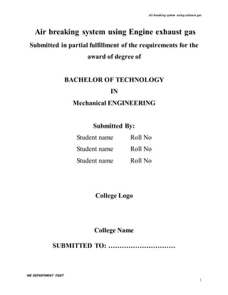
  • 25. Air breaking system using exhaust gas ME DEPARTMENT FGIET 25 the following decade of high performance muscle cars fueling different chambers of the engine's intake manifold. Fig 1 Assembly of Airbrake system using engine Exhaust gas WORKING A two stroke engine powered by petrol is used to produce exhaust gas. Here we are placing a turbine in the path of exhaust from the silencer. The turbine is connected to a dynamo, which is used to generate power. Depending upon the airflow the turbine will start rotating thus rotating the dynamo. A dynamo is a device which is used to convert the kinetic energy into electrical energy. The generated electric power is stored in a battery after rectification. Thus the stored electrical power is use to run the DC compressor the compressor compresses the atmospheric air and it is stored in an air tank. When the brake is applied the 5/2 solenoid valve is activated and it allows the air to actuates the pneumatic cylinder thus the brake is applied. Hardware used:
  • 26. Air breaking system using exhaust gas ME DEPARTMENT FGIET 26  Pneumatic cylinder  Pneumatic solenoid valve  Bearing  Adaptor  Freewheels  Battery 12V  Turbine  Dynamo PNEUMATIC CYLINDER Pneumatic cylinder(s) (sometimes known as air cylinders) are mechanical devices which use the power of compressed gas to produce a force in a reciprocating linear motion. Like hydraulic cylinders, something forces a piston to move in the desired direction. The piston is a disc or cylinder, and the piston rod transfers the force it develops to the object to be moved.[1] :85 Engineers sometimes prefer to use pneumatics because they are quieter, cleaner, and do not require large amounts of space for fluid storage. Because the operating fluid is a gas, leakage from a pneumatic cylinder will not drip out and contaminate the surroundings, making pneumatics more desirable where cleanliness is a requirement. For example, in the mechanical puppets of the Disney Tiki Room, pneumatics are used to prevent fluid from dripping onto people below the puppets TYPES
  • 27. Air breaking system using exhaust gas ME DEPARTMENT FGIET 27 Single-acting cylinders Single-acting cylinders (SAC) use the pressure imparted by compressed air to create a driving force in one direction (usually out), and a spring to return to the "home" tion. More often than not, this type of cylinder has limited extension due to the space the compressed spring takes up. Another downside to SACs is that part of the force produced by the cylinder is lost as it tries to push against the spring Double-acting cylinders Double-acting cylinders (DAC) use the force of air to move in both extend and retract strokes. They have two ports to allow air in, one for outstroke and one for instroke. Stroke length for this design is not limited, however, the piston rod is more vulnerable to buckling and bending. Additional calculations should be performed as well. Multi-stage, telescoping cylinder Telescoping cylinders, also known as telescopic cylinders can be either single or double-acting. The telescoping cylinder incorporates a piston rod nested within a series of hollow stages of increasing diameter. Upon actuation, the piston rod and each succeeding stage "telescopes" out as a segmented piston. The main benefit of this design is the allowance for a notably longer stroke than would be achieved with a single-stage cylinder of the same collapsed (retracted) length. One cited drawback to telescoping cylinders is the increased potential for piston flexion due to the segmented piston design. Consequently, telescoping cylinders are primarily utilized in applications where the piston bears minimal side loading. Other types Although SACs and DACs are the most common types of pneumatic cylinder, the following types are not particularly rare  Through rod air cylinders: piston rod extends through both sides of the cylinder, allowing for equal forces and speeds on either side.  Cushion end air cylinders: cylinders with regulated air exhaust to avoid impacts between the piston rod and the cylinder end cover.
  • 28. Air breaking system using exhaust gas ME DEPARTMENT FGIET 28  Rotary air cylinders: actuators that use air to impart a rotary motion.  Rodless air cylinders: These have no piston rod. They are actuators that use a mechanical or magnetic coupling to impart force, typically to a table or other body that moves along the length of the cylinder body, but does not extend beyond it.  Tandem air cylinder: two cylinders assembled in series  Impact air cylinder: high velocity cylinders with specially designed end covers that withstand the impact of extending or retracting piston rods. COMPONENTS USED  2 STROKE ENGINE  SWITCHES FOR IGNITION ON/OFF AND SELF START  PNEUMATIC CYLINDER  12 DC COMPRESSOR  SOLENOID VALVE  AIR PIPES  12 V BATTERY  DC GENERATOR OR DYNAMO
  • 29. Air breaking system using exhaust gas ME DEPARTMENT FGIET 29 2D VIEW OF AIR BRAKE SYSTEM USING EXHAUST GAS WRKING PRINCIPLE Air from exhaust gas is forced to a turbine which acts as a dynamo, the turbine fan is light material which will rotate for even minimum force of air . The turbine thus produces a milli volts of charge which is shown using a led bulb. A diode is connected to the circuit of the dynamo which is connected to a battery since to have a one way flow of current . thus charge stored in a battery is used to run a 12v dc compressor which actuates flow of air through solenoid valve . the solenoid valve acts as switch for braking mechanism i,e air brake .thus braking facility is obtained by using pneumatic cylinder to a drum brake. Air brakes are very efficient since you only actuate the solenoid valve for braking you do not force your foot for braking continuously. SPECIFICATIONS  PNEUMATIC CYLINDER – 10 Kpa  DC COMPRESSOR – 12 V ENGINE PNEUMATIC CYLINDER WHEEL BRAKE SYSTEM SOLENOID VALVEDC COMPRESSOR BATTERY FRAME EXHAUST TURBINE FAN DYNAMO
  • 30. Air breaking system using exhaust gas ME DEPARTMENT FGIET 30  DYNAMO – 12V  ENGINE – 80 CC SCOOTY  BATTERY – 12V ADVANTAGES Air brakes are used as an alternative to hydraulic brakes which are used on lighter vehicles such as automobiles. Hydraulic brakes use a liquid (hydraulic fluid) to transfer pressure from the brake pedal to the brake shoe to stop the vehicle. Air brakes have several advantages for large multitrailer vehicles  The supply of air is unlimited, so the brake system can never run out of its operating fluid, as hydraulic brakes can. Minor leaks do not result in brake failures.  Air line couplings are easier to attach and detach than hydraulic lines eliminating the risk of air getting into hydraulic fluid since there is no hydraulic fluid. Air brake circuits on trailers can be easily attached and removed by operators with appropriate training.  Air not only serves as a fluid for transmission of force, but also stores potential energy. So it can serve to control the force applied. Air brake systems include an air tank that stores sufficient energy to stop the vehicle if the compressor fails.  Air brakes are effective even with considerable leakage, so an air brake system can be designed with sufficient "fail-safe" capacity to stop the vehicle safely even when leaking 1. It reduces the battery power 2. It increases the engine efficiency 3. It occupies less floor space 4. It reduces the air pollution
  • 31. Air breaking system using exhaust gas ME DEPARTMENT FGIET 31 MILD STEEL ANGLES We have used 1inch width and 3mm thickness mild steel angles in this project. Mild or low-carbon steel Mild steel (iron containing a small percentage of carbon, strong and tough but not readily tempered), also known as plain-carbon steel and low-carbon steel, is now the most common form of steel because its price is relatively low while it provides material properties that are acceptable for many applications. Mild steel contains approximately 0.05–0.25% carbon[1]making it malleable and ductile. Mild steel has a relatively low tensile strength, but it is cheap and easy to form; surface hardness can be increased through carburizing. In applications where large cross-sections are used to minimize deflection, failure by yield is not a risk so low-carbon steels are the best choice, for example as structural steel. The density of mild steel is approximately 7.85 g/cm3 (7850 kg/m3 or 0.284 lb/in3)[4] and the Young's modulus is 200 GPa (29,000 ksi).[5] Low-carbon steels suffer from yield-point runout where the material has two yield points. The first yield point (or upper yield point) is higher than the second and the yield drops dramatically after the upper yield point. If a low-carbon steel is only stressed to some point between the upper and lower yield point then the surface develop Lüder bands Low-carbon steels contain less carbon than other steels and are easier to cold-form, making them easier to handle High-tensile steel High-tensile steels are low-carbon, or steels at the lower end of the medium-carbon range, which have additional alloying ingredients in order to increase their strength, wear properties or specifically tensile strength. These alloying ingredients include chromium, molybdenum, silicon, manganese, nickel and vanadium. Impurities such as phosphorus or sulphur have their maximum allowable content restricted.  41xx steel  4140 steel  4145 steel
  • 32. Air breaking system using exhaust gas ME DEPARTMENT FGIET 32  4340 steel  300M steel  EN25 steel 2½% nickel-chromium-molybdenum steel  EN26 steel Higher-carbon steels Carbon steels which can successfully undergo heat-treatment have a carbon content in the range of 0.30–1.70% by weight. Trace impurities of various other elements can have a significant effect on the quality of the resulting steel. Trace amounts of sulfur in particular make the steel red-short, that is, brittle and crumbly at working temperatures. Low-alloy carbon steel, such as A36 grade, contains about 0.05% sulfur and melts around 1,426–1,538 °C (2,599–2,800 °F).[8] Manganese is often added to improve the hardenability of low-carbon steels. These additions turn the material into a low-alloy steel by some definitions, but AISI's definition of carbon steel allows up to 1.65% manganese by weight. Classification See also: SAE steel grades Carbon steel is broken down into four classes based on carbon content:[1] Low-carbon steel 0.05 to 0.30% carbon content.. Medium-carbon steel Approximately 0.3–0.8% carbon content.[1] Balances ductility and strength and has good wear resistance; used for large parts, forging and automotive components.[9][10]
  • 33. Air breaking system using exhaust gas ME DEPARTMENT FGIET 33 High-carbon steel Approximately 0.8–2.0% carbon content.[1] Very strong, used for springs, edged tools, and high-strength wires. Ultra-high-carbon steel Approximately 3.25–4.0% carbon content.[1] Steels that can be tempered to great hardness. Used for special purposes like (non-industrial-purpose) knives, axles or punches. Most steels with more than 2.5% carbon content are made using powder metallurgy. Heat treatment Iron-carbon phase diagram, showing the temperature and carbon ranges for certain types of heat treatments. Main article: Heat treatment The purpose of heat treating carbon steel is to change the mechanical properties of steel, usually ductility, hardness, yield strength, or impact resistance. Note that the electrical and thermal conductivity are only slightly altered. As with most strengthening techniques for steel, Young's modulus (elasticity) is unaffected. All treatments of steel trade ductility for increased strength and vice versa. Iron has a higher solubility for carbon in the austenite phase; therefore all heat treatments, except spheroidizing and process annealing, start by heating the steel to a temperature at which the austenitic phase can exist. The steel is then quenched (heat drawn out) at a moderate to low rate allowing carbon to diffuse out of the austenite forming iron-carbide (cementite) to precipitate
  • 34. Air breaking system using exhaust gas ME DEPARTMENT FGIET 34 leaving ferrite, or at a high rate, trapping the carbon within the iron thus forming martensite. The rate at which the steel is cooled through the eutectoid temperature (about 727°C) affects the rate at which carbon diffuses out of austenite and forms cementite. Generally speaking, cooling swiftly will leave iron carbide finely dispersed and produce a fine grained pearlite and cooling slowly will give a coarser pearlite. Cooling a hypoeutectoid steel (less than 0.77 wt% C) results in a lamellar-pearlitic structure of iron carbide layers with α-ferrite (nearly pure iron) between. If it is hypereutectoid steel (more than 0.77 wt% C) then the structure is full pearlite with small grains (larger than the pearlite lamella) of cementite formed on the grain boundaries. A eutectoid steel (0.77% carbon) will have a pearlite structure throughout the grains with no cementite at the boundaries. The relative amounts of constituents are found using the lever rule. The following is a list of the types of heat treatments possible:  Spheroidizing: Spheroidite forms when carbon steel is heated to approximately 700 °C for over 30 hours. Spheroidite can form at lower temperatures but the time needed drastically increases, as this is a diffusion-controlled process. The result is a structure of rods or spheres of cementite within primary structure (ferrite or pearlite, depending on which side of the eutectoid you are on). The purpose is to soften higher carbon steels and allow more formability. This is the softest and most ductile form of steel. The image to the right shows where spheroidizing usually occurs.  Full annealing: Carbon steel is heated to approximately 40 °C above Ac3? or Acm? for 1 hour; this ensures all the ferrite transforms into austenite (although cementite might still exist if the carbon content is greater than the eutectoid). The steel must then be cooled slowly, in the realm of 20 °C (36 °F) per hour. Usually it is just furnace cooled, where the furnace is turned off with the steel still inside. This results in a coarse pearlitic structure, which means the "bands" of pearlite are thick. Fully annealed steel is soft and ductile, with no internal stresses, which is often necessary for cost-effective forming. Only spheroidized steel is softer and more ductile.  Process annealing: A process used to relieve stress in a cold-worked carbon steel with less than 0.3% C. The steel is usually heated to 550–650 °C for 1 hour, but
  • 35. Air breaking system using exhaust gas ME DEPARTMENT FGIET 35 sometimes temperatures as high as 700 °C. The image rightward shows the area where process annealing occurs.  Isothermal annealing: It is a process in which hypoeutectoid steel is heated above the upper critical temperature. This temperature is maintained for a time and then reduced to below the lower critical temperature and is again maintained. It is then cooled to room temperature. This method eliminates any temperature gradient.  Normalizing: Carbon steel is heated to approximately 55 °C above Ac3 or Acm for 1 hour; this ensures the steel completely transforms to austenite. The steel is then air- cooled, which is a cooling rate of approximately 38 °C (100 °F) per minute. This results in a fine pearlitic structure, and a more-uniform structure. Normalized steel has a higher strength than annealed steel; it has a relatively high strength and hardness.[15]  Quenching: Carbon steel with at least 0.4 wt% C is heated to normalizing temperatures and then rapidly cooled (quenched) in water, brine, or oil to the critical temperature. The critical temperature is dependent on the carbon content, but as a general rule is lower as the carbon content increases. This results in a martensitic structure; a form of steel that possesses a super-saturated carbon content in a deformed body-centered cubic (BCC) crystalline structure, properly termed body- centered tetragonal (BCT), with much internal stress. Thus quenched steel is extremely hard but brittle, usually too brittle for practical purposes. These internal stresses may cause stress cracks on the surface. Quenched steel is approximately three to four (with more carbon) fold harder than normalized steel.  Martempering (Marquenching): Martempering is not actually a tempering procedure, hence the term "marquenching". It is a form of isothermal heat treatment applied after an initial quench, typically in a molten salt bath, at a temperature just above the "martensite start temperature". At this temperature, residual stresses within the material are relieved and some bainite may be formed from the retained austenite which did not have time to transform into anything else. In industry, this is a process used to control the ductility and hardness of a material. With longer marquenching, the ductility increases with a minimal loss in strength; the steel is held in this solution until the inner and outer temperatures of the part equalize. Then the steel is
  • 36. Air breaking system using exhaust gas ME DEPARTMENT FGIET 36 cooled at a moderate speed to keep the temperature gradient minimal. Not only does this process reduce internal stresses and stress cracks, but it also increases the impact resistance.[17]  Tempering: This is the most common heat treatment encountered, because the final properties can be precisely determined by the temperature and time of the tempering. Tempering involves reheating quenched steel to a temperature below the eutectoid temperature then cooling. The elevated temperature allows very small amounts of spheroidite to form, which restores ductility, but reduces hardness. Actual temperatures and times are carefully chosen for each composition.[18]  Austempering: The austempering process is the same as martempering, except the quench is interrupted and the steel is held in the molten salt bath at temperatures between 205°C and 540°C, and then cooled at a moderate rate. The resulting steel, called bainite, produces an acicular microstructure in the steel that has great strength (but less than martensite), greater ductility, higher impact resistance, and less distortion than martensite steel. The disadvantage of austempering is it can be used only on a few steels, and it requires a special salt bath.[19] Case hardening Main article: Case hardening Case hardening processes harden only the exterior of the steel part, creating a hard, wear resistant skin (the "case") but preserving a tough and ductile interior. Carbon steels are not very hardenable meaning they can not be hardened throughout thick sections. Alloy steels have a better hardenability, so they can through-hardened and do not require case hardening. This property of carbon steel can be beneficial, because it gives the surface good wear characteristics but leaves the core tough. WELDING Welding is a fabrication or sculptural process that joins materials, usually metals or thermoplastics, by causing fusion, which is distinct from lower temperature metal-joining techniques such as brazing and soldering, which do not melt the base metal. In addition to melting the base metal, a filler material is typically added to the joint to form a pool
  • 37. Air breaking system using exhaust gas ME DEPARTMENT FGIET 37 of molten material (the weld pool) that cools to form a joint that is usually stronger than the base material. Pressure may also be used in conjunction with heat, or by itself, to produce a weld. Welding also requires a form of shield to protect the filler metals or melted metals from being contaminated or oxidized. Although less common, there are also solid state welding processes such as friction welding in which metal does not melt. Some of the best known welding methods include:  Oxy-fuel welding – also known as oxyacetylene welding or oxy welding, uses fuel gases and oxygen to weld and cut metals.  Shielded metal arc welding (SMAW) – also known as "stick welding" or "electric welding", uses an electrode that has flux around it to protect the weld puddle. The electrode holder holds the electrode as it slowly melts away. Slag protects the weld puddle from atmospheric contamination.  Gas tungsten arc welding (GTAW) – also known as TIG (tungsten, inert gas), uses a non- consumable tungsten electrode to produce the weld. The weld area is protected from atmospheric contamination by an inert shielding gas such as argon or helium.  Gas metal arc welding (GMAW) – commonly termed MIG (metal, inert gas), uses a wire feeding gun that feeds wire at an adjustable speed and flows an argon-based shielding gas or a mix of argon and carbon dioxide (CO2) over the weld puddle to protect it from atmospheric contamination.  Flux-cored arc welding (FCAW) – almost identical to MIG welding except it uses a special tubular wire filled with flux; it can be used with or without shielding gas, depending on the filler.  Submerged arc welding (SAW) – uses an automatically fed consumable electrode and a blanket of granular fusible flux. The molten weld and the arc zone are protected from atmospheric contamination by being "submerged" under the flux blanket.  Electroslag welding (ESW) – a highly productive, single pass welding process for thicker materials between 1 inch (25 mm) and 12 inches (300 mm) in a vertical or close to vertical position.
  • 38. Air breaking system using exhaust gas ME DEPARTMENT FGIET 38  Electric resistance welding (ERW) – a welding process that produces coalescence of laying surfaces where heat to form the weld is generated by the electrical resistance of the material. In general, an efficient method, but limited to relatively thin material. Many different energy sources can be used for welding, including a gas flame, an electric arc, a laser, an electron beam, friction, and ultrasound. While often an industrial process, welding may be performed in many different environments, including in open air, under water, and in outer space. Welding is a hazardous undertaking and precautions are required to avoid burns, electric shock, vision damage, inhalation of poisonous gases and fumes, and exposure to intense ultraviolet radiation. Until the end of the 19th century, the only welding process was forge welding, which blacksmiths had used for millennia to join iron and steel by heating and hammering. Arc weldingand oxyfuel welding were among the first processes to develop late in the century, and electric resistance welding followed soon after. Welding technology advanced quickly during the early 20th century as the world wars drove the demand for reliable and inexpensive joining methods. Following the wars, several modern welding techniques were developed, including manual methods like SMAW, now one of the most popular welding methods, as well as semi- automatic and automatic processes such as GMAW, SAW, FCAW and ESW. Developments continued with the invention of laser beam welding, electron beam welding, magnetic pulse welding (MPW), and friction stir welding in the latter half of the century. Today, the science continues to advance. Robot welding is commonplace in industrial settings, and researchers continue to develop new welding methods and gain greater understanding of weld quality. PROCESSES Arc
  • 39. Air breaking system using exhaust gas ME DEPARTMENT FGIET 39 Man welding a metal structure in a newly constructed house in Bengaluru, India These processes use a welding power supply to create and maintain an electric arc between an electrode and the base material to melt metals at the welding point. They can use either direct current (DC) or alternating current (AC), and consumable or non-consumable electrodes. The welding region is sometimes protected by some type of inert or semi-inert gas, known as a shielding gas, and filler material is sometimes used as well. Power supplies To supply the electrical power necessary for arc welding processes, a variety of different power supplies can be used. The most common welding power supplies are constant current power supplies and constant voltage power supplies. In arc welding, the length of the arc is directly related to the voltage, and the amount of heat input is related to the current. Constant current power supplies are most often used for manual welding processes such as gas tungsten arc welding and shielded metal arc welding, because they maintain a relatively constant current even as the voltage varies. This is important because in manual welding, it can be difficult to hold the electrode perfectly steady, and as a result, the arc length and thus voltage tend to fluctuate. Constant voltage power supplies hold the voltage constant and vary the current, and as a result, are most often used for automated welding processes such as gas metal arc welding, flux cored arc welding, and submerged arc welding. In these processes, arc length is kept constant, since any fluctuation in the distance between the wire and the base material is quickly rectified by a large change in current. For example, if the wire and the base material get too close, the current will rapidly increase, which in turn causes the heat to increase and the tip of the wire to melt, returning it to its original separation distance. The type of current used plays an important role in arc welding. Consumable electrode processes such as shielded metal arc welding and gas metal arc welding generally use direct current, but the electrode can be charged either positively or negatively. In welding, the positively
  • 40. Air breaking system using exhaust gas ME DEPARTMENT FGIET 40 charged anode will have a greater heat concentration, and as a result, changing the polarity of the electrode affects weld properties. If the electrode is positively charged, the base metal will be hotter, increasing weld penetration and welding speed. Alternatively, a negatively charged electrode results in more shallow welds. Nonconsumable electrode processes, such as gas tungsten arc welding, can use either type of direct current, as well as alternating current. However, with direct current, because the electrode only creates the arc and does not provide filler material, a positively charged electrode causes shallow welds, while a negatively charged electrode makes deeper welds.[27] Alternating current rapidly moves between these two, resulting in medium-penetration welds. One disadvantage of AC, the fact that the arc must be re-ignited after every zero crossing, has been addressed with the invention of special power units that produce a square wave pattern instead of the normal sine wave, making rapid zero crossings possible and minimizing the effects of the problem. ] Processes One of the most common types of arc welding is shielded metal arc welding (SMAW); ] it is also known as manual metal arc welding (MMA) or stick welding. Electric current is used to strike an arc between the base material and consumable electrode rod, which is made of filler material (typically steel) and is covered with a flux that protects the weld area from oxidation and contamination by producing carbon dioxide (CO2) gas during the welding process. The electrode core itself acts as filler material, making a separate filler unnecessary. Shielded metal arc welding The process is versatile and can be performed with relatively inexpensive equipment, making it well suited to shop jobs and field work An operator can become reasonably proficient with a modest amount of training and can achieve mastery with experience. Weld times are rather slow, since the consumable electrodes must be frequently replaced and because slag, the residue from the flux, must be chipped away after welding. Furthermore, the process is generally limited to welding ferrous materials, though special electrodes have made possible the welding of cast iron, nickel, aluminum, copper, and other metals.
  • 41. Air breaking system using exhaust gas ME DEPARTMENT FGIET 41 Diagram of arc and weld area, in shielded metal arc welding. 1. Coating Flow 2. Rod 3. Shield Gas 4. Fusion 5. Base metal 6. Weld metal 7. Solidified Slag Gas metal arc welding (GMAW), also known as metal inert gas or MIG welding, is a semi- automatic or automatic process that uses a continuous wire feed as an electrode and an inert or semi-inert gas mixture to protect the weld from contamination. Since the electrode is continuous, welding speeds are greater for GMAW than for SMAW. A related process, flux-cored arc welding (FCAW), uses similar equipment but uses wire consisting of a steel electrode surrounding a powder fill material. This cored wire is more expensive than the standard solid wire and can generate fumes and/or slag, but it permits even higher welding speed and greater metal penetration. Gas tungsten arc welding (GTAW), or tungsten inert gas (TIG) welding, is a manual welding process that uses a nonconsumable tungstenelectrode, an inert or semi-inert gas mixture, and a separate filler material.[33] Especially useful for welding thin materials, this method is
  • 42. Air breaking system using exhaust gas ME DEPARTMENT FGIET 42 characterized by a stable arc and high quality welds, but it requires significant operator skill and can only be accomplished at relatively low speeds. GTAW can be used on nearly all weldable metals, though it is most often applied to stainless steel and light metals. It is often used when quality welds are extremely important, such as in bicycle, aircraft and naval applications. A related process, plasma arc welding, also uses a tungsten electrode but uses plasma gas to make the arc. The arc is more concentrated than the GTAW arc, making transverse control more critical and thus generally restricting the technique to a mechanized process. Because of its stable current, the method can be used on a wider range of material thicknesses than can the GTAW process and it is much faster. It can be applied to all of the same materials as GTAW except magnesium, and automated welding of stainless steel is one important application of the process. A variation of the process is plasma cutting, an efficient steel cutting process. Submerged arc welding (SAW) is a high-productivity welding method in which the arc is struck beneath a covering layer of flux. This increases arc quality, since contaminants in the atmosphere are blocked by the flux. The slag that forms on the weld generally comes off by itself, and combined with the use of a continuous wire feed, the weld deposition rate is high. Working conditions are much improved over other arc welding processes, since the flux hides the arc and almost no smoke is produced. The process is commonly used in industry, especially for large products and in the manufacture of welded pressure vessels. Other arc welding processes include atomic hydrogen welding, electroslag welding, electrogas welding, and stud arc welding. Gas welding Main article: Oxy-fuel welding and cutting The most common gas welding process is oxyfuel welding,[13] also known as oxyacetylene welding. It is one of the oldest and most versatile welding processes, but in recent years it has become less popular in industrial applications. It is still widely used for welding pipes and tubes, as well as repair work. The equipment is relatively inexpensive and simple, generally employing the combustion of acetylene in oxygen to produce a welding flame temperature of about 3100 °C. The flame, since
  • 43. Air breaking system using exhaust gas ME DEPARTMENT FGIET 43 it is less concentrated than an electric arc, causes slower weld cooling, which can lead to greater residual stresses and weld distortion, though it eases the welding of high alloy steels. A similar process, generally called oxyfuel cutting, is used to cut metals. Resistance Main article: Resistance welding Resistance welding involves the generation of heat by passing current through the resistance caused by the contact between two or more metal surfaces. Small pools of molten metal are formed at the weld area as high current (1000–100,000 A) is passed through the metal.[37] In general, resistance welding methods are efficient and cause little pollution, but their applications are somewhat limited and the equipment cost can be high.[37] Spot welder Spot welding is a popular resistance welding method used to join overlapping metal sheets of up to 3 mm thick Two electrodes are simultaneously used to clamp the metal sheets together and to pass current through the sheets. The advantages of the method include efficient energy use, limited workpiece deformation, high production rates, easy automation, and no required filler materials. Weld strength is significantly lower than with other welding methods, making the process suitable for only certain applications. It is used extensively in the automotive industry— ordinary cars can have several thousand spot welds made by industrial robots. A specialized process, called shot welding, can be used to spot weld stainless steel. Like spot welding, seam welding relies on two electrodes to apply pressure and current to join metal sheets. However, instead of pointed electrodes, wheel-shaped electrodes roll along and often feed the workpiece, making it possible to make long continuous welds. In the past, this
  • 44. Air breaking system using exhaust gas ME DEPARTMENT FGIET 44 process was used in the manufacture of beverage cans, but now its uses are more limited. Other resistance welding methods include butt welding, flash welding, projection welding, and upset welding. Energy beam Energy beam welding methods, namely laser beam welding and electron beam welding, are relatively new processes that have become quite popular in high production applications. The two processes are quite similar, differing most notably in their source of power. Laser beam welding employs a highly focused laser beam, while electron beam welding is done in a vacuum and uses an electron beam. Both have a very high energy density, making deep weld penetration possible and minimizing the size of the weld area. Both processes are extremely fast, and are easily automated, making them highly productive. The primary disadvantages are their very high equipment costs (though these are decreasing) and a susceptibility to thermal cracking. Developments in this area include laser-hybrid welding, which uses principles from both laser beam welding and arc welding for even better weld properties, laser cladding, and x-ray welding Solid-state Like the first welding process, forge welding, some modern welding methods do not involve the melting of the materials being joined. One of the most popular, ultrasonic welding, is used to connect thin sheets or wires made of metal or thermoplastic by vibrating them at high frequency and under high pressure.[41] The equipment and methods involved are similar to that of resistance welding, but instead of electric current, vibration provides energy input. Welding metals with this process does not involve melting the materials; instead, the weld is formed by introducing mechanical vibrations horizontally under pressure. When welding plastics, the materials should have similar melting temperatures, and the vibrations are introduced vertically. Ultrasonic welding is commonly used for making electrical connections out of aluminum or copper, and it is also a very common polymer welding process. Another common process, explosion welding, involves the joining of materials by pushing them together under extremely high pressure. The energy from the impact plasticizes the materials, forming a weld, even though only a limited amount of heat is generated. The process is commonly used for welding dissimilar materials, such as the welding of aluminum with steel in ship hulls or compound plates. Other solid-state welding processes include friction
  • 45. Air breaking system using exhaust gas ME DEPARTMENT FGIET 45 welding (including friction stir welding), magnetic pulse welding co-extrusion welding, cold welding, diffusion bonding, exothermic welding, high frequency welding, hot pressure welding, induction welding, and roll welding PNEUMATIC PIPES Pneumatic tubes (or capsule pipelines; also known as pneumatic tube transport or PTT) are systems that propel cylindrical containers through networks of tubes by compressed air or by partial vacuum. They are used for transporting solid objects, as opposed to conventional pipelines, which transport fluids. Pneumatic tube networks gained acceptance in the late 19th and early 20th centuries for offices that needed to transport small, urgent packages (such as mail, paperwork, or money) over relatively short distances (within a building, or at most, within a city). Some installations grew to great complexity, but were mostly superseded. In some settings, such as hospitals, they remain widespread and have been further extended and developed in the 21st century We have used 8mm pneumatic pipes currently for the passage of air into the cylinder in order to actuate the movement.
  • 46. Air breaking system using exhaust gas ME DEPARTMENT FGIET 46 PNEUMATIC CONNECTORS A hose coupling is a connector on the end of a hose to connect (or couple) it with another hose or with a tap or a hose appliance, such as an irrigation sprinkler. It is usually made of steel, brass, stainless steel, aluminium or plastic. AIR COMPRESSOR An air compressor is a device that converts power (using an electric motor, diesel or gasoline engine, etc.) into potential energy stored in pressurized air (i.e., compressed air). By one of several methods, an air compressor forces more and more air into a storage tank, increasing the pressure. When tank pressure reaches its engineered upper limit the air compressor shuts off. The compressed air, then, is held in the tank until called into use.[1] The energy contained in the compressed air can be used for a variety of applications, utilizing the kinetic energy of the air as it is released and the tank depressurizes. When tank pressure reaches its lower limit, the air compressor turns on again and re-pressurizes the tank.
  • 47. Air breaking system using exhaust gas ME DEPARTMENT FGIET 47 CLASSIFICATION OF COMPRESSORS Compressors can be classified according to the pressure delivered: 1. Low-pressure air compressors (LPACs), which have a discharge pressure of 150 psi or less 2. Medium-pressure compressors which have a discharge pressure of 151 psi to 1,000 psi 3. High-pressure air compressors (HPACs), which have a discharge pressure above 1,000 psi They can also be classified according to the design and principle of operation: 1. Single-Stage Reciprocating Compressor 2. Two-Stage Reciprocating Compressor 3. Compound Compressor 4. Rotary-screw compressor 5. Rotary Vane Compressor 6. Scroll Compressor 7. Turbo compressor 8. Axial Compressor MATERIAL Upon job specification, the material may be chosen. Material range from nickel-plated brass to aluminum, and even steel and stainless steel. Depending on the level of loads, humidity, temperature, and stroke lengths specified, the appropriate material may be selected. Instroke and outstroke Although the diameter of the piston and the force exerted by a cylinder are related, they are not directly proportional to one another. Additionally, the typical mathematical relationship between the two assumes that the air supply does not become saturated. Due to the effective cross sectional area reduced by the area of the piston rod, the instroke force is less than
  • 48. Air breaking system using exhaust gas ME DEPARTMENT FGIET 48 the outstroke force when both are powered pneumatically and by same supply of compressed gas. The relationship between the force, radius, and pressure can derived from simple distributed load equation: AIR RESERVOIR Air reservoir is used for storage of air under pressure. It is made of mild steel. The pressure inside the cylinder is 3 to 5 N/mm 2 . It supplies air to the pneumatic actuators through control valve. WORKING- When link turns through some angle, angle sensor detected the motion. Sensor sends this data to controller and solenoid valve activate. Compressed air in reservoir passes through valve and enters in pneumatic actuator. According to its position cylinder move the links. One link turns its full range angle the another solenoid valve open and pneumatic actuator moves in reverse direction. The compressor that we are using in the project has a capacity to withstand 300psi of pressure.
  • 49. Air breaking system using exhaust gas ME DEPARTMENT FGIET 49 An air compressor is a device that converts power (using an electric motor, diesel or gasoline engine, etc.) into potential energy stored in pressurized air (i.e., compressed air). By one of several methods, an air compressor forces more and more air into a storage tank, increasing the pressure. When tank pressure reaches its engineered upper limit the air compressor shuts off. The compressed air, then, is held in the tank until called into use.[1] The energy contained in the compressed air can be used for a variety of applications, utilizing the kinetic energy of the air as it is released and the tank depressurizes. When tank pressure reaches its lower limit, the air compressor turns on again and re-pressurizes the tank. An air compressor must be differentiated from an air pump which merely pumps air from one context (often the surrounding environment) into another (such as an inflatable mattress, an aquarium, etc.). Air pumps do not contain an air tank for storing pressurized air and are generally much slower, quieter, and less expensive to own and operate than an air compressor. CLASSIFICATIONS Compressors can be classified according to the pressure delivered: 1. Low-pressure air compressors (LPACs), which have a discharge pressure of 150 psi or less 2. Medium-pressure compressors which have a discharge pressure of 151 psi to 1,000 psi 3. High-pressure air compressors (HPACs), which have a discharge pressure above 1,000 psi They can also be classified according to the design and principle of operation: 1. Single-Stage Reciprocating Compressor 2. Two-Stage Reciprocating Compressor 3. Compound Compressor 4. Rotary-screw compressor 5. Rotary Vane Compressor 6. Scroll Compressor 7. Turbo compressor
  • 50. Air breaking system using exhaust gas ME DEPARTMENT FGIET 50 8. Axial Compressor DISPLACEMENT TYPES There are numerous methods of air compression, divided into either positive-displacement or roto-dynamic types. Positive displacement Positive-displacement compressors work by forcing air into a chamber whose volume is decreased to compress the air. Once the maximum pressure is reached, a port or valve opens and air is discharged into the outlet system from the compression chamber.[4] Common types of positive displacement compressors are  Piston-type: air compressors use this principle by pumping air into an air chamber through the use of the constant motion of pistons. They use one-way valves to guide air into and out of a chamber whose base consists of a moving piston. When the piston is on its down stroke, it draws air into the chamber. When it is on Technical Illustration of a two-stage air compressor its up stroke, the charge of air is forced out and into a storage tank. Piston compressors generally fall into two basic categories, single-stage and two-stage. Single stage compressors usually fall into the fractional through 5 horsepower range. Two-stage compressors normally fall Technical Illustration of a portable single-stage air compressor
  • 51. Air breaking system using exhaust gas ME DEPARTMENT FGIET 51 into the 5 through 30 horsepower range. Two-stage compressors provide greater efficiency than their single-stage counterparts. For this reason, these compressors are the most common units within the small business community. The capacities for both single-stage and two- stage compressors is generally provided in horsepower (HP), Standard Cubic feet per Minute (SCFM)* and Pounds per Square Inch (PSI). *To a lesser extent, some compressors are rated in Actual Cubic Feet per Minute (ACFM). Still others are rated in Cubic Feet per Minute(CFM). Using CFM to rate a compressor is incorrect because it represents a flow rate that is independent of a pressure reference. i.e. 20 CFM at 60 PSI.  Rotary screw compressors: use positive-displacement compression by matching two helical screws that, when turned, guide air into a chamber, whose volume is decreased as the screws turn.  Vane compressors: use a slotted rotor with varied blade placement to guide air into a chamber and compress the volume. This type of compressor delivers a fixed volume of air at high pressures. Dynamic displacement Dynamic displacement air compressors include centrifugal compressors and axial compressors. In these types, a rotating component imparts its kinetic energy to the air which is eventually converted into pressure energy. These use centrifugal force generated by a spinning impeller to accelerate and then decelerate captured air, which pressurizes it. APPLICATIONS Air compressors have many uses, including: supplying high-pressure clean air to fill gas cylinders, supplying moderate-pressure clean air to a submerged surface supplied diver, supplying moderate-pressure clean air for driving some office and school building pneumatic HVAC control system valves, supplying a large amount of moderate- pressure air to power pneumatic tools, such as jackhammers, filling high pressure air tanks (HPA), for filling tires, and to produce large volumes of moderate-pressure air for large-scale industrial processes (such as oxidation for petroleum coking or cement plant bag house purge systems).
  • 52. Air breaking system using exhaust gas ME DEPARTMENT FGIET 52 Most air compressors either are reciprocating piston type, rotary vane or rotary screw. Centrifugal compressors are common in very large applications. There are two main types of air-compressor pumps: oil-lubed and oil-less. The oil-less system has more technical development, but is more expensive, louder and lasts for less time than oil-lubed pumps. The oil- less system also delivers air of better quality. The most common types of air compressors are: electric or gas/diesel powered compressors. The power of a compressor is measured in HP (horsepower) and CFM (cubic feet per minute of intake air). The gallon size of the tank specifies the volume of compressed air (in reserve) available. Gas/diesel powered compressors are widely used in remote areas with problematic access to electricity. They are noisy and require ventilation for exhaust gases. Electric powered compressors are widely used in production, workshops and garages with permanent access to electricity. Common workshop/garage compressors are 110-120 Volt or 230-240 Volt. Compressor tank shapes are: "pancake", "twin tank", "horizontal", and "vertical". Depending on a size and purpose compressors can be stationary or portable. BATTERY A rechargeable battery, storage battery, secondary cell, or accumulator is a type of electrical battery which can be charged, discharged into a load, and recharged many times, as opposed to a disposable or primary battery, which is supplied fully charged and discarded after use. It is composed of one or more electrochemical cells. The term "accumulator" is used as it accumulates and stores energy through a reversible electrochemical reaction. Rechargeable batteries are produced in many different shapes and sizes, ranging from button cells to megawatt systems connected to stabilize an electrical distribution network. Several different combinations of electrode materials and electrolytes are used, including lead–acid, nickel– cadmium (NiCd), nickel–metal hydride (NiMH), lithium-ion (Li-ion), and lithium-ion polymer(Li-ion polymer). Rechargeable batteries typically initially cost more than disposable batteries, but have a much lower total cost of ownership and environmental impact, as they can be recharged inexpensively
  • 53. Air breaking system using exhaust gas ME DEPARTMENT FGIET 53 many times before they need replacing. Some rechargeable battery types are available in the same sizes and voltages as disposable types, and can be used interchangeably with them. APPLICATIONS Devices which use rechargeable batteries include automobile starters, portable consumer devices, light vehicles (such as motorized wheelchairs, golf carts, electric bicycles, and electric forklifts), tools, uninterruptible power supplies, and battery storage power stations. Emerging applications in hybrid internal combustion-battery and electric vehicles drive the technology to reduce cost, weight, and size, and increase lifetime. Older rechargeable batteries self-discharge relatively rapidly, and require charging before first use; some newer low self-discharge NiMH batteries hold their charge for many months, and are typically sold factory-charged to about 70% of their rated capacity. Battery storage power stations use rechargeable batteries for load-leveling (storing electric energy at times of low demand for use during peak periods) and for renewable energy uses (such as storing power generated from photovoltaic arrays during the day to be used at night). Load- leveling reduces the maximum power which a plant must be able to generate, reducing capital cost and the need for peaking power plants. The US National Electrical Manufacturers Association estimated in 2006 that US demand for rechargeable batteries was growing twice as fast as demand for disposables.
  • 54. Air breaking system using exhaust gas ME DEPARTMENT FGIET 54 Small rechargeable batteries can power portable electronic devices, power tools, appliances, and so on. Heavy-duty batteries power electric vehicles, ranging from scooters to locomotives and ships. They are used in distributed electricity generation and in stand-alone power systems. CHARGING AND DISCHARGING During charging, the positive active material is oxidized, producing electrons, and the negative material is reduced, consuming electrons. These electrons constitute the current flow in the external circuit. The electrolyte may serve as a simple buffer for internal ion flow between the electrodes, as in lithium-ion and nickel-cadmium cells, or it may be an active participant in the electrochemical reaction, as in lead–acidcells. The energy used to charge rechargeable batteries usually comes from a battery charger using AC mains electricity, although some are equipped to use a vehicle's 12-volt DC power outlet. The voltage of the source must be higher than that of the battery to force current to flow into it, but not too much higher or the battery may be damaged. Chargers take from a few minutes to several hours to charge a battery. Slow "dumb" chargers without voltage or temperature-sensing capabilities will charge at a low rate, typically taking 14 hours or more to reach a full charge. Rapid chargers can typically charge cells in two to five hours, depending on the model, with the fastest taking as little as fifteen minutes. Fast chargers must have multiple ways of detecting when a cell reaches full charge (change in terminal voltage, temperature, etc.) to stop charging before harmful overcharging or overheating occurs. The fastest chargers often incorporate cooling fans to keep the cells from overheating. Battery packs intended for rapid charging may include a temperature sensor that the charger uses to protect the pack; the sensor will have one or more additional electrical contacts. Different battery chemistries require different charging schemes. For example, some battery types can be safely recharged from a constant voltage source. Other types need to be charged with a regulated current source that tapers as the battery reaches fully charged voltage. Charging a battery incorrectly can damage a battery; in extreme cases, batteries can overheat, catch fire, or explosively vent their contents
  • 55. Air breaking system using exhaust gas ME DEPARTMENT FGIET 55 zYPES The lead–acid battery, invented in 1859 by French physicist Gaston Planté, is the oldest type of rechargeable battery. Despite having a very low energy-to-weight ratio and a low energy-to- volume ratio, its ability to supply high surge currents means that the cells have a relatively large power-to-weight ratio. These features, along with the low cost, makes it attractive for use in motor vehicles to provide the high current required by automobile starter motors. The nickel–cadmium battery (NiCd) was invented by Waldemar Jungner of Sweden in 1899. It uses nickel oxide hydroxide and metallic cadmium as electrodes. Cadmium is a toxic element, and was banned for most uses by the European Union in 2004. Nickel–cadmium batteries have been almost completely superseded by nickel–metal hydride (NiMH) batteries. The nickel–metal hydride battery (NiMH) became available in 1989 These are now a common consumer and industrial type. The battery has a hydrogen-absorbing alloy for the negative electrode instead of cadmium. The lithium-ion battery was introduced in the market in 1991, is the choice in most consumer electronics, having the best energy density and a very slow loss of charge when not in use. It does have drawbacks too, particularly the risk of unexpected ignition from the heat generated by the battery . Such incidents are rare and according to experts, they can be minimized "via appropriate design, installation, procedures and layers of safeguards" so the risk is acceptable. Lithium-ion polymer batteries (LiPo) are light in weight, offer slightly higher energy density than Li-ion at slightly higher cost, and can be made in any shape. They are available but have not displaced Li-ion in the market A primary use is for LiPo batteries is in powering remote- controlled cars, boats and airplanes. LiPo packs are readily available on the consumer market, in various configurations, up to 44.4v, for powering certain R/C vehicles and helicopters or drones. Some test reports warn of the risk of fire when the batteries are not used in accordance with the instructions. Independent reviews of the technology discuss the risk of fire and explosion from Lithium-ion batteries under certain conditions because they use liquid electrolytes.
  • 56. Air breaking system using exhaust gas ME DEPARTMENT FGIET 56 ALTERNATIVES A rechargeable battery is only one of several types of rechargeable energy storage systems. ] Several alternatives to rechargeable batteries exist or are under development. For uses such as portable radios, rechargeable batteries may be replaced by clockwork mechanisms which are wound up by hand, driving dynamos, although this system may be used to charge a battery rather than to operate the radio directly. Flashlights may be driven by a dynamo directly. For transportation, uninterruptible power supply systems and laboratories, flywheel energy storage systems store energy in a spinning rotor for conversion to electric power when needed; such systems may be used to provide large pulses of power that would otherwise be objectionable on a common electrical grid. Ultracapacitors—capacitors of extremely high value— are also used; an electric screwdriver which charges in 90 seconds and will drive about half as many screws as a device using a rechargeable battery was introduced in 2007, and similar flashlights have been produced. In keeping with the concept of ultracapacitors, betavoltaic batteries may be utilized as a method of providing a trickle-charge to a secondary battery, greatly extending the life and energy capacity of the battery system being employed; this type of arrangement is often referred to as a "hybrid betavoltaic power source" by those in the industry. Ultracapacitors are being developed for transportation, using a large capacitor to store energy instead of the rechargeable battery banks used in hybrid vehicles. One drawback of capacitors compared to batteries is that the terminal voltage drops rapidly; a capacitor that has 25% of its initial energy left in it will have one-half of its initial voltage. By contrast, battery systems tend to have a terminal voltage that does not decline rapidly until nearly exhausted. The undesirable characteristic complicates the design of power electronics for use with ultracapacitors. However, there are potential benefits in cycle efficiency, lifetime, and weight compared with rechargeable systems. China started using ultracapacitors on two commercial bus routes in 2006; one of them is route 11 in Shanghai. Flow batteries, used for specialized applications, are recharged by replacing the electrolyte liquid. A flow battery can be considered to be a type of rechargeable fuel cell
  • 57. Air breaking system using exhaust gas ME DEPARTMENT FGIET 57 SOLENOID VALVE A solenoid valve is an electromechanically operated valve. The valve is controlled by an electric current through a solenoid: in the case of a two-port valve the flow is switched on or off; in the case of a three-port valve, the outflow is switched between the two outlet ports. Multiple solenoid valves can be placed together on a manifold. Solenoid valves are the most frequently used control elements in fluidics. Their tasks are to shut off, release, dose, distribute or mix fluids. They are found in many application areas. Solenoids offer fast and safe switching, high reliability, long service life, good medium compatibility of the materials used, low control power and compact design. Besides the plunger-type actuator which is used most frequently, pivoted-armature actuators and rocker actuators are also used. Materials The valve body must be compatible with the fluid; common materials are brass, stainless steel, aluminum, and plastic.[12] The seals must be compatible with the fluid. To simplify the sealing issues, the plugnut, core, springs, shading ring, and other components are often exposed to the fluid, so they must be compatible as well. The requirements present some special problems. The core tube needs to be non-magnetic to pass the solenoid's field through to the plugnut and the core. The plugnut and core need a material with good magnetic properties such as iron, but iron is prone to corrosion. Stainless steels can be used because they come in both magnetic and non-magnetic varieties.[13] For example, a solenoid valve might use 304 stainless steel for the body, 305 stainless steel for the core tube, 302 stainless steel for the springs, and 430 F stainless steel (a magnetic stainless steel[14]) for the core and plugnut TYPES Many variations are possible on the basic, one-way, one-solenoid valve described above:
  • 58. Air breaking system using exhaust gas ME DEPARTMENT FGIET 58  one- or two-solenoid valves;  direct current or alternating current powered;  different number of ways and positions; COMMON USES Solenoid valves are used in fluid power pneumatic and hydraulic systems, to control cylinders, fluid power motors or larger industrial valves. Automatic irrigation sprinkler systems also use solenoid valves with an automatic controller. Domestic washing machines and dishwashers use solenoid valves to control water entry into the machine. They are also often used in paintball gun triggers to actuate the CO2 hammer valve. Solenoid valves are usually referred to simply as "solenoids." Solenoid valves can be used for a wide array of industrial applications, including general on-off control, calibration and test stands, pilot plant control loops, process control systems, and various original equipment manufacturer applications. [
  • 59. Air breaking system using exhaust gas ME DEPARTMENT FGIET 59 MAINTENANCE To ensure all compressor types run efficiently with no leaks, it is imperative to perform routine maintenance, such as monitoring and replacing air compressor fittings.[8] It is suggested that air compressor owners perform daily inspections of their equipment, such as:  Checking for oil and air leaks  Checking the differential pressure in the compressed air filter  Determining whether or not the oil in the compressor should be changed  Verify safe operating temperature to avoid overheating the unit and it is used in sucking the air  Draining condensed moisture from the tank CALCULATIONS OF AIR BRAKE SYSTEM USING EXHAUST GAS ( DC MOTOR ) SAMPLE CALCULATION Motor 1624T009S is to be operated with 9 volts applied to the motor terminals. The torque load is 0.2 oz-in. Find the resulting motor speed, motor current, efficiency, and mechanical power output. From the motor datasheet, it can be seen that the no-load speed of the motor at 12 volts is 11,700 rpm. If the torque load is not coupled to the motor shaft, the motor would run at this speed. The motor speed under load is simply the no-load speed less the reduction in speed due to the load. The proportionality constant for the relationship between motor speed and motor torque is the slope of the torque vs. speed curve, given by the motor no-load speed divided by the stall torque. In this example, the speed reduction caused by the 0.2 oz -in torque load is: 0.2 oz-in x (11,700 rpm/.634 oz-in) = -3,690 rpm The motor speed under load must then be: 11,700 rpm - 3,690 rpm = 8,010 rpm
  • 60. Air breaking system using exhaust gas ME DEPARTMENT FGIET 60 The motor current under load is the sum of the no-load current and the current resulting from the load. The proportionality constant relating current to torque load is the torque constant (kM), in this case, 1.039 oz -in/A. In this case, the load torque is 0.2 oz-in, and the current resulting from the load must be: I = 0.2 oz-in x 1 amp/1.039 oz -in = 192 mA The total motor current must be the sum of this value and the motor no-load current. The data sheet lists the motor no-load current as 60 mA. Therefore, the total current is: 192 mA + 12 mA = 204 mA The mechanical power output of the motor is simply the product of the motor speed and the torque load with a correction factor for units (if required). Therefore, the mechanical power output of the motor in this application is: output power = 0.2 oz-in x 8,010 rpm x 0.00074 = 1.18 Watts The mechanical power input to the motor is the product of the applied voltage and the total motor current in Amps. In this application: input power = 9 volts x 0.203 A = 1.82Watts Since efficiency is simply power out divided by power in, the efficiency in this application is: efficiency = 1.18 Watts / 1.82 Watts = 0.65 = 65% COMPONENTS LISTS AND COST ESTIMATION  ENGINE – SCOOTY ENGINE – 8000  PNEUMATIC VALVE- 600  CHASIS – 1500  PNEUMATIC CYLINDER- 1200  DC GENERATOR – 300  BATTERY 12V- 450
  • 61. Air breaking system using exhaust gas ME DEPARTMENT FGIET 61  DC COMPRESSOR – 4000  WIRING AND SWITCHING – 200  DEVELOPMENT COST – 5000  MISCILLEANOUS - 2000
  • 62. Air breaking system using exhaust gas ME DEPARTMENT FGIET 62 CHAPTER 4 ADVANTAGES AND APPLICATIONS
  • 63. Air breaking system using exhaust gas ME DEPARTMENT FGIET 63 ADVANTAGES It reduces the battery power 2.It increases the engine efficiency 3.It occupies less floor space 4.It reduces the air pollution DISADVANTAGES 1.Initial cost is high 2.Need a separate compressor 3.Maintenance cost is high APPLICATIONS 1.For automobile application 2.Industrial application
  • 64. Air breaking system using exhaust gas ME DEPARTMENT FGIET 64 CHAPTER 5 CONCLUSION
  • 65. Air breaking system using exhaust gas ME DEPARTMENT FGIET 65 CONCLUSIONS In this project we have obtained a revolutionary process in the field of mechanical and automobile. Here the pneumatic cylinder is actuated by using the compressor that is powered by the elect rical power generated from the engine’s exhaust gas. This project has also reduced the cost involved in the concern. It has been designed to perform the entire requirement task which has also been provided.
  • 66. Air breaking system using exhaust gas ME DEPARTMENT FGIET 66 CHAPTER 6 REFERENCES
  • 67. Air breaking system using exhaust gas ME DEPARTMENT FGIET 67 REFERENCES [1] Development of a model for an air brake system with leaks -Srivatsan Ramarathnam (est.al)- 2003 [2] Pressure control scheme for air brakes in commercial vehicles -C.L. Bowlin (est.al)- Apr 2006 [3]A new advanced power-generation system using chemical-looping combustion-Masaru Ishida Diesel engine exhaust gas recirculation-Ming Zheng (est.al)-2011 [4] Power generation with gas turbine systems and combined heat and power-P.A Pilavachi-2004 [5] Power generation using coir pith and wood derived producer gas in diesel engines-A.S. Ramadhas (est.al) [6] A Diagnostic System for Air Brakes in Commercial Vehicles-Swaroop Darbha -2009
  • 68. Air breaking system using exhaust gas ME DEPARTMENT FGIET 68 Shop online @ www.eroletech.com Call Now: +91 7007957715, +91 7081584848 Email: eroletech@gmail.com Alsodeals inElectronic Kits, Components, Modules&Mechanical Parts Lowest Cost Guaranty