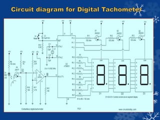
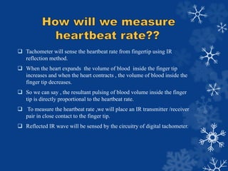
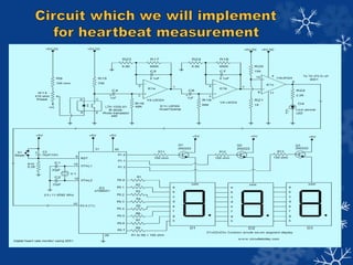
digital tachometer is used to measure heart beat rate by measuring the no of pulses in the finger tip due to pumping of blood by heart.when heart pumps blood,volume of blood inside finger tip increases on the other hand when heart contracts,volume of blood inside finger tip decreases.
2. Introduction
Applications of Tachometer
Working Principle
Circuit diagram of Tachometer
Technique of heartbeat measurement
Relevant circuitry for heartbeat measurement
Circuit description
Application areas of our project
Future scopes
Conclusion
References
3. The word tachometer is derived from two Greek words: tachos means “speed”
and metron means “to measure”.A tachometer is a sensor device for measuring
the rotation speed of an object such as engine shaft in a car . It indicates the
number of revolutions per minute(RPM) performed by an object.
Types of tachometer commonly available:-
Analog Tachometer :- Comprises needle and dial type interface.
Digital Tachometer :- Comprises LCD or LED readout and a memory.
Contact/Non-Contact tachometer :- Sensor is in directly contact with
rotating shaft in case of contact type.
Time/Frequency measuring tachometer :-Time measuring device calculates
speed by measuring time b/w incoming pulses whereas frequency
measuring devices measures the frequency of incoming pulses.
4. Electric tachometers are utilized in machinery and automobiles.
Tachometers are used in aircraft , rails,automobiles and other vehicles
for indicating the rotation rate of the crankshaft of the engine.
Used in traffic engineering to estimate traffic speed and volume.
Used in stationary engines
Used for measuring heart rate , arterial blood flow rate , respiratory gas
flow rate in medical.
5. Analog Tachometer
Has a needle and dial type
interface.
No provision for storage of
reading.
Can not compute average ,
deviation , etc.
Digital Tachometer
Has a LCD & LED layout.
Memory is provided for
storage.
Can perform statistical
functions like averaging etc.
6. The basic principle involves a system with a sensor, a controller and a
display unit . The sensor comprises IR diode and a phototransistor, the
controller used is the microcontroller loaded with a compiled code and the
seven segment display is being interfaced with it , displaying the speed of
the motor. The sensor senses the speed of the motor without actually being
in contact with it by the principle of IR reflection technique and generates
a signal. This signal is converted into an electric signal and fed to the
microcontroller, which is programmed to calculate the speed in terms of
number of motor revolutions in one minute. This speed is displayed on the
interfaced display unit.
7.
8. Tachometer will sense the heartbeat rate from fingertip using IR
reflection method.
When the heart expands the volume of blood inside the finger tip
increases and when the heart contracts , the volume of blood inside the
finger tip decreases.
So we can say , the resultant pulsing of blood volume inside the finger
tip is directly proportional to the heartbeat rate.
To measure the heartbeat rate ,we will place an IR transmitter /receiver
pair in close contact to the finger tip.
Reflected IR wave will be sensed by the circuitry of digital tachometer.
11. 1.SENSOR
Sensor comprises IR diode and phototransistor
in a single package.
When the finger tip is placed over the sensor
,volumetric pulsing of the blood volume inside
the finger tip due to heart beat varies the
intensity of the reflected beam .
According to the intensity of reflected IR
wave , collector current in phototransistor
varies.
Variation in collector voltage is directly
proportional to heart beat rate.
12. 2. Active low pas filter
voltage variation produced by phototransistor is
very feeble so high gain low pass filters will be
used to make the voltage variation sensable by
microcontroller.
It will also eliminate the noise signal.
3.Comparator
The output voltage level of the filter stage will
be fluctuating and this fluctuation will be converted
into a 0 to 5V swing to feed into controller
using the comparator.
We will set the threshold voltage of comparator.
13. 4. 8051 Microcontroller
Microcontroller is used to count the pulses which is directly proportional to
heartbeat rate.
For counting purpose both the timers of 8051 (Timer0 and Timer1) will be used.
Timer 1 will be configured as counter for registering the number of incoming
pulses and Timer0 will be configured as timer which will generate the necessary
time span for the Timer1 to count.
5. Seven segment display
Seven segment display will be interfaced with microcontroller so that it may
display the counting result which will be proportional to heartbeat rate.
6.Low power LED
when we’ll put fingertip on sensor , LED will start blinking indicating that
circuit is working. we’ll turn off the power and according to our program we
will have to wait for sometime to get heart rate in display unit.
14. Can be widely used as a training aid for a variety of sports.
Can be used in Hospitals / Dispensaries
Better and accurate method of measuring heart beat at homes.
Quite useful for people staying at villages.
15. Bio medical signals like breathing rate measurement & pulse oximetry.
It can be configured for choice operations such as security lock against
unauthorized access.
Integrated alarm system may be configured for showing unhealthy heart
condition.
We can use the inbuilt memory for data storage for a comparative
examination.
16. We have not implemented the circuit yet but made a thorough study
regarding the generation and measurement of the signal. We made an
in-depth review of the major functional blocks required for
implementation , examined various circuit components as per the need
and requirements and will implement the circuit in the next semester .
Main aim is to design a tachometer which could be affordable by all for
measuring pulse rate and thereby prevent cardiac issues . If time
permits, we will try to extend the functionality of our tachometer .