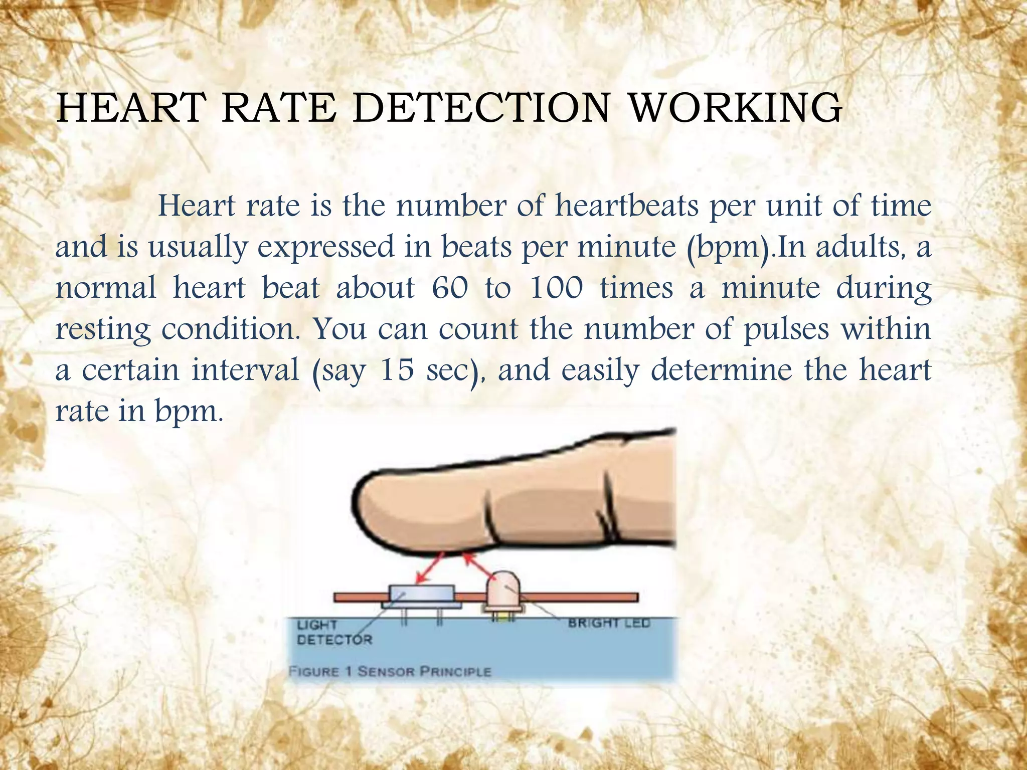
Presenting by
Girish KumarS M
Ganesh KumarJR
Bhanuprakash C
NarayanaSwamy K
Shaik Saif Ulla
Subramani YN
Subramani S
Madhu M S
Guiding by:-
Mr. M.
ANANTHRAMME
Selection Grade Lecturer
Department of Electronics
and communication
engineering
INTRODUCTION
Heart rate measurement indicates the soundness of the
human cardiovascular system. This project demonstrates a
technique to measure the heart rate by sensing the change in
blood volume in a finger artery while the heart is pumping the
blood. Heart rate can be measured either by the ECG waveform
or by the blood flow into the finger (pulse method). The blood
flow into the finger can be sensed photo electrically. To count
the heart beats, here we use a small light source on one side of
the finger (thumb) and observe the change in light intensity on
the other side.
1. Digital / Optical Hear Rate Sensor Interfacing (No need any
circuit calibration)
2. Heart rate Sampling Time = > 20 (15) seconds
3. 3 digit seven segment LED Display
4. On board LED indicator for Heart Pulse
5. On board Start-Stop and Reset Switches
6. Microcontroller based design for greater flexibility
7. Operating voltage – 9 to 12V DC
8. Operating current – 500 ma (Approx.)
9. Diode protection for reverse polarity connection of DC supply
to the PCB
10.Onboard regulator for regulated supply to the kit
Specifications And Features:
.
The block diagram consists of following
functional blocks
1. Microcontroller
2. Heart rate sensor
3. Display
4. Oscillator
1.Microcontroller (PIC16F72)
Microcontroller is the heart of the circuit which
controls all the operations of the circuit using a
Microcontroller greatly reduces the components count
while providing more features than could be found using
dedicated logic ICs. Once the start button pressed the
Microcontroller enable the heart rate sensor module for 15
sec during this interval the No. Of pulses arriving in body
counted through the sensors.
1. High performance RISC CPU
2. Operating speed: DC - 20 MHz clock input DC - 200 ns
instruction cycle
3. 2 ~ 4K FLASH Program Memory,
4. 128 bytes of Data Memory (RAM)
5. 10-bit multi-channel Analog-to-Digital converter
6. Programmable code protection
7. Power saving SLEEP mode
8. Selectable oscillator options
9. Low power, high speed CMOS FLASH / EEPROM technology
SPECIAL MICROCONTROLLER FEATURES:
Heart beat sensor is designed to give digital output of
heat beat when a finger is placed on it. When the heart beat
detector is working, the beat LED flashes in unison with each
heartbeat. This digital output can be connected to
microcontroller directly to measure the Beats per Minute (BPM)
rate. It works on the principle of light modulation by blood flow
through finger at each pulse.
2. Heart rate sensor
A seven-segment display, less commonly known as
a seven-segment indicator, is a form of electronic display
device for displaying decimal numerals that is an
alternative to the more complex dot-matrix displays.
Seven-segment displays are widely used in digital clocks,
electronic meters, and other electronic devices for
displaying numerical information.
3. Display
A crystal oscillator is an electronic circuit that
uses the mechanical resonance of a vibrating crystal
of piezoelectric material to create an electrical signal
with a very precise frequency.
A 4 MHz crystal provides accurate timing and
an easily divisible clock source for the internal
hardware timers. This high frequency clock source is
used to control the sequencing of CPU instruction.
4. Oscillators
Heart rate is the number of heartbeats per unit of time
and is usually expressed in beats per minute (bpm).In adults, a
normal heart beat about 60 to 100 times a minute during
resting condition. You can count the number of pulses within
a certain interval (say 15 sec), and easily determine the heart
rate in bpm.
HEART RATE DETECTION WORKING
The below video shows the demoof our project
Conclusion
Today’s microcontroller based circuits are used in every
field; they are also easy to operate. The microcontroller based
heartbeat monitor is used in hospitals and clinics. In this project
heartbeat rate can be measured by simple method i.e. just keep
finger on the sensor, that will sense and counts heartbeat rate.
The disadvantage is the heartbeat sensor works on the
principle of amount of blood flows in the finger and that blood
flow causes variation in light intensity reaching the photo diode.
Some times while measuring blood rate the measured value may
be wrong due to external light source.
Guided by:-
Mr. M.
ANANTHRAMME
Selection Grade Lecturer
Department of Electronics
and communication
engineering

Heartbeat monitor USING IC PIC16F72

  • 1.
    Presenting by Girish KumarSM Ganesh KumarJR Bhanuprakash C NarayanaSwamy K Shaik Saif Ulla Subramani YN Subramani S Madhu M S Guiding by:- Mr. M. ANANTHRAMME Selection Grade Lecturer Department of Electronics and communication engineering
  • 3.
    INTRODUCTION Heart rate measurementindicates the soundness of the human cardiovascular system. This project demonstrates a technique to measure the heart rate by sensing the change in blood volume in a finger artery while the heart is pumping the blood. Heart rate can be measured either by the ECG waveform or by the blood flow into the finger (pulse method). The blood flow into the finger can be sensed photo electrically. To count the heart beats, here we use a small light source on one side of the finger (thumb) and observe the change in light intensity on the other side.
  • 4.
    1. Digital /Optical Hear Rate Sensor Interfacing (No need any circuit calibration) 2. Heart rate Sampling Time = > 20 (15) seconds 3. 3 digit seven segment LED Display 4. On board LED indicator for Heart Pulse 5. On board Start-Stop and Reset Switches 6. Microcontroller based design for greater flexibility 7. Operating voltage – 9 to 12V DC 8. Operating current – 500 ma (Approx.) 9. Diode protection for reverse polarity connection of DC supply to the PCB 10.Onboard regulator for regulated supply to the kit Specifications And Features:
  • 5.
  • 6.
    The block diagramconsists of following functional blocks 1. Microcontroller 2. Heart rate sensor 3. Display 4. Oscillator
  • 7.
    1.Microcontroller (PIC16F72) Microcontroller isthe heart of the circuit which controls all the operations of the circuit using a Microcontroller greatly reduces the components count while providing more features than could be found using dedicated logic ICs. Once the start button pressed the Microcontroller enable the heart rate sensor module for 15 sec during this interval the No. Of pulses arriving in body counted through the sensors.
  • 8.
    1. High performanceRISC CPU 2. Operating speed: DC - 20 MHz clock input DC - 200 ns instruction cycle 3. 2 ~ 4K FLASH Program Memory, 4. 128 bytes of Data Memory (RAM) 5. 10-bit multi-channel Analog-to-Digital converter 6. Programmable code protection 7. Power saving SLEEP mode 8. Selectable oscillator options 9. Low power, high speed CMOS FLASH / EEPROM technology SPECIAL MICROCONTROLLER FEATURES:
  • 9.
    Heart beat sensoris designed to give digital output of heat beat when a finger is placed on it. When the heart beat detector is working, the beat LED flashes in unison with each heartbeat. This digital output can be connected to microcontroller directly to measure the Beats per Minute (BPM) rate. It works on the principle of light modulation by blood flow through finger at each pulse. 2. Heart rate sensor
  • 10.
    A seven-segment display,less commonly known as a seven-segment indicator, is a form of electronic display device for displaying decimal numerals that is an alternative to the more complex dot-matrix displays. Seven-segment displays are widely used in digital clocks, electronic meters, and other electronic devices for displaying numerical information. 3. Display
  • 11.
    A crystal oscillatoris an electronic circuit that uses the mechanical resonance of a vibrating crystal of piezoelectric material to create an electrical signal with a very precise frequency. A 4 MHz crystal provides accurate timing and an easily divisible clock source for the internal hardware timers. This high frequency clock source is used to control the sequencing of CPU instruction. 4. Oscillators
  • 12.
    Heart rate isthe number of heartbeats per unit of time and is usually expressed in beats per minute (bpm).In adults, a normal heart beat about 60 to 100 times a minute during resting condition. You can count the number of pulses within a certain interval (say 15 sec), and easily determine the heart rate in bpm. HEART RATE DETECTION WORKING
  • 13.
    The below videoshows the demoof our project
  • 14.
    Conclusion Today’s microcontroller basedcircuits are used in every field; they are also easy to operate. The microcontroller based heartbeat monitor is used in hospitals and clinics. In this project heartbeat rate can be measured by simple method i.e. just keep finger on the sensor, that will sense and counts heartbeat rate. The disadvantage is the heartbeat sensor works on the principle of amount of blood flows in the finger and that blood flow causes variation in light intensity reaching the photo diode. Some times while measuring blood rate the measured value may be wrong due to external light source.
  • 15.
    Guided by:- Mr. M. ANANTHRAMME SelectionGrade Lecturer Department of Electronics and communication engineering