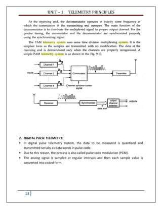
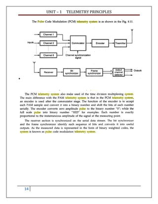
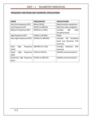
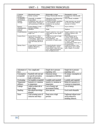
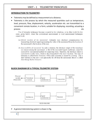
Telemetry is the process of measuring a physical quantity at a remote location and transmitting the data to a central station. This document discusses different types of telemetry systems based on transmission medium (wire, radio, optical fiber), modulation method (DC, AC, pulse), input signal (analog, digital), and number of channels (single, multi). It also describes specific systems including pneumatic, electrical, hydraulic, and pulse telemetry. Common frequency ranges used for telemetry applications are identified.
![UNIT – 1 TELEMETRY PRINCIPLES
8
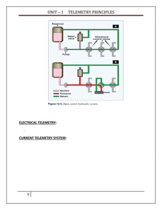
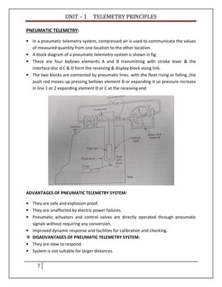
HYDRAULIC TELEMETRY:
• The open center system may employ any number of subsystems, with a selector valve
for each subsystem. Unlike the closed center system, the selector valves of the open
center system are always connected in series with each other. In this arrangement, the
system pressure line goes through each selector valve. Fluid is always allowed free
passage through each selector valve and back to the reservoir until one of the selector
valves is positioned to operate a mechanism. When one of the selector valves is
positioned to operate an actuating device, fluid is directed from the pump through one
of the working lines to the actuator. [Figure 12-3B] With the selector valve in this
position, the flow of fluid through the valve to the reservoir is blocked. The pressure
builds up in the system to overcome the resistance and moves the piston of the
actuating cylinder; fluid from the opposite end of the actuator returns to the selector
valve and flows back to the reservoir. Operation of the system following actuation of the
component depends on the type of selector valve being used. Several types of selector
valves are used in conjunction with the open center system. One type is both manually
engaged and manually disengaged. First, the valve is manually moved to an operating
position. Then, the actuating mechanism reaches the end of its operating cycle, and the
pump output continues until the system relief valve relieves the pressure. The relief
valve unseats and allows the fluid to flow back to the reservoir. The system pressure
remains at the relief valve set pressure until the selector valve is manually returned to
the neutral position. This action reopens the open center flow and allows the system
pressure to drop to line resistance pressure. The manually engaged and pressure
disengaged type of selector valve is similar to the valve previously discussed.
• When the actuating mechanism reaches the end of its cycle, the pressure continues to rise to a
predetermined pressure. The valve automatically returns to the neutral position and to open center flow](https://image.slidesharecdn.com/unit-1telemetryprinciples-180105115005/85/Unit-1-telemetry-principles-8-320.jpg)