Download to read offline

![b1 = 350;
b2 = 15020;
nump=[(m1+m2) b2 k2];
denp=[(m1*m2) (m1*(b1+b2))+(m2*b1)
(m1*(k1+k2))+(m2*k1)+(b1*b2) (b1*k2)+(b2*k1) k1*k2];
G1=tf(nump,denp);
num1=[-(m1*b2) -(m1*k2) 0 0];
den1=[(m1*m2)(m1*(b1+b2))+(m2*b1)(m1*(k1+k2))+(m2*k1)
+(b1*b2) (b1*k2)+(b2*k1) k1*k2];
G2=tf(num1,den1);
numf=num1;
denf=nump;
F=tf(numf,denf);
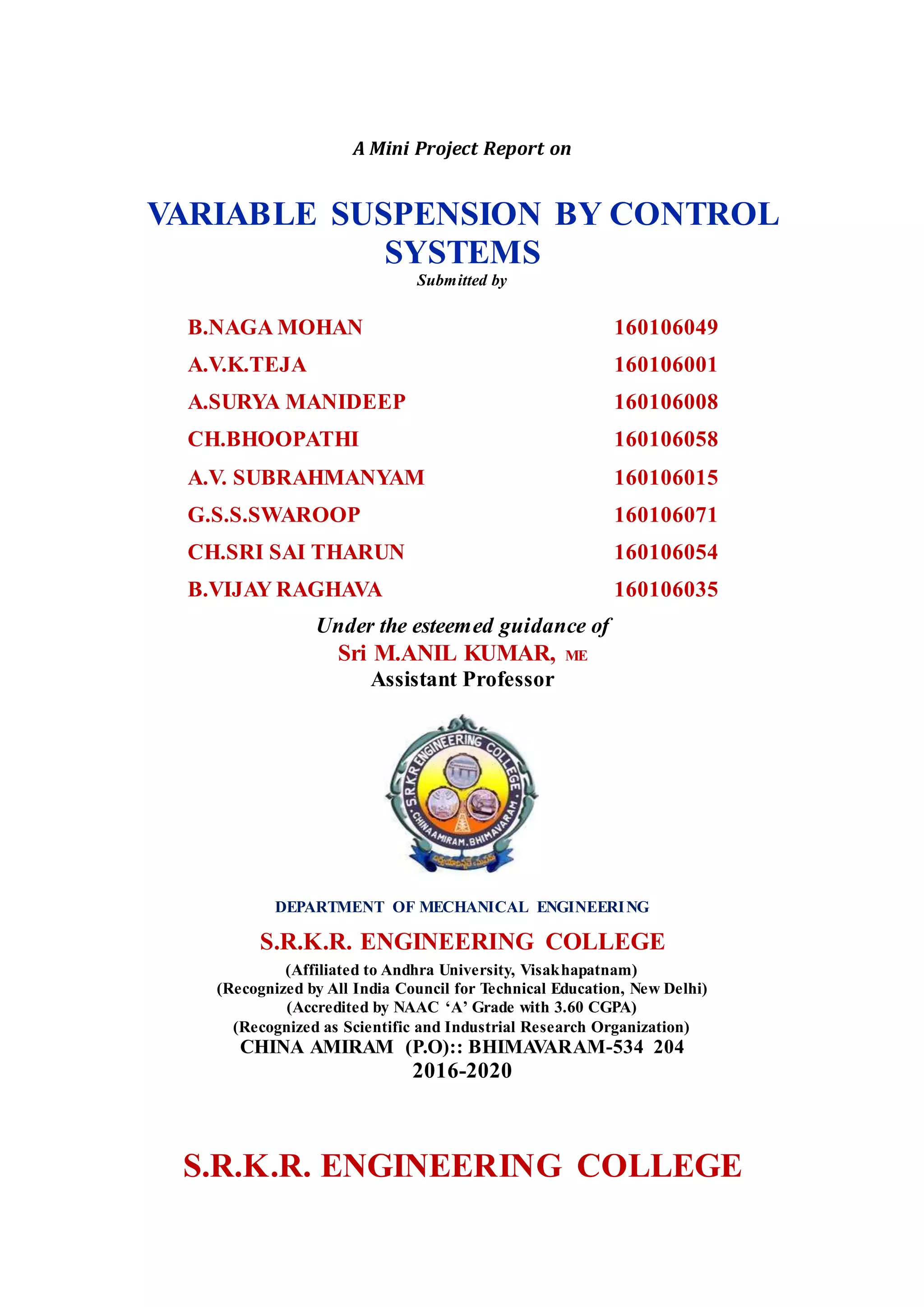
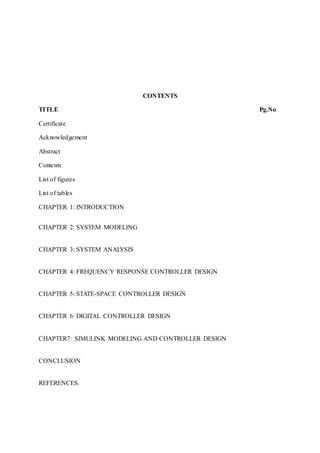
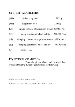
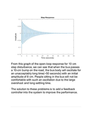
PLOTTING THE FREQUENCY RESPONSE IN MATLAB:
The main idea of frequency-
based design is to use the Bode plot of the open-loop transfer
function to estimate the closed-loop response. Adding a
controller to the system changes the open-loop Bode plot so that
the closed-loop response will also change. Let's first draw the
Bode plot for the original open-loop transfer function. Add the
following line of code to your m-file and rerun. You should get the
following Bode plot:
w = logspace(-1,2);](https://image.slidesharecdn.com/suspensioncontrollerdesignproject-210926024556/85/Suspensioncontrollerdesignproject-15-320.jpg)
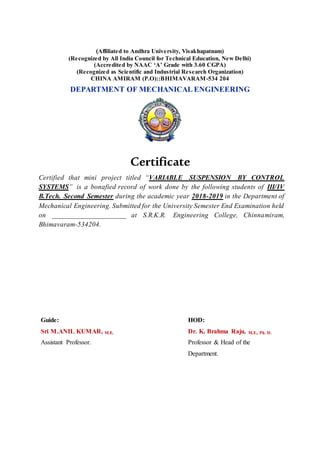
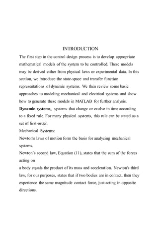
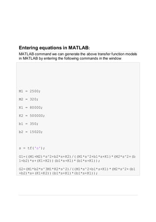
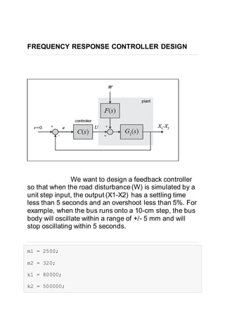
![ADDING LEAD CONTROL:
From the Bode plot above, we see that the phase curve is concave at
about 5 rad/sec.First, we will try to add positive phase around this region,
so that the phase will remain above the -180 degree line. Since a large
phase margin leads to a small overshoot, we will want to add at least 140
degrees of positive phase at the area near 5 rad/sec. Since one lead
controller can add no more than +90 degrees, we will use a two-lead
controller.
a = (1-sin(70/180*pi))/(1+sin(70/180*pi));
w=5;
T=1/(w*sqrt(a));
aT=sqrt(a)/w;
numc = conv([T 1], [T 1]);
denc = conv([aT 1], [aT 1]);
C = tf(numc,denc);
margin(K*C*G1)](https://image.slidesharecdn.com/suspensioncontrollerdesignproject-210926024556/85/Suspensioncontrollerdesignproject-17-320.jpg)
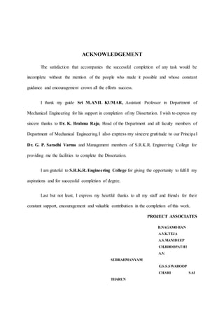
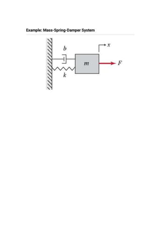
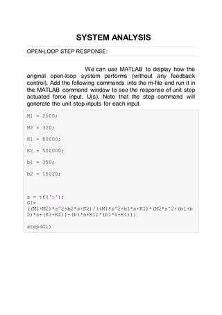
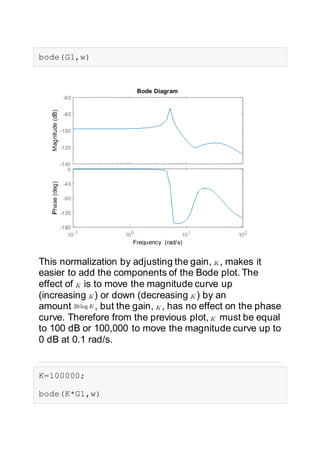
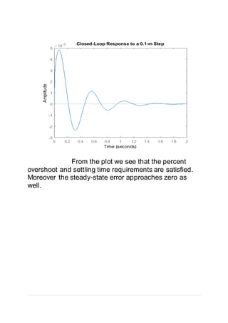
![PLOTTING THE CLOSED-LOOP RESPONSE:
Let's see what the step response looks like now. Keep in
mind that we are using a 0.1-m step as the disturbance. To simulate this,
simply multiply the system by 0.1. Add the following code into the m-file
and rerun it. Don't forget to put % mark in front of all bode and margin
commands!
t=0:0.01:5;
step(0.1*sys_cl,t)
axis([0 5 -.01 .01])](https://image.slidesharecdn.com/suspensioncontrollerdesignproject-210926024556/85/Suspensioncontrollerdesignproject-18-320.jpg)
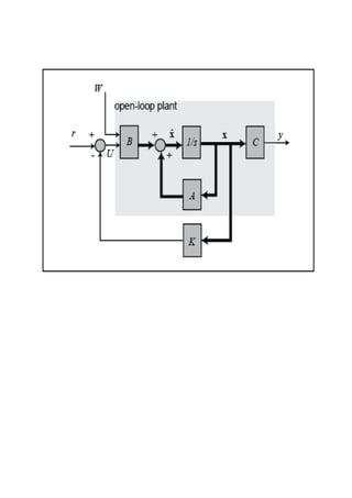
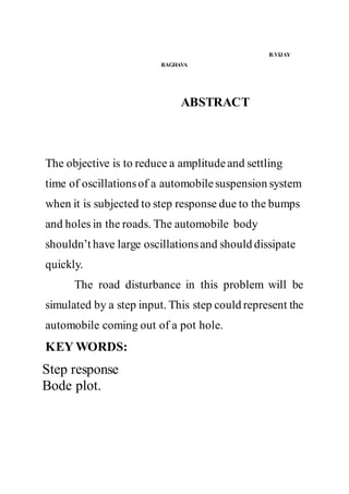
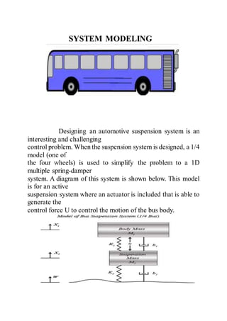
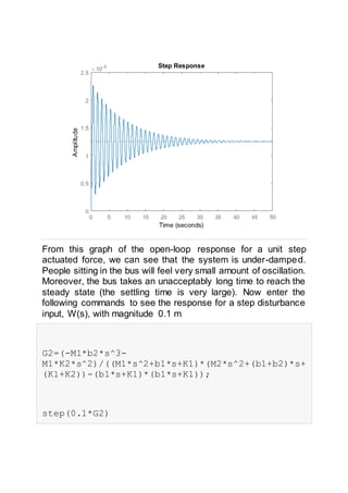
![The structure of the controller is similar
to the structure of the continuous-time state-space controller. We
will now use the place command to compute the gain matrix, K,
which will, in feedback, give us the desired closed-loop poles.
SIMULATING THE CLOSED-LOOP RESPONSE:
We can use the step command to
simulate the closed-loop response. Since multiplying the state
vector by K in our controller only returns a single signal, U, we
need to add a row of zeros to K by multiplying it by [1 0]'. This is
identical to what was done in the continuous design to
compensate for the fact that there are two inputs to the plant, but
only one is a control input. We will simulate with a negative 0.1-
m step disturbance in the road to give us a positive deflection of
the bus for aesthetic reasons
d_sys_cl = ss(Ad-Bd*[1;0]*K,Bd,Cd,Dd,T);
step(-.1*d_sys_cl*[0;1],5);](https://image.slidesharecdn.com/suspensioncontrollerdesignproject-210926024556/85/Suspensioncontrollerdesignproject-23-320.jpg)
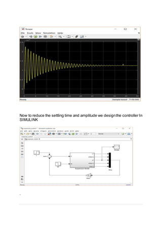
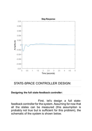
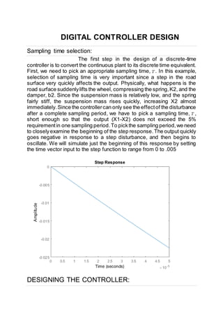
![Closed-loop response:
To simulate this system, first, an appropriate simulation time must be set.
Select Model Configuration Parameters from the Simulation menu and enter "2" in
the Stop Time field. The design requirements included a settling time of less than 5
sec, and the system actually settles in 2 sec. The physical parameters must now be
set. Run the following commands at the MATLAB prompt:
m1 = 2500;
m2 = 320;
k1 = 80000;
k2 = 500000;
b1 = 350;
b2 = 15020;
The last step is to assign values to the feedback gain matrix K. Execute the following command at the MATLAB
prompt.
K = [ 0 2.3e6 5e8 0 8e6 ];
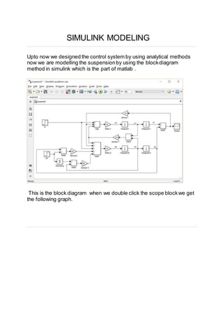
Run the simulation(Ctrl-T or Run from the Simulation menu).When the simulation is finished,double-click on the
Scope block and you should see the following output.
This
response agrees with the one found in state space controller design.](https://image.slidesharecdn.com/suspensioncontrollerdesignproject-210926024556/85/Suspensioncontrollerdesignproject-26-320.jpg)
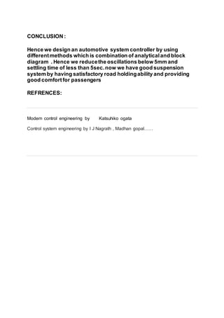

The document is a mini project report on 'Variable Suspension by Control Systems' submitted by mechanical engineering students at S.R.K.R. Engineering College. It outlines the objectives of reducing oscillations and settling time in automobile suspension systems, involving system modeling, analysis, and controller design using MATLAB. The project successfully demonstrates the design of an automotive suspension system controller achieving satisfactory performance metrics.


