Download to read offline
![International Research Journal of Engineering and Technology (IRJET) e-ISSN: 2395-0056
Volume: 06 Issue: 08 | Aug 2019 www.irjet.net p-ISSN: 2395-0072
© 2019, IRJET | Impact Factor value: 7.34 | ISO 9001:2008 Certified Journal | Page 1236
2.1 Plug-in Electric Vehicle Charger Topology
The desirable characteristics for the charger are power
bi-directionality (V2G and G2V), power factor equal to one,
capability of performing power control, low PQ impact,
construction and topology simplicity, and regular 16 A
single-phase plug compatibility. This charger does notallow
performing fast charge, being 2.3 kW (10 A, 230 V) the
advisable maximum power for a single-phase household-
type plug. This power range is defined based on EU
standards and power grid restrictions, since higher power
ranges could represent a negative impact on the low voltage
(LV) grid in terms of PQ and EMS requirements [22]–[24].
Regarding the voltage level of the battery pack,theproposed
design is focused on L-category vehicles (two-, three- and
four-wheel vehiclessuchasmotorcycles,mopeds,quads, and
minicars), as the one studied in [25], but could be extended
to other voltage levels.
Fig -3: PEV charger topology
The topology presented in Figure 3 is formed by three
legs of two Insulated Gate Bipolar Transistors (IGBT),
denoted by Sj ∈ {1, . . . , 6}. The IGBTs are used due to their
good compromise characteristics associated with voltage,
switching frequency and current limits. These power
switches are used for an AC/DC converter that operates as a
controlled rectifier or as an inverter for G2V or V2G
operation modes, respectively, and fora DC/DCconverter (C
class chopper) in which the power used for both modes is
restricted, as discussed below. The features of converters
meet the desired bi-directionality, where the chopper
operates as buck and boost for G2V and V2G operation
modes, respectively. Some passive elements forfiltering and
energy storage purposes are also designed and
implemented, which are relevant for achieving proper
system dynamics, stability and power quality.
3. CONTROLLERS DESIGN
The controllers are PI-based and they aim at properly
controlling the IGBT switching followingvoltageandcurrent
references.
For the chopper controller design, some assumptions were
made to facilitate circuit analysis: capacities in both sides of
the chopper are high enough for considering constant
voltage, low L capacity (when comparedtotheCbus capacity),
and negligible switching losses.
For establishing the control laws, it was necessary to
determine the differential equations describing the energy
demand of the converter (see (21)–(24)), according to
Kirchhoff laws. Typically, the state variables in the
converters are associated with the energy stored in
capacitors and inductors, leading to VCbus in the DC bus,
VBAT in the batteries, and IL in the chopper inductor as
displayed in Figure 4.
Fig -4: DC/DC converter controller architecture for V2G
and G2V operation modes
Fig -5: AC/DC converter controller architecture for V2G
and G2V operation modes.
The controller for the rectifier is also PI based. A daisy chain
of two PI controllers for DC bus voltage and AC current
regulation is used. For AC current regulation,a phase-locked
loop (PLL) is also used providing AC current control
reference as stated in [30]. This controller was firstly tuned
using a pole placement approach and then refined through
experimental tests, being the final IGBT PWM signal
provided by the unipolar PWM generator. The controller
used for the AC/DC converter when this works as inverter is
based only on the unipolar switching method. A unit
sinusoid reference provided by a PLL is used, which is
synchronized with the voltage grid. In this operation mode,
the DC bus available power was already restricted by the
chopper, being at this point only mandatoryinvertingthe DC
bus voltage in a proper way. Both AC/DC converter
controllers are presented in Figure 5.](https://image.slidesharecdn.com/irjet-v6i8282-191204083704/75/IRJET-Modeling-of-PV-based-Bidirectional-Battery-Charger-for-Electric-Vehicles-3-2048.jpg)
![International Research Journal of Engineering and Technology (IRJET) e-ISSN: 2395-0056
Volume: 06 Issue: 08 | Aug 2019 www.irjet.net p-ISSN: 2395-0072
© 2019, IRJET | Impact Factor value: 7.34 | ISO 9001:2008 Certified Journal | Page 1237
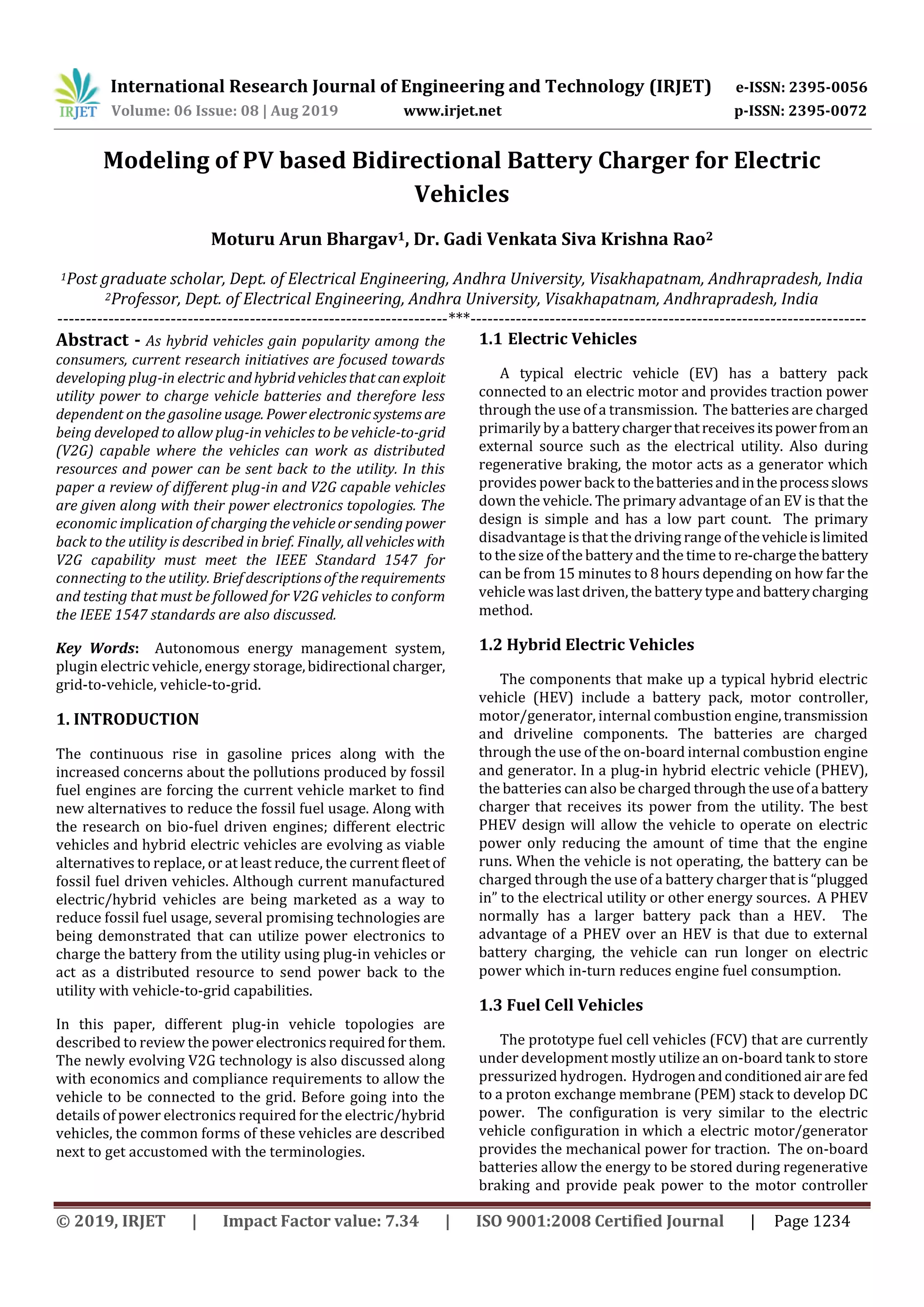
4. EXPERIMENTAL RESULTS
The experimental results have been obtained using a
reduced scale setup (with power levels 5 times lower than
the full scale). It is important to note that in this reduced
scale setup the DCBUS voltage was stabilized around 108 V
and Pmax was ±460W, being the “Advisable Energy Levels”
used for sizing, simulation and further full-scale
implementation. This setup uses theLEMHY25-PandLV 25-
P transducers for current and voltage acquisition,
respectively, as presented in Figs. 3 and 4. A DSP from NI for
control and data logging purpose is also used, jointly with
other laboratory equipment and several electronic
components, as presented in Fig. 6.
Fig -6: Simulation Diagram for PV based V2G System
Fig -7: Simulation Result for PV, Grid and Battery Powers
Fig -8: Simulation Result for DC Voltage and Current
Fig -9: Simulation Result for Inverter Voltage and Current
5. CONCLUSION
Use of power electronics can convert electric and hybrid
vehicles into plug-in or even V2G capable. With adequate
power conversion, a plug-in vehicle can be charged from
utility or a V2G capable vehicle can send power back to the
utility. With ever rising gas prices and with energy policy
thrust towards distributed resources, electric and hybrid
vehicle with plug-in and V2G capability will surely get
increased consumer and commercial attention in near
future. Currently,theNational RenewableEnergyLaboratory
(NREL) is reviewing various plug-in and V2G capable
vehicles and performing tests to verify utility connection
standards for these vehicles. The test results will be
published in future papers as soon as thetestingiscomplete.
6. REFERENCES
[1] Pacific Gas and Electric Company (PG&E) NewsRelease,
“Pacific Gas and Electric Company energizes silicon
valley with vehicle-to-grid technology,” April 2007.
[2] Electric Power Research Institute (EPRI) Report,
“Technology primer: the plug-in hybridelectricvehicle,”
pp. 1-2, 2007.
[3] T. Jahns and V. Blasko, “Recent advances in power
electronics technology for industrial and traction
machine drives,” Proc. of the IEEE, vol. 89, no. 6, pp. 963
– 975, June 2001.
[4] K. Wipke, S. Sprik, J. Kurtz, and H. Thomas, “Learning
demonstration progress report – September 2007,”
National Renewable Energy Laboratory Report, NREL
TP-560-42264, pp. 41, September 2007.
[5] K. Parks, P. Denholm, and T. Markel, “Costs and
emissions associated withplug-inhybridelectricvehicle
charging in the Xcel Energy Colorado service territory,”
National Renewable Energy Laboratory Report, NREL
TP-640-41410, pp. 29, May 2007.
[6] T. Markel, A. Brooker, J. Gonder, M. O'Keefe, A. Simpson,
and M. Thornton, “Plug-in hybrid vehicle analysis,” DOE
Milestone Report, NREL MP-540-40609, pp. 189,
November 2006.](https://image.slidesharecdn.com/irjet-v6i8282-191204083704/75/IRJET-Modeling-of-PV-based-Bidirectional-Battery-Charger-for-Electric-Vehicles-4-2048.jpg)
![International Research Journal of Engineering and Technology (IRJET) e-ISSN: 2395-0056
Volume: 06 Issue: 08 | Aug 2019 www.irjet.net p-ISSN: 2395-0072
© 2019, IRJET | Impact Factor value: 7.34 | ISO 9001:2008 Certified Journal | Page 1238
[7] W. Short and P. Denholm, “Preliminary assessment of
plug-in hybrid electric vehicles on wind energy
markets,” National Renewable Energy Laboratory
Report, NREL TP-620-39729, pp. 41, April 2006.
[8] J. Tomic and W. Kempton, “Using fleets of electric-drive
vehicles for grid support,” Elsevier J. of Power Sources,
vol. 168, no. 2, pp. 459– 468, June 2007.
[9] E. Hirst and B. Kirby, “What is system control,” Proc. of
American Power Conference, Chicago, IL, April 1999.
[10] B. Kirby, “Frequency regulation basics and trends,” Oak
Ridge National Laboratory Report, ORNL TM-2004-29,
pp. 32, December 2004.](https://image.slidesharecdn.com/irjet-v6i8282-191204083704/75/IRJET-Modeling-of-PV-based-Bidirectional-Battery-Charger-for-Electric-Vehicles-5-2048.jpg)

This document discusses modeling a photovoltaic (PV) based bidirectional battery charger system for electric vehicles. It begins with an introduction to electric vehicles, hybrid electric vehicles, and plug-in hybrid electric vehicles. It then discusses the topology and components of a typical plug-in electric vehicle charger, including a bidirectional DC/DC converter and AC/DC converter with controllers. Simulation results are presented showing the power flow between the PV panels, grid, and battery. The document concludes that power electronics can enable electric vehicles to charge from the grid or send power back, and that standards must be followed for vehicle-to-grid applications.