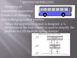
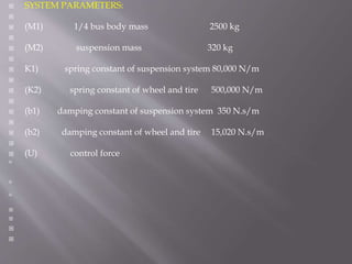
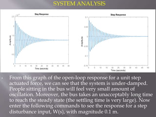
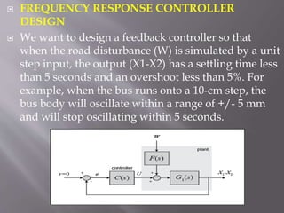
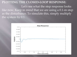
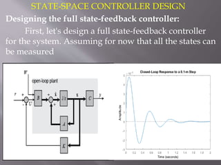
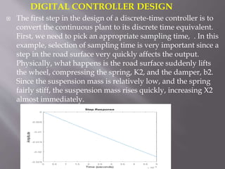
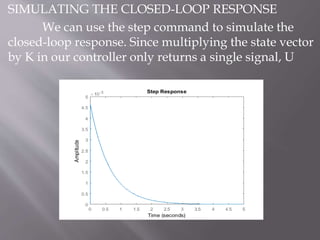
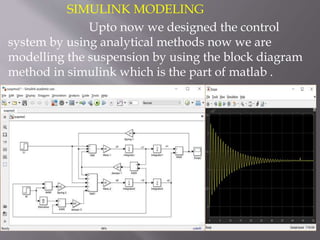
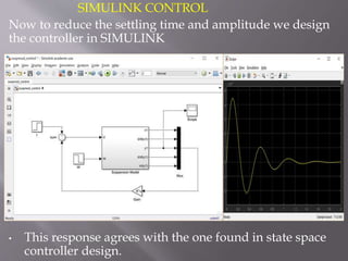
This document describes the design of a controller for an automobile suspension system using various control system methods. The objective is to reduce oscillations and settling time when the vehicle encounters bumps and potholes to improve passenger comfort. A quarter-car model is used to represent the system and analyze the open-loop response. Frequency response, state-space, and digital control design methods are applied to design controllers. Simulink modeling is also used to simulate the closed-loop response. The results show that the designed controllers reduce oscillations to below 5mm and settling time to less than 5 seconds, providing a satisfactory suspension system.
3. INRODUCTION
The objective is to reduce a amplitude and settling
time of oscillations of a automobile suspension
system when it is subjected to step response due to
the bumps and holes in the roads to feel human
comfort we designed controller by different control
system methods to get the optimum reduction in
amplitude and settling time .The automobile body
shouldn’t have large oscillations and should
dissipate quickly.
The road disturbance in this problem will be
simulated by a step input. This step could represent
the automobile coming out of a pot hole.
4. SYSTEM MODELLING
• Designing an
Automotive suspension
System is an intresting
and challenging control problem
• When the suspension system is designed a ¼
model(one of the four wheels) is used to simplify the
problem to a 1D multiple spring-damper
5. SYSTEM PARAMETERS:
(M1) 1/4 bus body mass 2500 kg
(M2) suspension mass 320 kg
K1) spring constant of suspension system 80,000 N/m
(K2) spring constant of wheel and tire 500,000 N/m
(b1) damping constant of suspension system 350 N.s/m
(b2) damping constant of wheel and tire 15,020 N.s/m
(U) control force
6. SYSTEM ANALYSIS
• From this graph of the open-loop response for a unit step
actuated force, we can see that the system is under-damped.
People sitting in the bus will feel very small amount of
oscillation. Moreover, the bus takes an unacceptably long time
to reach the steady state (the settling time is very large). Now
enter the following commands to see the response for a step
disturbance input, W(s), with magnitude 0.1 m.
7. FREQUENCY RESPONSE CONTROLLER
DESIGN
We want to design a feedback controller so that
when the road disturbance (W) is simulated by a unit
step input, the output (X1-X2) has a settling time less
than 5 seconds and an overshoot less than 5%. For
example, when the bus runs onto a 10-cm step, the
bus body will oscillate within a range of +/- 5 mm
and will stop oscillating within 5 seconds.
8. PLOTTING THE FREQUENCY RESPONSE IN
MATLAB:
The main idea of frequency-based design is to use the Bode
plot of the open-loop transfer function to estimate the closed-
loop response. Adding a controller to the system changes the
open-loop Bode plot so that the closed-loop response will also
change. Let's first draw the Bode plot for the original open-
loop transfer function.
9. This normalization by adjusting the gain, makes
it easier to add the components of the Bode plot. Theffect
of is to move the magnitude curve up (increasing ) or
down (decreasing ) by an amount , but the gain, has
no effect on the phase curve. Therefore from the
previous plot, must be equal to 100 dB or 100,000 to
move the magnitude curve up to 0 dB at 0.1 rad/s.
10. PLOTTING THE CLOSED-LOOP RESPONSE:
Let's see what the step response looks
like now. Keep in mind that we are using a 0.1-m step
as the disturbance. To simulate this, simply multiply
the system by 0.1.
11. STATE-SPACE CONTROLLER DESIGN
Designing the full state-feedback controller:
First, let's design a full state-feedback controller
for the system. Assuming for now that all the states can
be measured
12. DIGITAL CONTROLLER DESIGN
The first step in the design of a discrete-time controller is to
convert the continuous plant to its discrete time equivalent.
First, we need to pick an appropriate sampling time, . In this
example, selection of sampling time is very important since a
step in the road surface very quickly affects the output.
Physically, what happens is the road surface suddenly lifts
the wheel, compressing the spring, K2, and the damper, b2.
Since the suspension mass is relatively low, and the spring
fairly stiff, the suspension mass rises quickly, increasing X2
almost immediately.
13. SIMULATING THE CLOSED-LOOP RESPONSE
We can use the step command to simulate the
closed-loop response. Since multiplying the state vector
by K in our controller only returns a single signal, U
14. SIMULINK MODELING
Upto now we designed the control
system by using analytical methods now we are
modelling the suspension by using the block diagram
method in simulink which is the part of matlab .
15. SIMULINK CONTROL
Now to reduce the settling time and amplitude we design
the controller in SIMULINK
• This response agrees with the one found in state space
controller design.
16. CONCLUSION :
Hence we design an automotive system
controller by using different methods which is
combination of analytical and block diagram . Hence
we reduce the oscillations below 5mm and settling
time of less than 5sec. now we have good suspension
system by having satisfactory road holding ability and
providing good comfort for passengers .