This document outlines the design of the structural system for the Terra Santa School project in Jericho, Palestine. The school consists of three blocks designed using reinforced concrete. The document describes modeling the structure in SAP2000, analyzing seismic and gravity loads, and designing the structural elements including shear walls, columns, beams, and foundations according to code specifications. Analysis methods like response spectrum analysis and equivalent lateral force are used to design for seismic loads. Reinforcement is designed for various structural elements based on strength calculations.
Episode 39 : Hopper Design
Problem:
1 -experiments with shear box jenike on a particulate catalyst to give the family
yield locus as in 1. given that the bulk density is 1000 kg/m3 particulates and wall friction angle is 15
a-from design chart silo cone, do design a mass flow hopper for the material.
b-if the average size is 100 um, calculate the discharge flow rate passing through the discharge opening
2 - For the above materials using stainless steel is required to store 1000 tons of particulate in it. Coefficient of friction at the wall is given as 0.45 for each value and the formula that you use the appropriate justify the design.
a - draw the dimensions of the silo you and draw a vertical stress profile and the wall of the silo whole time say powerful particle
b- specify the maximum vertical stress and the wall of the silo you
c - if you use several different approaches in the design you provide appropriate recommendations to your employer for work before the end of the casting device fabrication started.
d - if problems such as the formation of the entrance are available after a certain time interval suggest measures - flow improvement measures to be taken to your employer
SAJJAD KHUDHUR ABBAS
Ceo , Founder & Head of SHacademy
Chemical Engineering , Al-Muthanna University, Iraq
Oil & Gas Safety and Health Professional – OSHACADEMY
Trainer of Trainers (TOT) - Canadian Center of Human
Development
Fire Resistance of Materials & Structures - Analysing the Steel StructureArshia Mousavi
A library room, whose structural steel members are to be checked in fire conditions (in terms of bearing capacity, R criterion).
The aims of this project are as follows:
1. Design of the beam and the column at room temperature
a) design the beam capacity at the ULS and the check the deflection at the SLS (d ≤ L1/250 in the rare combination) b) design the column for its buckling resistance.
2. Design the beam fire protection (boards) for the required fire resistance under the quasi-permanent load
the combination and assuming a three-sided exposure (concrete deck on top)
suggested steps: design load under fire
ultimate load of the beam at time = 0
ductility class
global failure or just a critical section?
increased capacity of the critical sections by the adaptation factors degree of utilization of the structure (or the critical section)
critical temperature.
protection design & final check.
3. Design the column fire protection
for the required fire resistance under the quasi- permanent load combination (optional: accounting for the effect of the thermal elongation of the beam).
suggested steps: design load under fire
thermal elongation of the beam assessment of the equivalent. uniform moment critical temperature (spreadsheet file)
protection design & final check
If needed, the member cross-sections designed at room temperature may be adjusted in order to meet the required fire resistance (parts 2 and 3)
As always I am pleased to post you an interesting presentation on Integrated Civil Engineering Design Coure. If you found it helpy you may make use of it. Please leave your feedbacks.
SUMMER INTERNSHIP REPORT at AMERIGO STRUCTURAL ENGINEERS PVT LTD,Mohit Kumar
This report has been prepared for the internship that has been done at Amerigo Structural Engineers PVT LTD, Bangalore in order to study the practical aspects of the course and implementation of the theory in the real field with the purpose of partially fulfilling the requirements of degree of Bachelor of Technology.
Ring or circular rafts can be used for cylindrical structures such as chimneys, silos, storage tanks, TV-towers and other structures. In this case, ring or circular raft is the best suitable foundation to the natural geometry of such structures. The design of circular rafts is quite similar to that of other rafts.
Honest Reviews of Tim Han LMA Course Program.pptxtimhan337
Personal development courses are widely available today, with each one promising life-changing outcomes. Tim Han’s Life Mastery Achievers (LMA) Course has drawn a lot of interest. In addition to offering my frank assessment of Success Insider’s LMA Course, this piece examines the course’s effects via a variety of Tim Han LMA course reviews and Success Insider comments.
Palestine last event orientationfvgnh .pptxRaedMohamed3
An EFL lesson about the current events in Palestine. It is intended to be for intermediate students who wish to increase their listening skills through a short lesson in power point.
A Strategic Approach: GenAI in EducationPeter Windle
Artificial Intelligence (AI) technologies such as Generative AI, Image Generators and Large Language Models have had a dramatic impact on teaching, learning and assessment over the past 18 months. The most immediate threat AI posed was to Academic Integrity with Higher Education Institutes (HEIs) focusing their efforts on combating the use of GenAI in assessment. Guidelines were developed for staff and students, policies put in place too. Innovative educators have forged paths in the use of Generative AI for teaching, learning and assessments leading to pockets of transformation springing up across HEIs, often with little or no top-down guidance, support or direction.
This Gasta posits a strategic approach to integrating AI into HEIs to prepare staff, students and the curriculum for an evolving world and workplace. We will highlight the advantages of working with these technologies beyond the realm of teaching, learning and assessment by considering prompt engineering skills, industry impact, curriculum changes, and the need for staff upskilling. In contrast, not engaging strategically with Generative AI poses risks, including falling behind peers, missed opportunities and failing to ensure our graduates remain employable. The rapid evolution of AI technologies necessitates a proactive and strategic approach if we are to remain relevant.
The Roman Empire A Historical Colossus.pdfkaushalkr1407
The Roman Empire, a vast and enduring power, stands as one of history's most remarkable civilizations, leaving an indelible imprint on the world. It emerged from the Roman Republic, transitioning into an imperial powerhouse under the leadership of Augustus Caesar in 27 BCE. This transformation marked the beginning of an era defined by unprecedented territorial expansion, architectural marvels, and profound cultural influence.
The empire's roots lie in the city of Rome, founded, according to legend, by Romulus in 753 BCE. Over centuries, Rome evolved from a small settlement to a formidable republic, characterized by a complex political system with elected officials and checks on power. However, internal strife, class conflicts, and military ambitions paved the way for the end of the Republic. Julius Caesar’s dictatorship and subsequent assassination in 44 BCE created a power vacuum, leading to a civil war. Octavian, later Augustus, emerged victorious, heralding the Roman Empire’s birth.
Under Augustus, the empire experienced the Pax Romana, a 200-year period of relative peace and stability. Augustus reformed the military, established efficient administrative systems, and initiated grand construction projects. The empire's borders expanded, encompassing territories from Britain to Egypt and from Spain to the Euphrates. Roman legions, renowned for their discipline and engineering prowess, secured and maintained these vast territories, building roads, fortifications, and cities that facilitated control and integration.
The Roman Empire’s society was hierarchical, with a rigid class system. At the top were the patricians, wealthy elites who held significant political power. Below them were the plebeians, free citizens with limited political influence, and the vast numbers of slaves who formed the backbone of the economy. The family unit was central, governed by the paterfamilias, the male head who held absolute authority.
Culturally, the Romans were eclectic, absorbing and adapting elements from the civilizations they encountered, particularly the Greeks. Roman art, literature, and philosophy reflected this synthesis, creating a rich cultural tapestry. Latin, the Roman language, became the lingua franca of the Western world, influencing numerous modern languages.
Roman architecture and engineering achievements were monumental. They perfected the arch, vault, and dome, constructing enduring structures like the Colosseum, Pantheon, and aqueducts. These engineering marvels not only showcased Roman ingenuity but also served practical purposes, from public entertainment to water supply.
Welcome to TechSoup New Member Orientation and Q&A (May 2024).pdfTechSoup
In this webinar you will learn how your organization can access TechSoup's wide variety of product discount and donation programs. From hardware to software, we'll give you a tour of the tools available to help your nonprofit with productivity, collaboration, financial management, donor tracking, security, and more.
Operation “Blue Star” is the only event in the history of Independent India where the state went into war with its own people. Even after about 40 years it is not clear if it was culmination of states anger over people of the region, a political game of power or start of dictatorial chapter in the democratic setup.
The people of Punjab felt alienated from main stream due to denial of their just demands during a long democratic struggle since independence. As it happen all over the word, it led to militant struggle with great loss of lives of military, police and civilian personnel. Killing of Indira Gandhi and massacre of innocent Sikhs in Delhi and other India cities was also associated with this movement.
Instructions for Submissions thorugh G- Classroom.pptxJheel Barad
This presentation provides a briefing on how to upload submissions and documents in Google Classroom. It was prepared as part of an orientation for new Sainik School in-service teacher trainees. As a training officer, my goal is to ensure that you are comfortable and proficient with this essential tool for managing assignments and fostering student engagement.
Instructions for Submissions thorugh G- Classroom.pptx
presentation1_28.pptx
1. An-Najah National University
Faculty of Engineering
Civil Engineering Department
Terra Santa School Structural Design and Analysis
Prepared By:
Bara Shawahna Khaled Malhis Nadeem AL-Masri
Supervised By : Dr. Mahmud Dwaikat
2. OUTLINE
Introduction & general description of the project
3D modeling
Shear walls design
Design of columns
Design of beams
Slabs design
Foundation design
3. INTRODUCTION
Our Graduation project is the design of a school in Jericho
named as Terra Santa School. This school was designed by
Al-Diyar Consultant and we will check on their design.
The school consists of three floors with total plan area of
(3866.5m2).
5. SAP 2000 program will be used as main analysis tool.
ACI 318-08 for design.
Live loads are taken from ASCE 7 -05 code.
UBC 97 for seismic design.
Methodology
6. MATERIALS USED IN THE PROJECT:
Reinforced concrete
The unit weight of concrete (𝛾) = 25 kN/m3.
The required compressive strength after 28 days
For slabs & beams fc is 25 MPa.
For Columns ,shear walls & footing fc is 30 MPa.
The yield steel bars required Fy = 420 MPa.
7. STRUCTURAL SYSTEMS
For each block we chose the following floor system:
1. Block A ( one way ribs slab )
2. Block B ( one way ribs slab )
3. Block C ( two way ribs slab )
Blocks A & B.
It’s very clear to see that block A , B has a uniform grid for columns with clear
path of loading (one-way), therefore, we took the architectural layout for the
columns. Ribbed slabs are known for their economic efficiency. The thickness
calculation follows the ACI-318 code
Block C.
Block C has a different shape and dimensions and according to ACI – code
requirements the slab should be designed as two-way ribbed slab for
economic and deflection requirements. This is because the spans of each
panel in Block C have approximately equal lengths.
8.
9. LOADS
Dead load:
Own weight for one way slabs = 3.54 kN/m2 .
Own weight for two way slabs = 4.86 kN/m2 .
Super imposed load = 3 kN/m2 .
Live load:
for all the class room = 2 KN/m2 .
for corridors = 5 KN/m2.
10. ANALYSIS AND DESIGN AGAINST SEISMIC
LOADS
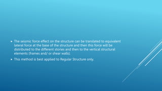
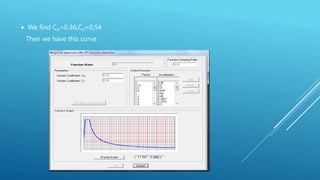
We will design the seismic load by using SAP2000. Several methods is
used in SAP for seismic which is:
Dynamic analysis:
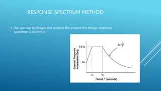
1. Response spectrum.
2. Time history.
Equivalent static force
Equivalent static method will be used for comparison [Block A only] and
as a cross-check on the results of response spectrum analysis. Because
response spectrum is more realistic and covers the modal shapes of the
building, we will use it as a main tool for seismic design.
11. The seismic force effect on the structure can be translated to equivalent
lateral force at the base of the structure and then this force will be
distributed to the different stories and then to the vertical structural
elements (frames and/ or shear walls).
This method is best applied to Regular Structure only.
12. DESIGN FOR EARTHQUAKE BY EQUIVALENT LATERAL FORCE
METHOD (STATIC METHOD) FOR BLOCK A
We will use the UBC97 method for analysis, because of available data and factors in
our region.
The total design base shear in a given direction shall be determined from the
following formula:
Where
𝑉 =
𝐶𝑣 𝐼
𝑅 𝑇
𝑤
1. Z= seismic zone factor.
2. I= importance factor.
3. R= Response Modification Factor
4. CV= velocity seismic coefficient.
5. W= the total dead load.
17. T CALCULATION
𝑇 = 𝐶𝑡(ℎ𝑛)
3
4
Hn= height of structure in meters = 15m
Ct = factor for this case =0.0488
T= is the basic natural period of a simple one degree of freedom
system which is the time required to complete one whole cycle during
dynamic loading.
And after calculation T=0.3719 sec, T from sap for block A =0.25 sec.
Difference can be due to presence of shear walls that increase the
stiffness of the building block.
18. Then calculate 𝑉 =
0.54𝑋1.25
5.5𝑋0.3719
× w = 0.33W
𝑉𝑚𝑖𝑛 = 0.11 𝑋 𝐶𝑎 𝑋 𝐼 𝑋 𝑊
Vmin. = 0.11X0.36 X1.25X w=0.0396W
Vmax=
2.5𝑋𝐶𝑎𝑋𝐼
𝑅
𝑊 0.2W
Vmax= 0.20 W use it because it Vcalculated>Vmax
For block A the weigh is = 12206 kN
V=0.20 X12206 =2441.2kN
From SAP Vtotal equivalent static force equal =2125kN.
From SAP Vtotal Response spectrum equal =1950kN.
19. RESPONSE SPECTRUM METHOD
We use sap to design and analyze the project the design response
spectrum is shown in
20. We find CA=0.36,CV=0.54
Then we have this curve
21. Then we should define a load cases in the X-direction, Y-direction, Z-
direction
When we define X-direction for example:
We scale factor is for X direction =
𝑔𝐼
𝑅
=
9.81𝑋1.25
5.6
= 2.227
And 33% of it for to the other direction Y = 0.33X2.227=0.7329 ( as per
UBC97 and ASCE requirements)
.
26. EQUILIBRIUM CHECK
FOR BLOCK A
Dead load:
1. Slab dead load = area X slab own weight per square meter =1185.84
X 3.54=4136.4 kN
2. Shear wall load = walls volume X concrete weight per volume = 28.7 X0.3
X15 X 25=3288.75 kN
3. Columns dead load = column volume X concrete weight per volume =
30 X 15 X0.4 X 0.4 X 25=1800 kN
4. Beams dead load = beams volume X concrete weight per volume =
3691.4 kN
5. Total dead load = 12917.6 kN
6. Total dead load form SAP = 12956.699
7. % Error = 0.3% which is acceptable
27. Live load:
Structure area X live load per square meter =1185.84 X 5 =5929.2 kN
Live load from SAP = 5929.2 kN
% Error = 0
Superimposed dead load:
Structure area X superimposed load per square meter = 1185.84 X 4.5
= 5336.28 kN
Superimposed load from SAP = 5336.2 kN
% Error = 0
28. MOMENT EQUILIBRIUM CHECK
We take block A as example to do this check. In this check we take the
moment from 3D modeling and find the weight and then comparing it
with the hand calculated weight
Moment resulted from dead load in block A in beam B1 is:
29. Calculating the moment =
39+44.75
2
+ 28.9 = 70.775 𝑘𝑁. 𝑚
𝑤×𝑙2
8
= 𝑀 ,
70.775×8
6.82 = 12.244
𝑘𝑁
𝑚
To convert it to kilo newton per square meter divide it over tributary
area which equal 3 meter
W = 4.08 kN/m2
Calculated dead load = 3.54 kN/m2.
% of error =
4.08−3.54
3.54
× 100% = 15%
Check for sway and non-sway:
∑𝑃𝑢 𝑋 𝐷𝑒𝑓𝑙𝑖𝑐𝑡𝑖𝑜𝑛
∑𝑉𝑢 𝑋 𝑙𝑖𝑛𝑔𝑡ℎ 𝑜𝑓 𝑐𝑜𝑙𝑢𝑚𝑛
< 0.05
361300
6068820
= 0.059
Its acceptable value. non-sway
30. DESIGN OF SHEAR WALLS
Design B2 in block B
axial force value Pu < 0.1 Ag fc
The maximum moment in the wall is 6824 kN.m
Assume singly reinforced section with reinforcement at d= 0.8h:
𝜌 =
0.85 𝑓𝑐
𝑓𝑦
1 − 1 −
2𝑀
0.85ᴓ𝑏𝑑2𝑓𝑐
=
0.85×30
420
1 − 1 −
2×6824×106
0.85×0.9×300×45002×30
= 3 × 10⁻³
𝐴𝑆 = 0.003 × 1000 × 300 =
900 𝑚𝑚2
𝑚
5∅16/𝑚
𝑉
𝑐 =
1
6
× 𝑓𝑐
′
× 𝑏𝑤 × 𝑑=0.1666𝑥 30𝑥300𝑥4500/1000 = 1233𝑘𝑁
Vu from sap =756 kN
𝑉
𝑛 =
𝑉𝑢
∅
, 𝑤ℎ𝑒𝑟𝑒 ∅ = 0.75
𝑉
𝑛 =
756
0.75
= 1008 𝑘𝑁
𝑉
𝑐 > 𝑉
𝑛 𝑢𝑠𝑒 𝑚𝑖𝑛𝑖𝑚𝑢𝑚 𝑠𝑡𝑒𝑒𝑙 =(1 ∅12/20𝑐𝑚)
32. DESIGN OF THE COLUMNS AGAINST SEISMIC
LOAD
Columns in Category C4(110X50)cm
We take the moment value from 3D –modal of
𝑀1
𝑀2
we have
𝑀1
𝑀2
=
312
298
= 1.04.
For the effective length factor (K) we take the building non sway so we
take k from φmajor= φ a=
𝐸𝑐𝐼𝑐/𝑙𝑐
𝐸𝑏𝐼𝑏/𝑙𝑏
= 12.4 , φ b=50 and φ minor=
𝐸𝑐𝐼𝑐/𝑙𝑐
𝐸𝑏𝐼𝑏/𝑙𝑏
=
11.99 and φ b=50the which is between equal 0.98 take it 1.
𝐾𝐿
𝑅
= 34 − 12
𝑀1
𝑀2
Check slenderness limit
1𝑋3000
0.3 ℎ
< 34 − 12
312
298
non-slender column
Using strength calculation, Pu<𝝫Pn for the same column, we got Ag =
5500000mm2. So the other dimension is5500000/500= 110mm. This
dimension should be larger or equal the least dimension so let it equal
500mm, so we took it equal to 500 mm
The dimension of column 110X50 cm so Ag= 5500cm2
Strength calculations for this column are done as follows:
33. From SAP2000 and 3D-model we take Pu=8287 and it equal 𝝫Pn then
we go to the interaction diagram and take the steel ratio value= 0.012
𝝫Pn/bh=15 =2.15 ksi
¥=h-2couver/h = 0.9
Mu/bh2=1.44 = 0.2 ksi
34. 𝑉
𝑐 =
1
6
× 𝑓𝑐
′
× 𝑏𝑤 × 𝑑 =⇒ 𝑉
𝑐 =
1
6
× 30 × 1100 × 460/1000 = 461.9 𝑘𝑁
𝑉
𝑛 =
𝑉
𝑢
∅
, 𝑤ℎ𝑒𝑟𝑒 ∅ = 0.75
𝑉
𝑛 =
88
0.75
= 117 𝑘𝑁
From SAP2000 the shear value on the column is equal 117 kN <463.9 it’s Ok
Since the column is not subjected to shear, we use minimum steel for shear reinforcement so as to hold vertical bars and
confine concrete.
The stirrup spacing must be the minimum of the following
•48 ds (diameter of stirrups)………..From code ACI 318-08
•16 db(diameter of bar) )………..From code ACI 318-08
•Least diminution of the section )………..From code ACI 318-08
•Not more than d/2……..From ACI 315-99
Therefore, use ᴓ10
•48 * 10 = 480 mm
•16 * 20= 320 mm
•500 mm
•460/2= 230 mm
Therefore use 4ᴓ10/150mm for stirrups along the column
38. FOR BEAM B1 AT BLOCK A UNDER SEISMIC LOAD
(50X35 CM)
39. 𝜌𝑚𝑖𝑛 = 𝑚𝑎𝑥
1.4
𝑓𝑦
,
0.25∗ 𝑓𝑐
𝑓𝑦
= 𝑚𝑎𝑥
0.00333,
0.00297
𝑢𝑠𝑒 𝜌𝑚𝑖𝑛 = 0.00333
For left span
Negative moment need 1284 mm2 (5𝝫20 mm).
For positive moment need 945 mm2 (4𝝫18 mm).
For the right span
Use (5𝝫20 mm) for top steel
And (4𝝫18 mm) for bottom steel
41. Near the column face
𝐴𝑣
𝑠
= 0.774
𝑠 =
157
0.774
= 200 𝑚𝑚
Use 1 𝝫 10 /100 mm
At the middle
𝐴𝑣
𝑠
= 0.292
S=500> S max
So use S max 230 mm
Use 1 𝝫 10 /150 mm
Right span
𝐴𝑣
𝑠
= 0.596
S= 263 mm > S max
Use 1 𝝫 10 /100mm
42.
43. SLAB DESIGN
The maximum span length is about 2.7m as shown in Block A,B Map,
and therefore the thickness of the slab (assumed one-way ribbed)
according to the table will be L /18.5 =15 cm and we used 20 cm for
block A& B(S1).
44. The maximum span length is about 7.55m as shown in Block C Map,
and therefore the thickness of the slab two-way ribbed according to the
table will be Ln /30 =25.1 cm and we used 30 cm.
45. For Slab S1 at block A (20 cm):
Slab S1 is one way ribbed slab with 9 spans 2.7m for each.
Dead and super imposed load = 8.04 kN/m2
Live load= 5kN/m2 due to corridor live load.
All 𝜌 value is less than 𝜌𝑚𝑖𝑛 so use 𝜌𝑚𝑖𝑛 for design.
Asmin = 𝜌𝑚𝑖𝑛 X bw X d= 0.0033X120X180=72mm .Used 2ᶲ10.(As bottom steel
46. Top rib steel
All 𝜌 value is less than 𝜌𝑚𝑖𝑛 so use 𝜌𝑚𝑖𝑛 for design.
Asmin = 𝜌𝑚𝑖𝑛 X bw X d= 0.0033X120X180=72mm .Used 2ᶲ10.
For Shrinkage net steel
Asmin = 𝜌𝑚𝑖𝑛 X b X d= 0.0018X1000X60=108mm2 Used 2ᶲ8
47. DESIGN FOR TWO WAY RIBBED SLAB IN BLOCK C
m11 (x-direction moment)
48. For left span the positive moment is
Mu =
86.4
(18.7−15.8)
= 29.8 𝑘𝑁. 𝑚
𝜌 =
0.85 𝑓𝑐
𝑓𝑦
1 − 1 −
2𝑀𝑢
0.85ᴓ𝑏𝑑2𝑓𝑐
= 0.0092
As = 𝜌 X bw X d= 0.0092X120X280=310 mm
Use 2𝝫16
For right span the positive moment is
Mu =
30
16.5−15.5
= 30 𝑘𝑁. 𝑚
𝜌 =
0.85 𝑓𝑐
𝑓𝑦
1 − 1 −
2𝑀𝑢
0.85ᴓ𝑏𝑑2𝑓𝑐
= 0.00928
As = 𝜌 X bw X d= 0.00928 X 120 X280= 310 mm
Use 2∅16
49. Design for negative moment (A-B section in x-direction)
Negative moment at the middle near the beam face.
Mu =
78
(16−14)
= 39 𝑘𝑁. 𝑚
𝜌 =
0.85 𝑓𝑐
𝑓𝑦
1 − 1 −
2𝑀𝑢
0.85ᴓ𝑏𝑑2𝑓𝑐
= 0.0125
As = 𝜌 X bw X d = 0.0125 X 120 X 280= 420 mm
Use 2𝝫20 (as top steel)
Negative moment at right edge
Mu =
60
(18−16)
= 30 𝑘𝑁. 𝑚
𝜌 =
0.85 𝑓𝑐
𝑓𝑦
1 − 1 −
2𝑀𝑢
0.85ᴓ𝑏𝑑2𝑓𝑐
= 0.00928
As = 𝜌 X bw X d = 0.00928 X 120 X 280= 312 mm
Use 2𝝫16 for both left and right edge (as top steel).
51. Design of F1 for C1
Pservice = 1200kN.
Pultimate=1500kN.
Bearing capacity= 250 kN/m2
Area of footing =
𝑆𝑢𝑟𝑣𝑖𝑐𝑒 𝑙𝑜𝑎𝑑
𝑝𝑒𝑎𝑟𝑖𝑛𝑔 𝑐𝑎𝑝𝑎𝑐𝑖𝑡𝑦
=
1200
250
= 4.8 m2
So we will use B= 2.2, L= 2.2
Footing long side (l)=
𝐿−𝐿 𝑐𝑜𝑙𝑢𝑚𝑛
2
=
2.2−0.4
2
=0.9m
58. the maximum moment is 238kN.m. in x-axis
𝜌 =
0.85 𝑓𝑐
𝑓𝑦
1 − 1 −
2𝑀
0.85ᴓ𝑏𝑑2𝑓𝑐
= 0.1%
𝜌 < 𝜌𝑚𝑖𝑛
Use 𝜌 = 0.0018
As = 0.0018×1000×800=1440 mm/m
the maximum moment is 414 kN.m in y-axis
T hen calculate 𝜌 =
0.85 𝑓𝑐
𝑓𝑦
1 − 1 −
2𝑀
0.85ᴓ𝑏𝑑2𝑓𝑐
= 0.173%
𝜌 < 𝜌𝑚𝑖𝑛
Use 𝜌 = 0.0018
As = 0.0018×1000×800=1440 mm/m
For shrinkage steel As = 0.5×0.0018×1000×800 =720 mm/m (5 𝝫14 mm / m).