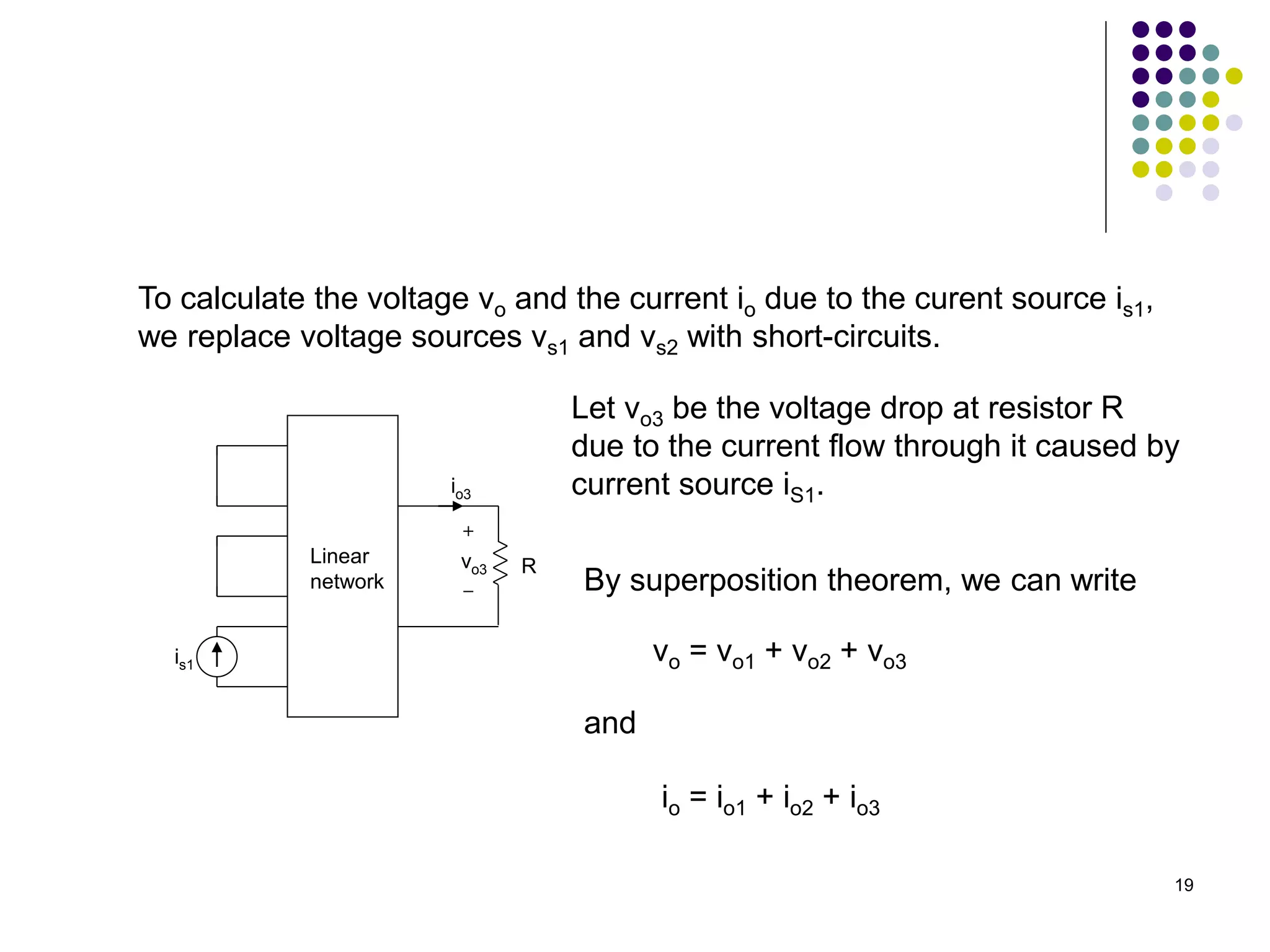
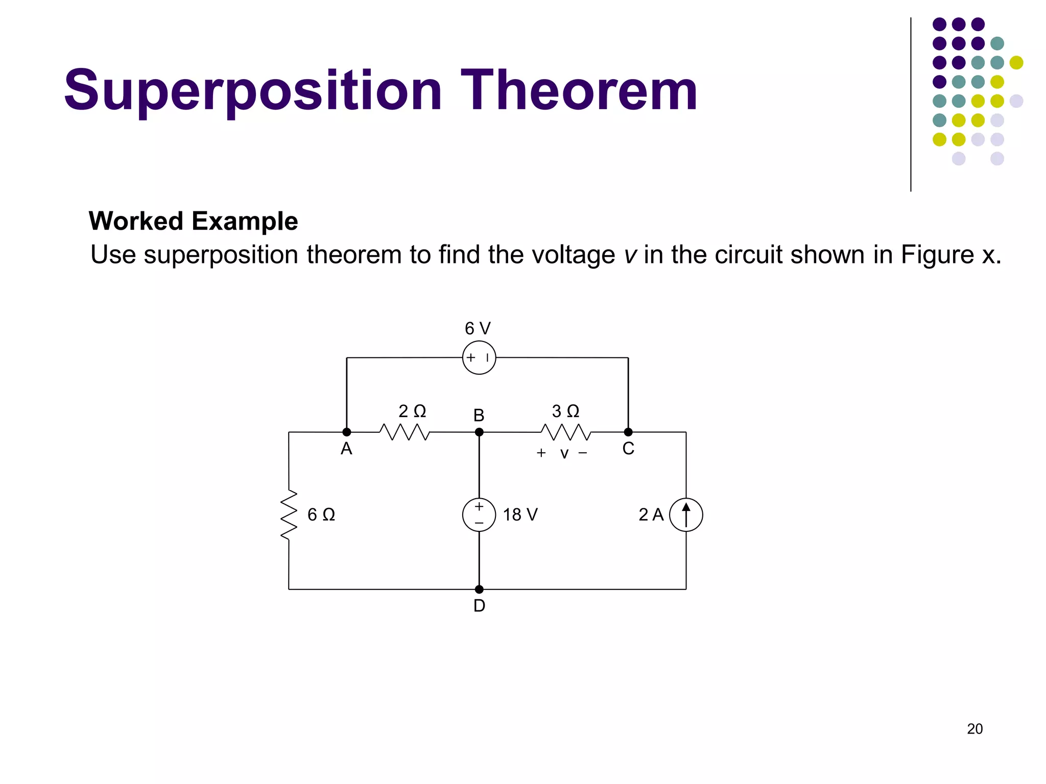
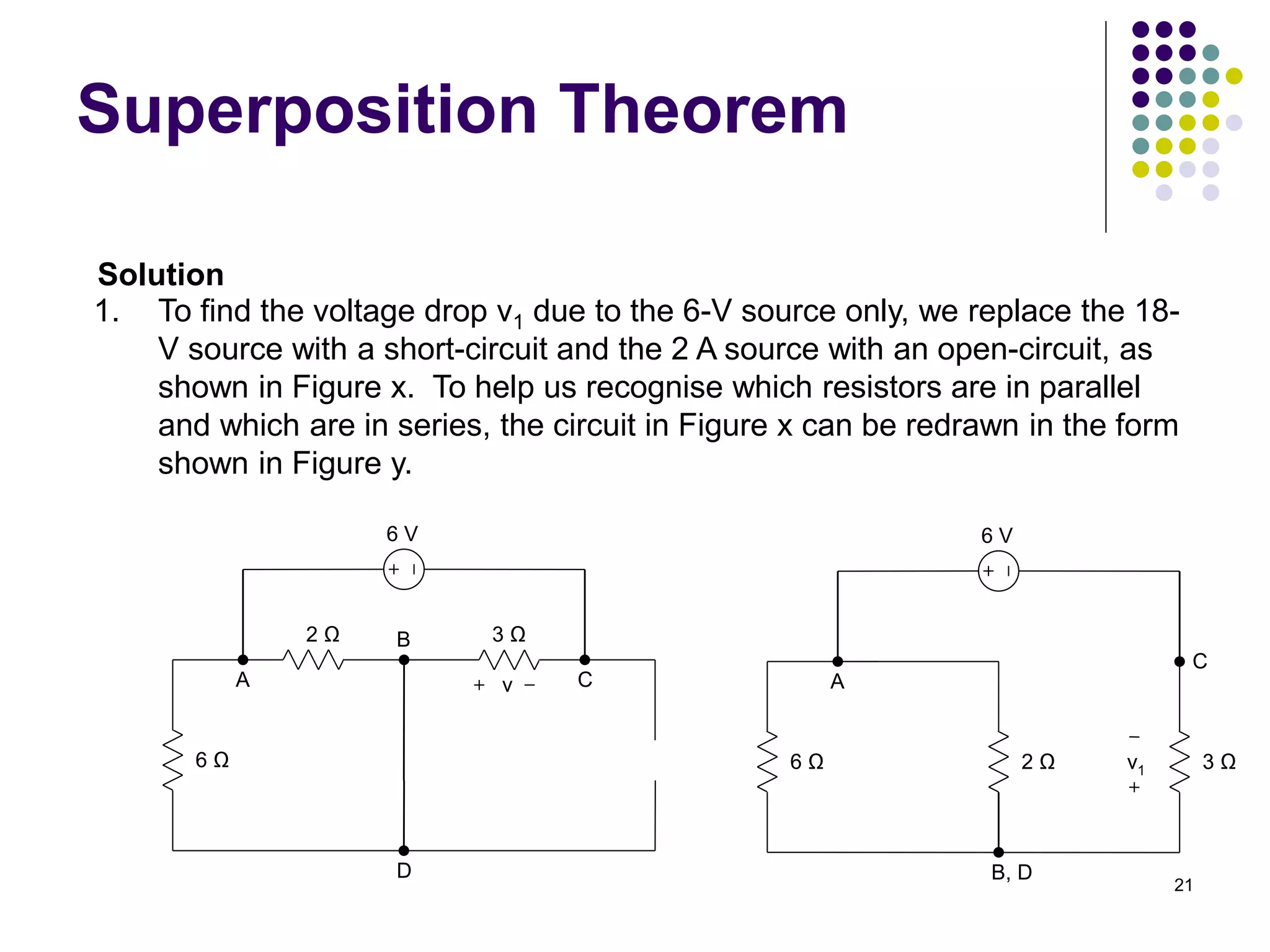
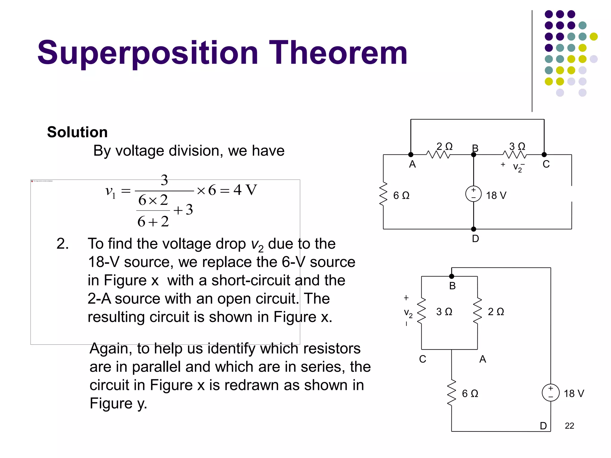
This document discusses linear circuits and techniques for analyzing them, including linearity principle, superposition theorem, and source transformations. It provides examples of using linearity principle to find unknown voltages and currents when an independent source is applied to a linear network. It also provides examples of using superposition theorem to solve for unknowns in a linear circuit with multiple independent sources by considering each source individually.
![14
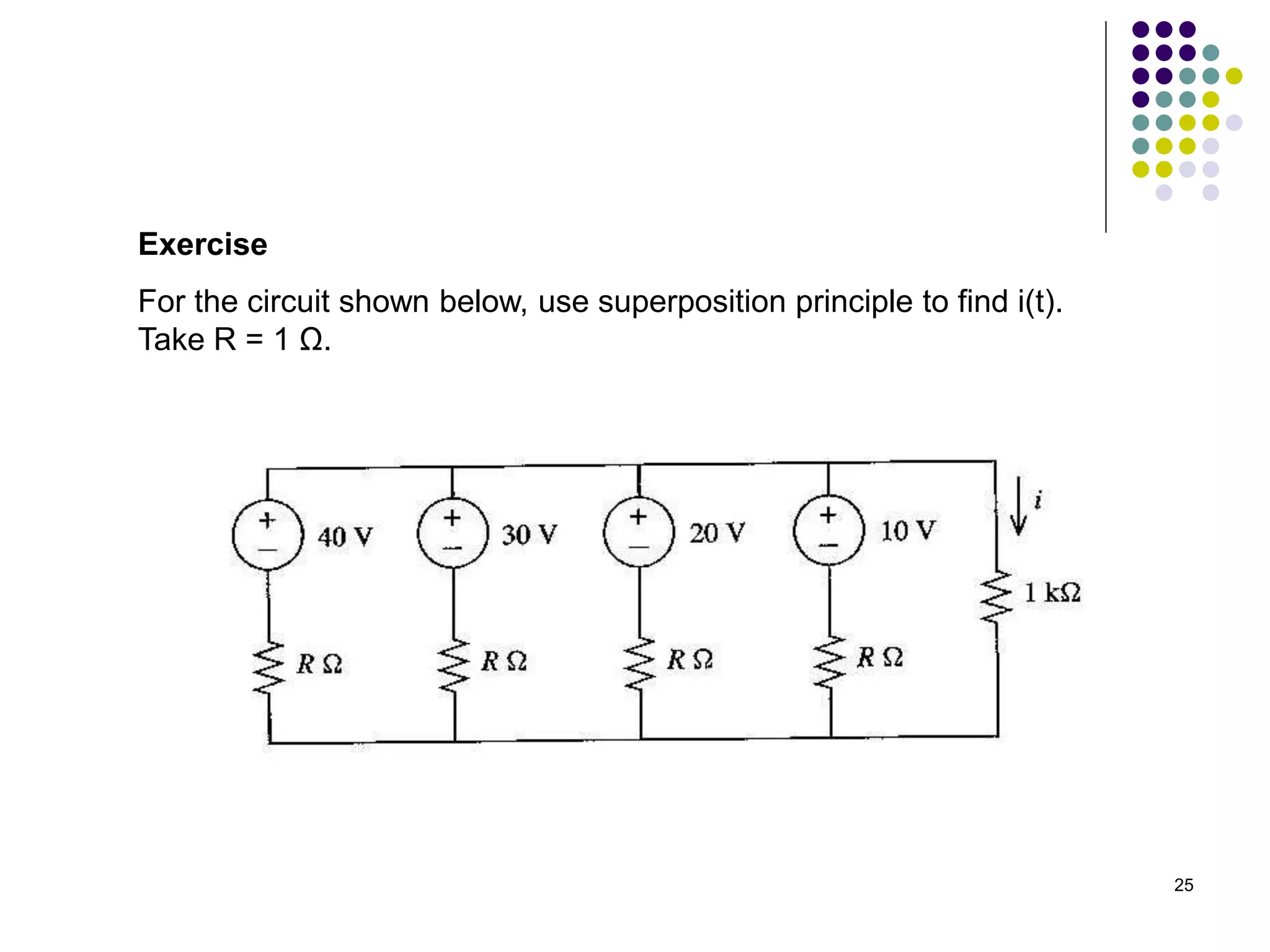
Exercise
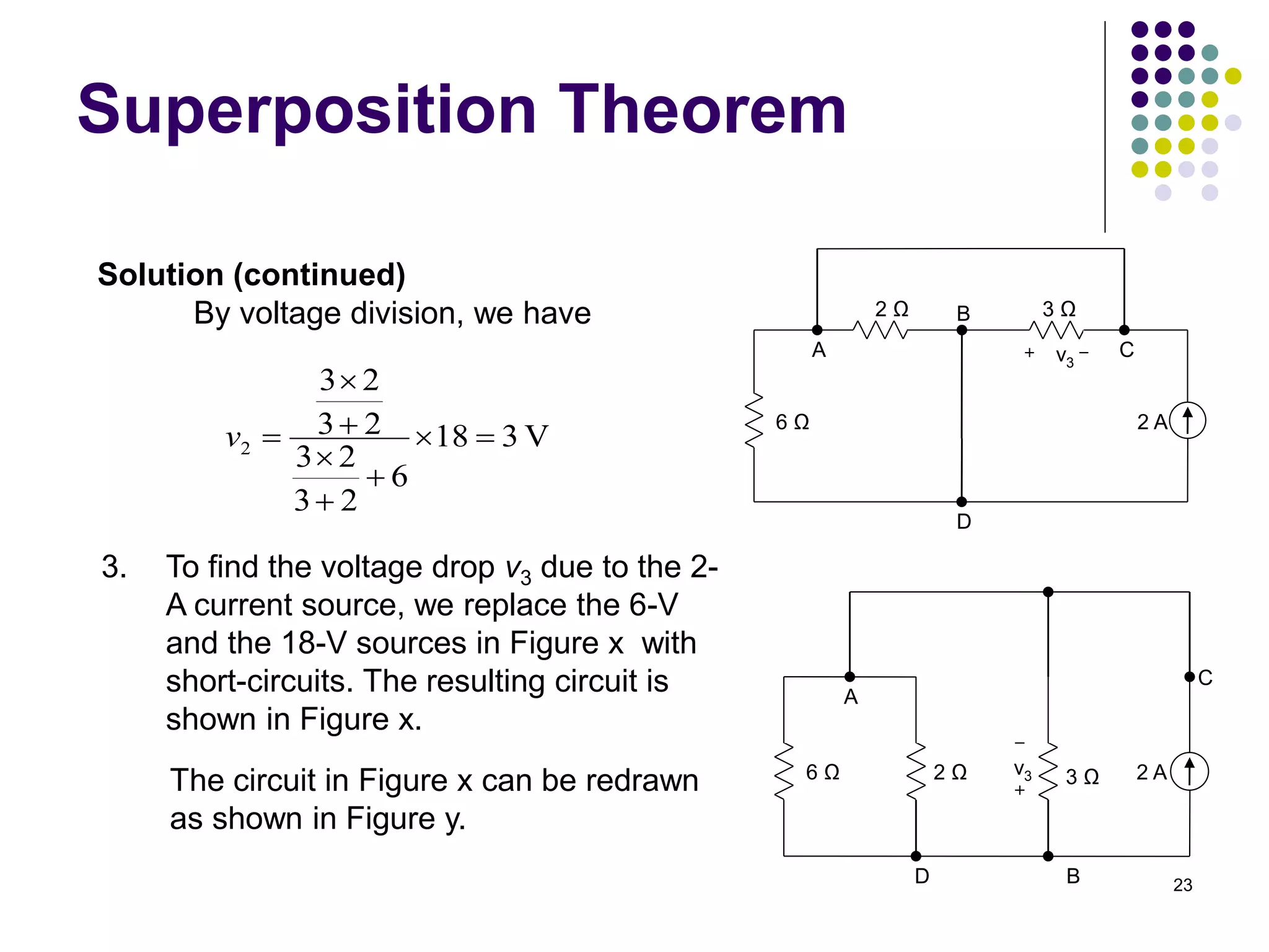
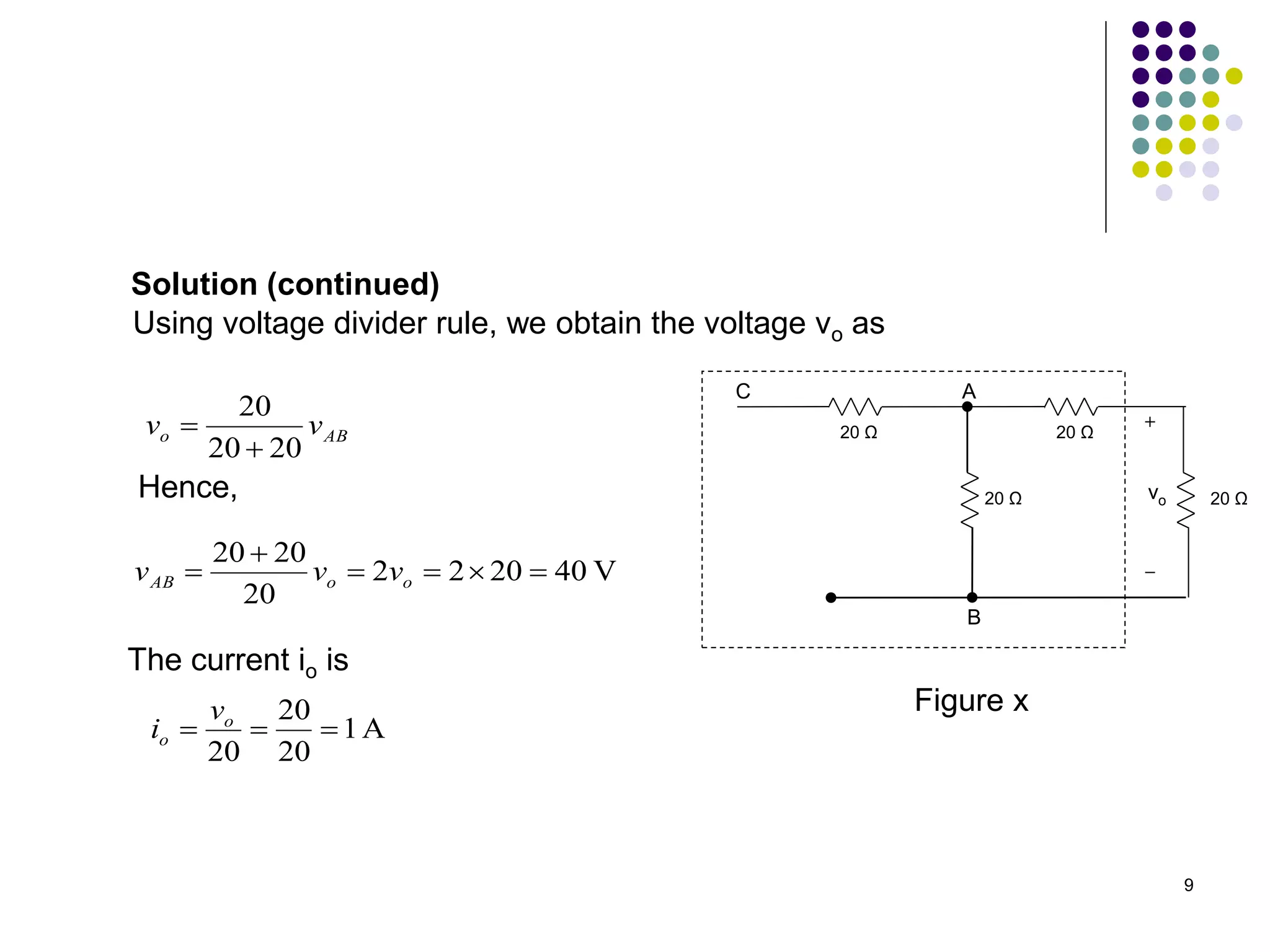
Use the proportionality principle to obtain the voltage vo.
1 Ω
0.5 Ω
3 Ω
vo
E = 10 V 5 Ω 1 Ω
A
B
C
D
E
F
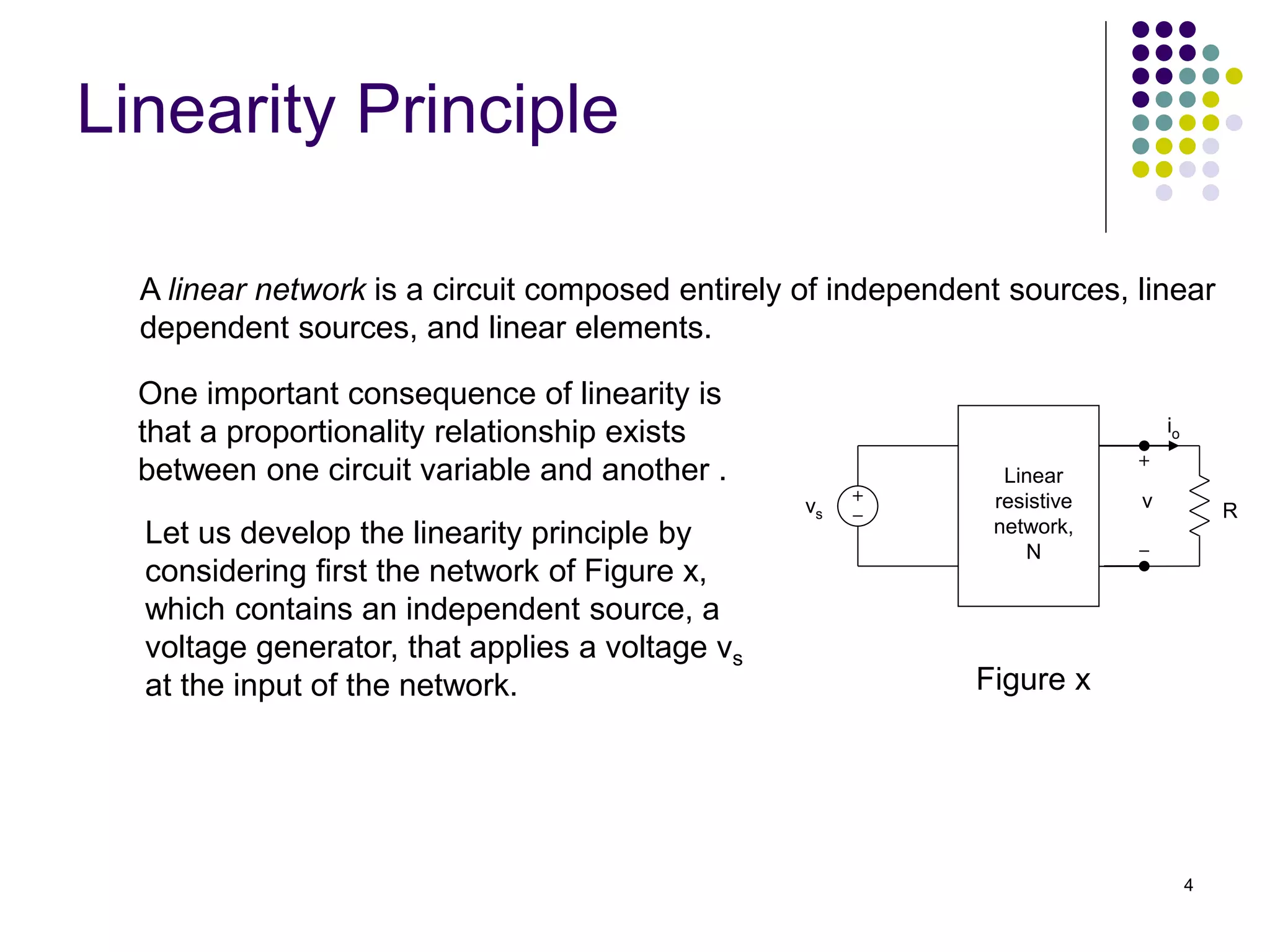
Figure x
[ Ans: vo = 3 V ]](https://image.slidesharecdn.com/bef12403-week7-linearityandsuperpositionprinciples-230622062257-9338d2eb/75/BEF-12403-Week-7-Linearity-and-Superposition-Principles-ppt-14-2048.jpg)