Downloaded 918 times
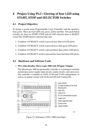
![References
[1] Richard A. Cox, ”Technicians Guide to Programmable Controllers” , 4th
edition, Vikash Publishing House, New Delhi.
[2] J. R. Hackworth, F.D. Hackworth, ”Programmable Logic Controllers Pro-gramming
Methods and Applications” Pearson Education, New Delhi
[3] J. W. Webb, R A Reis , ”Programmable Logic Controllers Principle and
Applications” 5th edition, Prentice Hall of India ltd., New Delhi
[4] literature.rockwellautomation.com/idc/groups
33](https://image.slidesharecdn.com/plc-141120033808-conversion-gate02/85/Plc-and-scada-report-39-320.jpg)

This document is a training report submitted by Indira Kundu to her faculty supervisor, Ms. Pushpa Gothwal, on PLC and SCADA systems. It includes an introduction to automation and PLCs, describing their components, operation, and uses of ladder logic programming. It also covers SCADA systems, their features and applications. The document details two student projects using PLC and SCADA to control LEDs and model a sewage treatment system respectively.


