SlideShare a Scribd company logo
1 of 168
Download to read offline
1 Application Solutions Guide — The Global Combined Cycle Landscape
REFINERY
PROCESS
Application Solutions Guide
Experience In Motion
DECEMBER 2019
2 Application Solutions Guide — Refinery Process
TABLE OF CONTENTS
GLOBAL REFINERY LANDSCAPE .  .  .  .  .  .  .  .  .  .  .  . 6
Market Overview.  .  .  .  .  .  .  .  .  .  .  .  .  .  .  .  .  .  .  .  .  .  .  .  . 6
		 Nelson Refinery Complexity.  .  .  .  .  .  .  .  .  .  .  .  . 8
		 The Equivalent Distillation Capacity.  .  .  .  .  .  . 8
		 Refinery Crude Terminology. .  .  .  .  .  .  .  .  .  .  .  . 8
		 American Petroleum Institute Terminology. . 9
		 Examples of Industry Standards .  .  .  .  .  .  .  .  . 9
		 Refinery Process Overview .  .  .  .  .  .  .  .  .  .  .  . 11
A CLOSER LOOK AT
REFINERY PROCESSES
. .  .  .  .  .  .  .  .  .  .  .  .  .  .  .  .  .  .  . 15
Cut Points.  .  .  .  .  .  .  .  .  .  .  .  .  .  .  .  .  .  .  .  .  .  .  .  .  .  .  .  . 15
		FCC .  .  .  .  .  .  .  .  .  .  .  .  .  .  .  .  .  .  .  .  .  .  .  .  .  .  .  .  .  . 15
		Hydrocracker.  .  .  .  .  .  .  .  .  .  .  .  .  .  .  .  .  .  .  .  .  .  . 16
		 Ebullated Bed Hydrocracker .  .  .  .  .  .  .  .  .  .  . 16
		Naphtha Fractions .  .  .  .  .  .  .  .  .  .  .  .  .  .  .  .  .  .  . 16
		 LPG and Gas Fractions .  .  .  .  .  .  .  .  .  .  .  .  .  .  . 17
		Hydrotreating.  .  .  .  .  .  .  .  .  .  .  .  .  .  .  .  .  .  .  .  .  .  . 17
Refinery Conversion.  .  .  .  .  .  .  .  .  .  .  .  .  .  .  .  .  .  .  .  . 18
		Conversion Processes.  .  .  .  .  .  .  .  .  .  .  .  .  .  .  . 19
Hydrogen Plant.  .  .  .  .  .  .  .  .  .  .  .  .  .  .  .  .  .  .  .  .  .  .  .  . 20
Desalter .  .  .  .  .  .  .  .  .  .  .  .  .  .  .  .  .  .  .  .  .  .  .  .  .  .  .  .  .  . 20
Nitrogen Plant.  .  .  .  .  .  .  .  .  .  .  .  .  .  .  .  .  .  .  .  .  .  .  .  .  . 20
Amine Treating .  .  .  .  .  .  .  .  .  .  .  .  .  .  .  .  .  .  .  .  .  .  .  .  . 20
Sulphur Recovery.  .  .  .  .  .  .  .  .  .  .  .  .  .  .  .  .  .  .  .  .  .  . 20
Asphalt Plant. .  .  .  .  .  .  .  .  .  .  .  .  .  .  .  .  .  .  .  .  .  .  .  .  .  . 20
Feed Stock and Gases, Key Processes
and Finished Product PFD.  .  .  .  .  .  .  .  .  .  .  .  .  .  .  . 21
Critical Pump and Valve
Products by Process. .  .  .  .  .  .  .  .  .  .  .  .  .  .  .  .  .  .  .  . 22
		Flowserve Pumps.  .  .  .  .  .  .  .  .  .  .  .  .  .  .  .  .  .  .  . 22
		 Slurry Oil Pump
. .  .  .  .  .  .  .  .  .  .  .  .  .  .  .  .  .  .  .  .  . 23
		 Feed Charge Pump .  .  .  .  .  .  .  .  .  .  .  .  .  .  .  .  .  . 23
		 Reactor and Recycle Pumps. .  .  .  .  .  .  .  .  .  . 24
		Decoking Pumps.  .  .  .  .  .  .  .  .  .  .  .  .  .  .  .  .  .  .  . 24
		 Coker Heater Charge.  .  .  .  .  .  .  .  .  .  .  .  .  .  .  .  . 24
		Jet Pump .  .  .  .  .  .  .  .  .  .  .  .  .  .  .  .  .  .  .  .  .  .  .  .  .  . 25
		 Bottom Unheading Flowserve Valve
. .  .  .  .  . 25
		 Decoking Control Valve .  .  .  .  .  .  .  .  .  .  .  .  .  .  . 25
		Alkylation Pumps.  .  .  .  .  .  .  .  .  .  .  .  .  .  .  .  .  .  .  . 26
		Hydrotreater Pumps.  .  .  .  .  .  .  .  .  .  .  .  .  .  .  .  .  . 26
		Amine Pumps.  .  .  .  .  .  .  .  .  .  .  .  .  .  .  .  .  .  .  .  .  .  . 26
		 Specialized Vacuum Pumps. .  .  .  .  .  .  .  .  .  .  . 27
3 Application Solutions Guide — Refinery Process
TABLE OF CONTENTS (CONTINUED)
KEY REFINERY PROCESSES
WITH EQUIPMENT
. .  .  .  .  .  .  .  .  .  .  .  .  .  .  .  .  .  .  .  .  .  .  .  . 28
Atmospheric Distillation Detailed Process .  .  .  . 28
		 Sample of Atmospheric
		 Distillation Application Conditions .  .  .  .  .  .  . 32
Vacuum Distillation Detailed Process.  .  .  .  .  .  .  . 34
		 Recommended Control Valve
		 Features for Vacuum Distillation.  .  .  .  .  .  .  .  . 37
Delayed Coking Detailed Process .  .  .  .  .  .  .  .  .  . 38
		 Delayed Coker Unit Overview .  .  .  .  .  .  .  .  .  . 38
		Application Guides. .  .  .  .  .  .  .  .  .  .  .  .  .  .  .  .  .  . 40
		 DCU System Overview. .  .  .  .  .  .  .  .  .  .  .  .  .  .  . 41
		 Pioneers in Decoking Pumps.  .  .  .  .  .  .  .  .  .  . 44
Hydrotreater Detailed Process.  .  .  .  .  .  .  .  .  .  .  .  . 46
		 Hydrotreater Process Description
. .  .  .  .  .  .  . 51
		Critical Pumps .  .  .  .  .  .  .  .  .  .  .  .  .  .  .  .  .  .  .  .  .  . 52
		 Fluid Catalytic Cracking Detailed Process . . 53
		 FCC Process Description.  .  .  .  .  .  .  .  .  .  .  .  .  . 57
		 FCC Centrifugal Pumps.  .  .  .  .  .  .  .  .  .  .  .  .  .  . 58
		 Fluid Catalytic Cracking
		Power Recovery.  .  .  .  .  .  .  .  .  .  .  .  .  .  .  .  .  .  .  .  . 58
		 Critical FCC Pumps and Valves.  .  .  .  .  .  .  .  . 60
Hydrocracker Detailed Process .  .  .  .  .  .  .  .  .  .  .  . 63
		Process Description.  .  .  .  .  .  .  .  .  .  .  .  .  .  .  .  .  . 67
		Critical Pumps .  .  .  .  .  .  .  .  .  .  .  .  .  .  .  .  .  .  .  .  .  . 69
		Special Note.  .  .  .  .  .  .  .  .  .  .  .  .  .  .  .  .  .  .  .  .  .  .  . 72
Catalytic Reformer .  .  .  .  .  .  .  .  .  .  .  .  .  .  .  .  .  .  .  .  .  . 73
		 Why Is This Process So
		 Important to Flowserve?.  .  .  .  .  .  .  .  .  .  .  .  .  .  . 74
		Process Description.  .  .  .  .  .  .  .  .  .  .  .  .  .  .  .  .  . 75
		 Catalytic Reformer Unit
. .  .  .  .  .  .  .  .  .  .  .  .  .  .  . 76
Isomerization
. .  .  .  .  .  .  .  .  .  .  .  .  .  .  .  .  .  .  .  .  .  .  .  .  .  . 80
		 Isomerization in the Refinery Process .  .  .  . 80
Alkylation (Hydrofluoric) .  .  .  .  .  .  .  .  .  .  .  .  .  .  .  .  .  . 82
		Alkylation Application.  .  .  .  .  .  .  .  .  .  .  .  .  .  .  .  . 83
Vapor Recovery Unit.  .  .  .  .  .  .  .  .  .  .  .  .  .  .  .  .  .  .  .  . 85
		 Vacuum or Flue and
		 Flare Gas Applications.  .  .  .  .  .  .  .  .  .  .  .  .  .  .  . 86
Auxiliary (Power House).  .  .  .  .  .  .  .  .  .  .  .  .  .  .  .  .  . 89
		 Steam and Power.  .  .  .  .  .  .  .  .  .  .  .  .  .  .  .  .  .  .  . 89
Tank Farms, Blending (Mixing) and Off-Sites. . 89
		 Tankage and Blending.  .  .  .  .  .  .  .  .  .  .  .  .  .  .  . 89
		 Off-Sites and Wastewater.  .  .  .  .  .  .  .  .  .  .  .  .  . 89
Hydrodesulphurization
. .  .  .  .  .  .  .  .  .  .  .  .  .  .  .  .  .  .  .  .  .  . 92
Amine Treating Unit
. .  .  .  .  .  .  .  .  .  .  .  .  .  .  .  .  .  .  .  .  . 93
Sulfur Recovery Unit.  .  .  .  .  .  .  .  .  .  .  .  .  .  .  .  .  .  .  .  . 95
		Centrifugal Pumps.  .  .  .  .  .  .  .  .  .  .  .  .  .  .  .  .  .  . 95
		Application Review. .  .  .  .  .  .  .  .  .  .  .  .  .  .  .  .  .  . 95
Asphalt Plant. .  .  .  .  .  .  .  .  .  .  .  .  .  .  .  .  .  .  .  .  .  .  .  .  .  . 96
4 Application Solutions Guide — Refinery Process
TABLE OF CONTENTS (CONTINUED)
GLOBAL REFINERY LANDSCAPE .  .  .  .  .  .  .  .  .  .  . 97
Business Impact and Focus Areas.  .  .  .  .  .  .  .  .  . 97
Products for Refinery — At a Glance.  .  .  .  .  .  .  . 99
		Industry-Leading Brands.  .  .  .  .  .  .  .  .  .  .  .  .  . 99
		Pump Types.  .  .  .  .  .  .  .  .  .  .  .  .  .  .  .  .  .  .  .  .  .  . 100
		 Block Valve Types
. .  .  .  .  .  .  .  .  .  .  .  .  .  .  .  .  .  . 119
		Ball Valves .  .  .  .  .  .  .  .  .  .  .  .  .  .  .  .  .  .  .  .  .  .  .  . 119
		Plug Valves.  .  .  .  .  .  .  .  .  .  .  .  .  .  .  .  .  .  .  .  .  .  .  . 119
		Butterfly Valves. .  .  .  .  .  .  .  .  .  .  .  .  .  .  .  .  .  .  .  . 119
		Actuators .  .  .  .  .  .  .  .  .  .  .  .  .  .  .  .  .  .  .  .  .  .  .  .  . 126
		 Control Valves Types .  .  .  .  .  .  .  .  .  .  .  .  .  .  .  . 135
		 Typical Flowserve Control Valves.  .  .  .  .  .  . 136
		 Seals and System Types .  .  .  .  .  .  .  .  .  .  .  .  . 139
		 Seal System Piping Plans. .  .  .  .  .  .  .  .  .  .  .  . 144
AFTERMARKET PARTS AND
SERVICES IN REFINERIES
. .  .  .  .  .  .  .  .  .  .  .  .  .  .  .  . 146
Mechanical Upgrades and Retrofits.  .  .  .  .  .  .  . 146
LifeCycle Management Programs
. .  .  .  .  .  .  .  .  . 147
Educational and Consultative Services
. .  .  .  .  . 147
Replacement Parts and
Component Offerings.  .  .  .  .  .  .  .  .  .  .  .  .  .  .  .  .  .  . 148
		 Standard OEM Replacement
		 Parts and Components
. .  .  .  .  .  .  .  .  .  .  .  .  .  . 148
		Parts Programs. .  .  .  .  .  .  .  .  .  .  .  .  .  .  .  .  .  .  .  . 148
		 Quick Response Programs
. .  .  .  .  .  .  .  .  .  .  . 148
		Rapid Prototyping. .  .  .  .  .  .  .  .  .  .  .  .  .  .  .  .  .  . 149
		Equipment Performance. .  .  .  .  .  .  .  .  .  .  .  .  . 149
		Strategic Procurement.  .  .  .  .  .  .  .  .  .  .  .  .  .  . 149
		Streamlined Inventory. .  .  .  .  .  .  .  .  .  .  .  .  .  .  . 150
		Technical Support .  .  .  .  .  .  .  .  .  .  .  .  .  .  .  .  .  . 150
		 Tools and Technology
. .  .  .  .  .  .  .  .  .  .  .  .  .  .  . 150
Large Capital Project Support. . . . . . . . . . . . 152
Quick-Ship Products.  .  .  .  .  .  .  .  .  .  .  .  .  .  .  .  .  .  .  . 152
Upgrade Programs.  .  .  .  .  .  .  .  .  .  .  .  .  .  .  .  .  .  .  .  . 153
		RVX Upgrade.  .  .  .  .  .  .  .  .  .  .  .  .  .  .  .  .  .  .  .  .  . 153
INSTALLATIONS AND EXPERIENCE .  .  .  .  .  .  .  . 156
Preferred Supplier Agreements
. .  .  .  .  .  .  .  .  .  .  . 156
		 Trusted Experience Across
		 the Oil and Gas Industry. . . . . . . . . . . . . 157
		Global Accounts. .  .  .  .  .  .  .  .  .  .  .  .  .  .  .  .  .  .  . 157
5 Application Solutions Guide — Refinery Process
TABLE OF CONTENTS (CONTINUED)
COMMUNICATING OUR VALUE. .  .  .  .  .  .  .  .  .  .  .  . 158
Flowserve Value Proposition
for Refineries. .  .  .  .  .  .  .  .  .  .  .  .  .  .  .  .  .  .  .  .  .  .  .  .  . 158
Innovative Ways Flowserve
Addresses Customer Challenges.  .  .  .  .  .  .  .  .  . 159
Business Pain Points and Opportunities. .  .  .  . 160
		 Flowserve Meets the
		Customers’ Challenges .  .  .  .  .  .  .  .  .  .  .  .  .  . 160
		 Business Pains and Challenges.  .  .  .  .  .  .  . 160
		Typical User Challenges
		 With Valves in the Processes.  .  .  .  .  .  .  .  .  . 163
		Hydrocracking Process
		 Challenges on Pumps and Valves.  .  .  .  .  . 164
		 Solutions for Challenges in
		Hydrocracker Installations .  .  .  .  .  .  .  .  .  .  .  . 165
Value Proposition Summary:
Why Flowserve? .  .  .  .  .  .  .  .  .  .  .  .  .  .  .  .  .  .  .  .  .  .  . 167
		 Industry-Leading Products and
		 Services in Refinery Processes.  .  .  .  .  .  .  . 167
6 Application Solutions Guide — Refinery Process
GLOBAL REFINERY LANDSCAPE
Market Overview
Modern refineries are complex facilities, processing
products into a number of various specifications.
Refineries are designed or enhanced to make a
wide variety of products: gasoline, fuel oil, lube
oils, jet/condensates, solvents, diesels, asphalts,
coke and gases/LPGs. An average refinery size is
between 100 000 to 400 000 BPD. For the purposes
of this guide, all our estimates and references are
for 200 000 BPD refineries.
The composition of crude oils varies significantly,
depending upon their source.
Refineries are complex systems with multiple
operations.
• The basics of all refineries are the same, but the
specific operations vary and depend on:
–Properties of the crude oil refined
–Desired finished product output
Table 1.1: Refining process
CRUDE OIL
▼
REFINERY
Light Fuels
Natural Gas (Methane)
Ethane/Propane
Liquefied Propane &
Butane
▼
Chemicals
Benzene
Ethylbenzene
Xylene
▼
Liquid Fuels
Gasoline
Diesel
Kerosene
Jet Fuel & Naphtha
▼
Lubes
Lube Oils
Grease
▼
Residuals
Residual Fuel
Asphalt
▼
Ethylene Plants
Propylene Plants
Chemical Plants
▼
Chemical Plants
▼
Consumer Uses
Chemical Plants
Ethylene Plants
Propylene
▼
Consumer and
Industrial Users
▼
Industrial Users
Roads, etc.
▼
Polyethylene
Polypropylene
Nylon
Styrene
Polyester
Gasoline
Jet Fuels
Diesel
Heating Oil
Motor Oil
Grease
Heating Oil
Bunker C
Asphalt
Roofing Material
7 Application Solutions Guide — Refinery Process
GLOBAL REFINERY LANDSCAPE
refineries are geared toward specific products
or are smaller in size. In this regard, refinery
operations are predicated on the performance of
the mechanical equipment, e.g., pumps, valves,
blowers, compressors, drivers and seal systems.
The application of these products is key to be
properly sized and designed for satisfactory MTBF.
Equipment such as pumps and valves usually
represent 10% to 15% of the capital investment in
the refinery processes; they are the most important
type of equipment with respect to plant reliability.
Twenty-first-century technologies have improved
to make the processes more efficient, steam
and cracking less risky, and MTBF longer for
maintenance/shutdown schedules. Shale gas has
become an alternative to naphtha as the feed stock
to petrochemical sites due to low cost feed stock
(specifically in North America) but more important,
the electronic monitoring and controls for safety,
process improvements and life cycle costs. Today’s
CONVERSION
SEPARATION STORAGE AND BLENDING
Crude
Gasoline
Gas
Naphtha
Kerosene
Fuel Oil
Residual/Asphalt
Separation Crude Oil into
Various Fractions Based
on Boiling Point
• Crude Desalter
• Atmosphere Crude Unit
• Vacuum Crude Unit
Converts Lower Value
Products into High-Demand,
Premium Products
• Residual Conversion
• Middle Distillate Upgrading
• Light Ends Processing
Combines the Various
Components from the
Conversion Processes
into End-Use Products
BLENDING
Figure 1.1: Basic refinery process flow
8 Application Solutions Guide — Refinery Process
Nelson Refinery Complexity (NCI)
Allows comparison between different types of refineries.
• Simple “hydroskimming” refineries may only separate and treat
• Complex “hydrocracking” refineries will also have several conversion processes
The Nelson complexity index (NCI) is a measure to compare the secondary conversion capacity of a
petroleum refinery with the primary distillation capacity. The index provides an easy metric for quantifying
and ranking the complexity of various refineries and units. To calculate the index, it is necessary to use
complexity factors, which compare the cost of upgrading units to the cost of crude distillation unit.
The Equivalent Distillation Capacity (EDC)
• Each unit is assigned a complexity index based on cost relative to the atmospheric crude unit
• The sum of the unit complexities normalized to the atmospheric distillation capacity
Refinery Crude Terminology
API (American Petroleum Institute) gravity crude
oil is classified as light, medium or heavy, according
to its measured API gravity.
• Light crude oil is defined as having
an API gravity higher than 31.1° API
• Medium oil is defined as having an API
gravity between 22.3° API and 31.1° API
• Heavy oil is defined as having an API
gravity below 22.3° API
1 barrel equals 42 U.S. gallons
1 BPD = Gallons / (hrs*min) = 42 / (24*60) = .0292 gpm
1 gpm = 34.29 BPD
1 barrel equals 158.984 liters
The approximate conversion for BPD to tonnes/year
is 49.8, so 100 000 BPD equals around 4 980 000
tonnes per year.
Crude oil has virtually no value in its raw form.
Value is added by refining it into sellable fuels and
chemical (Naphtha & Ethane) feed stocks.
GLOBAL REFINERY LANDSCAPE
Table 1.3: Circa 2014
Table 1.2: Generalized complexity indices
Refining Process Generalized complexity index
Atmospheric distillation 1
Vacuum distillation 2
Delayed coking 6
Visbreaking 2 .75
Catalytic cracking 6
Catalytic reforming 5
Catalytic hydrocracking 6
Catalytic hydrorefining 3
Refining Process Generalized complexity index
Catalytic hydrotreating 2
Alkylation/polymerization 10
Aromatics/isomerization 15
Lubes 10
Asphalt 1.5
Hydrogen (MCFD) 1
Oxygenates MTBE 10
Holland US China Russia
# Refineries 6 125 54 40
Crude M B/D 1197 17 788 6866 5431
Complexity 7.85 9.62 2.26 4.56
EDC ME B/D 9336 171 190 15 551 24 785
9 Application Solutions Guide — Refinery Process
Category 1
(ASME B73.1)
Type A
(Pusher)
Type B
(Bellows)
Type C
(High Temp Bellows)
Arrangement 1
(Single)
Arrangement 2
(Unpressurized Dual)
Arrangement 3
(Pressurized Dual)
Category 1
(API 610)
• Pump Type
• Seal Type
• Arrangement
Examples of Industry Standards
GLOBAL REFINERY LANDSCAPE
Figure 1.3: API 682 for seals
Figure 1.2: API 610 for pumps
American Petroleum Institute (API) Terminology
The oil and gas industry uses a series of specifications for pumps, seals, systems and valves.
These specifications and guides provide standards used globally, which all manufacturers are directly
involved, and have committees established to define everything from scope of product types to vibrations,
materials and test standards.
10 Application Solutions Guide — Refinery Process
GLOBAL REFINERY LANDSCAPE
Figure 1.4: In-process refinery end products and finished marketable refinery end products diagram
API for valves
The oil and gas industry does not use a universal API specification for valves like they have on pumps and
seal systems; however, there are a few specs written, to which are often referred.
1-ANSI: 1610/1634, which are more dimensional guides
2-NACE: specs for metallurgy
11 Application Solutions Guide — Refinery Process
GLOBAL REFINERY LANDSCAPE
Refinery Process Overview
The feedstock of crude oil is a gooey mixture of various hydrocarbons which is de-salted, heated, separated and
broken down big molecules of un-useable heavy product into smaller molecules of useable lighter products. The
heavier products are fed into catalytic cracking or hydrocracking units to obtain gasoline, naphtha and middle
distillates. Catalysts are used to improve the yield of the gasoline and lighter products in the cracker. A catalyst
is a substance which facilitates a chemical reaction without being consumed in the reaction. Hydrocracking
is similar, but done in an atmosphere of hydrogen (second key feed stock to a refinery). The hydrogenation
increases the yield of gasoline and produces saturated hydrocarbons which do not gum up with time.
Hydrogen sites are not always directly located at a refinery, but are key feedstock to several processes within
the refinery.
Hydrotreating or reforming improves the quality of finished products and can require several treaters in a
refinery based on the various products broken down after distillation. Hydrotreating stabilizes as saturated non-
gumming molecules and with reforming, re-arranges the structure to improve to high-octane aromatics.
Naphtha is processed and used in gasoline and solvents, and continues to be key today as the feedstock for
petrochemical or polyethylene crackers in chemical plants. However, in the past decade, shale gas which is a
primary product of ethane is also a key, and growing feedstock to the petrochemical industry.
The wet gas from the fractionated units in the vapor recovery splits into fuel gas, LPG, butane, isobutane and
unsaturated hydrocarbons.
Fuel gas is used in refinery heaters. Butane gets blended into LPG or gasoline, and the unsaturated
hydrocarbons along with isobutene are sent to the alkylation unit for conversion into high-octane compounds to
be blended into jet fuel and premium gasoline.
An alky unit uses sulfuric or hydrofluoric acid as the catalyst to react to unsaturated hydrocarbons with
isobutene to form high-octane isoparaffins compounds.			
Off-Sites
Superintendent
Area 1
• Crude • Vacuum
• Coke • Visbreaker
Area 2
•Alkylation
• FCCU
•Gas Plant
•Hydrocracker
Area 3
•Reformer •Utilities
•Hydrotreater •SRU
Blending
Movement
Dock &
Terminals
Purchasing/Supply
Process Engineering
Project Engineering
I & E
Process
Mechanical
Drafting
Off-Sites
Superintendent
Technical
Services
Design
Maintenance
Safety
Planning/
Scheduling
Vice President—Refining
Refinery Manager
Operations Manager Engineering Manager
Figure 1.5: Refinery management and
process owner’s organization example
Customers expect the equipment suppliers they prefer to have a vast understanding of the refinery
operations, i.e., what is expected of the processes in which the equipment is applied and the
overall process scheme. More important is the support on tough services.
GLOBAL REFINERY LANDSCAPE
Figure 1.6: Refining process diagram
Figure 1.6 below illustrates the various complex refinery processes, starting with the feedstock of crude oil and production of marketable products.
Additionally, it also shows where the primary pumps and control valves are placed.
12 Application Solutions Guide — Refinery Process
13 Application Solutions Guide — Refinery Process
GLOBAL REFINERY LANDSCAPE
Heavy Crude
Light Crude
Cumulative Percent Volume
0 3 10 100
20 30 40 50 60 70 80 85 97
Boiling
Temperature
(°C)
Boiling
Temperature
(°F)
1200
1000
800
600
400
200
0
625
525
410
300
190
80
0
Residue
Gas Oil
Diesel
Kerosene
Naphtha
Gasoline
Butanes & Light Ends
Figure 1.7: The chart below shows the break point for fractions in a refinery
The maze of equipment in Figure 1.6 is subdivided into individual process units, each with its own function
to perform. The sizes and types of process are dependent on the type of crude charged to the unit and the
type of products produced for the specific targeted market.
Each box in Figure 1.6 represents a process unit—atmospheric distillation, hydrotreater, hydrocracking,
reformer, alkylation, isomerization, decoking, FCC, etc., which all get mixed together to form the final
marketable product.
Additionally, the breaking points in a refinery (boiling temperatures) are defined in figure 1.7.
14 Application Solutions Guide — Refinery Process
GLOBAL REFINERY LANDSCAPE
Most important, all these processes use Flowserve
products in vast applications and dependable
service life. Flowserve and its legacy product
brands of valves, pumps and seal systems are
pioneers in many applications and processes such
as hydraulic decoking systems.
Also, not shown on the flow diagram are the
blending (mixing) tank farms and utility equipment,
better known as the powerhouse. Flowserve
products also are used in these many applications
on which customers depend; we strive to
continuously meet their expectations.
Figure 1.8: The following chart shares the thermal variance in the primary tower
15 Application Solutions Guide — Refinery Process
A CLOSER LOOK AT REFINERY PROCESSES
To support the process flow, next we will share the processes used in a refinery to follow the crude fractions
in each process and highlight how Flowserve products fit in.
Cut Points
Initial boiling point (IBP): temperature at which a
product (or cut or fraction) begins to boil.
End point: the temperature at which product is
100% vaporized.
The first major process in all refineries is atmospheric
distillation. Here the crude is heated to its boiling
point and separated by means of fractionating
columns into various fractions from heavy to light.
Each of the downstream processing units will
require feedstocks that start with the properties
to meet the marketable product requirements.
Most refineries accomplish the distillation process
in two steps. First, by fractionating the total crude supply at atmospheric pressure noted above. Second,
by feeding the heaviest fraction, atmospheric “bottoms” from the atmospheric distillation unit to a second
fractionator operating at a high vacuum called vacuum distillation.
These heavy fractions are boiled under a vacuum to make a product suitable for the manufacture of coke
in the delayed coker, which are also used for heavy fuel oils. The gas oil fractions from the crude unit
are feedstocks for gasoline and diesel fuel. These oils are pumped to the Fluid Catalytic Cracking Unit
(FCC) and the hydrocracking units for producing various forms of gasoline, light fuel oils and diesel fuels.
The fractionating units separate these products after the cracking reaction takes place so they can be
segregated for final treatment prior to market transfer.
FCC: A Catalytic Cracking Process That Does Not Add Hydrogen
• Heavy and light gas oils feed from the crude and other units are pumped through a heater
and mixed with a catalyst
• Catalyst promotes the cracking process
− The catalyst has a very high surface area, which accelerates the reaction. The catalyst does not
change chemically.
• The cracked products are sent to a fractionator for separation
• The target product is gasoline
• Total product volume is increased
− Product mass decreases
Table 2.1
Fraction
Cut Points, °C Cut Points, °F
IBP End IBP End
Butane & Lighter < 30 < 90
Gasoline 30 100 90 220
Naphtha 100 160 220 315
Kerosene 160 230 315 450
Light Gas Oil 230 340 450 650
Heavy Gas Oil 340 540 650 800
Resid >540 >800
16 Application Solutions Guide — Refinery Process
Hydrocracker: A Catalytic Cracking Process
in the Presence of Hydrogen
• Feeds heavy gas oil from the crude units, FCC and/or delayed coker
• It takes in the worst of the distillate stocks and outturns a better-than-average gasoline blending component
• Relatively large amount of isobutane is produced
− Useful in balancing feed to the alky plant
• Also reduces impurities like sulfur, metals and nitrogen
The hydrocracker is a pivot point in the refinery:
• It can swing refinery yields among gasoline, distillate fuel and jet fuel, and simultaneously improve product quality
• Operation depends on:
− Feed rates
− Operating conditions of other resid units (FCC and/or coker) that feed the hydrocracker
• In addition, the hydrocracker:
− Feeds the alky plant with isobutane
− Feeds the cat reformer with naphtha
Ebullated Bed Hydrocracker
A catalytic, hydrogenation cracking process where the catalyst bed is kept in constant motion (ebullated)
within the reactor.
• Combines thermal, catalytic cracking and hydrogenation
• Treats resid with hydrogen in presence of an ebullated catalyst bed to produce low sulfur, residuum and
distillates, or both
• Two process licensors and fewer than 20 units in the world
• High operating conditions; typically, up to 454ºC (850ºF) and 238 bar (3452 psi)
Naphtha Fractions
The light naphtha components from distillers are sent to the catalytic reformer for making gasoline
with higher octane levels. This product is mixed with gasoline from the catalytic cracking unit and the
hydrocracker to obtain the desired octane numbers of the various grades of gasolines.
The alkylation unit also produces a high-octane component for blending into gasoline.
A CLOSER LOOK AT REFINERY PROCESSES
17 Application Solutions Guide — Refinery Process
LPG and Gas Fractions
The lightest fractions from the distillation unit are used for LPG or bottled gases. They are mixed with the
lighter components from the refinery processes to produce the marketable final products.
Refineries have a group of processes at various stages of the process flow diagram called hydrotreaters,
whose primary role is to remove sulfur from the product streams prior to them be processed further.
Removing sulfur from the final product is necessary, but also benefits from the standpoint of corrosion
and process efficiency prior to the high-temperature process reactions.
Hydrotreating
• The light streams from the crude unit to the alky and isomeric units
• Gas oil streams before they enter the FCC
• Raw diesel oil streams from the crude unit
• Naphtha streams from the FCC before mixing in the gasoline pool
A CLOSER LOOK AT REFINERY PROCESSES
18 Application Solutions Guide — Refinery Process
Refinery Conversion
Most money, time and effort are spent on the conversion because this is where the money is made
in a refinery.
• All conversion processes change the fraction at the molecular level.
• Using heat, catalyst and sometimes pressure, large hydrocarbon molecules are decomposed or “cracked”
into lighter, smaller molecules.
• Conversion of low-value fractions (resid) to high-value products (gasoline and diesel)
Table 2.2
PROCESS UNITS BY CATEGORY
Processing Category Type Unit Type
Separation
ATM Crude Distillation
VAC Distillation
Reducing Average Molecular Weight
Delayed Coking
GO/VR Hydrocracking
Visbreaking
Quality Improvement
Hydrotreating (All Streams)
Catalytic Reforming
Isomerization
Increasing Average Molecular Weight Alkylation
A CLOSER LOOK AT REFINERY PROCESSES
19 Application Solutions Guide — Refinery Process
A CLOSER LOOK AT REFINERY PROCESSES
One of the other feedstocks to a refinery is hydrogen, used in most of the processes (hydrotreater, isomerization, FCC and reformer)
and is a complex capital intensive unit.
Figure 2.1: Conversion process—typical refinery
Conversion Processes
• Catalytic cracking
• Hydrocracking
• Delayed coking
• Visbreaking
• Catalytic reforming
• Alkylation
• Isomerization
In summary (Figure 2.1), simplified feedstock
and commercial end products:
20 Application Solutions Guide — Refinery Process
A CLOSER LOOK AT REFINERY PROCESSES
Hydrogen Plant
Refineries are large users of hydrogen. In a typical
refinery, the processes described below use
hydrogen. The hydrogen is manufactured on-site
using a steam reforming process. Propane feed is
mixed with super-heated steam and reformed in the
presence of catalysts at 1400 to 1600°F. The resultant
gas (CO2
/H2
) is passed through an amine scrubber
to remove the CO2
. The pump metallurgies for this
area are all chrome steel, reflecting the corrosive
nature of the CO2
mixtures and the boiler feed water.
The pumps on this unit are at 100% capacity and
normally no standby.
Desalter
Crude oil often contains water, inorganic salts,
suspended solids and water-soluble trace metals.
These contaminants must be removed to reduce
corrosion, plugging and fouling of equipment,
and prevent poisoning catalysts in downstream
processing units. Desalting, the first step and one
of the most critical processes in refining, removes
these contaminants. Desalter efficiency can have a
dramatic impact on nearly every downstream unit.
Crude oil desalting is the process of “washing” the
crude with water to extract salts and solids. The
two most typical methods of crude-oil desalting,
chemical and electrostatic separation, use hot water
as the extraction agent. In chemical desalting,
water and chemical surfactants (demulsifiers)
are added to the crude, heated so that salts and
other impurities dissolve into or attach to the water,
and then are held in a tank where they settle out.
Electrical desalting is the application of high-voltage
electrostatic charges to concentrate suspended
water globules in the bottom of the settling tank.
Surfactants are added only when the crude has a
large amount of suspended solids. Both methods of
desalting are continuous.
Nitrogen Plant
In remote geographic locations, nitrogen for process
use may be manufactured on-site. In heavily
industrialized areas, nitrogen as well as hydrogen,
would be purchased outside. A typical nitrogen plant
for a refinery this size would contain four centrifugal
pumps operating at ambient temperatures, with
flows to 75 gpm and heads to 380 feet. Caustic is
used in the process. Some 316SS is used in pump
construction. The pumps are at 100% capacity
without standby. Sufficient nitrogen can be stored
to satisfy requirements during unit maintenance.
Amine Treating
This process is used for dehydrating and acid gas
removal from refinery gases. An amine solution
is contacted with the sour gases absorbing the
impurities. The amine solution is then regenerated.
H2
S saturated water is also removed from the stream.
Pumping temperatures range from 100 to 250°F and
pressures to 500 psig. 316SS and Alloy 20 are used
on the more corrosive sour water services. Flowserve
SIHI®
vacuum units are good applications.
Sulfur Recovery
Sulfur removal is an integral part of today’s refineries,
both from the low sulfur fuel point of view and the
pretreatment required for processes using a catalyst.
The recovery and sale of sulfur are important parts
of the refinery. Centrifugal OH2 API pumps are used
in this area for handling molten sulfur and sour water.
Both of these services require 316SS.
Asphalt Plant
This area uses positive displacement pumps for
handling the high-viscosity product at 300 to 500°F
Flowserve does not have this product in the portfolio.
21 Application Solutions Guide — Refinery Process
A CLOSER LOOK AT REFINERY PROCESSES
Feed Stock and Gases, Key Processes
and Finished Product PFD
Figure 2.2: Refinery flow chart
22 Application Solutions Guide — Refinery Process
A CLOSER LOOK AT REFINERY PROCESSES
Critical Pump Products by Process
In summary, it is important to recognize each refinery globally has its own unique processing scheme which is
determined by the equipment available, operating costs and the marketable products demand. The optimum
flow pattern for any refinery is dictated by economic considerations, and no two refineries are identical in their
operational platform.
Flowserve Pumps
PROCESSING UNIT API PUMP CODE QUANTITY OF PUMPS
Atmospheric Tower
OH2
BB2
25
6
Delayed Coker
OH2
BB2
BB5
42
2
3
FCC (Fluidized Bed Catalytic Cracking
OH2
BB2
22
8
H.F. (Hydrofluoric) Alkylation
OH2
BB2
10
4
Naphtha Reforming
OH2
BB5
4
2
Hydrotreater
OH2
BB5
4
2
Hydrocracker BB5 8
Hydro-Desulfurization
OH2
BB2
BB5
2
2
3
Total
OH2
BB2
BB5
114
22
14
Table 2.3: Processing unit in a typical 100 000 barrels/day refinery
Additional non-API products can include other Flowserve products with Split Case, Verticals and ASME ISO as defined in the next pages.
23 Application Solutions Guide — Refinery Process
A CLOSER LOOK AT REFINERY PROCESSES
Slurry Oil Pump
• Catalyst fines cause severe erosion • High catalyst content requires either coatings or
the Lawrence®
legacy product HPX6000 pump
to prevent erosion as shown here
Feed Charge Pump
• The high pressure generally requires a barrel pump
− Usually unspared (IDP®
) HDO model
− Some refiners use a (IDP) DMX model
• An HPRT may be used downstream of the reactors
to recover energy from the high-pressure stream
Pump: 10x12x15 DMX –10-stage
• Capacity: 616 m3
/hr (2710 gpm)
• TDH: 1990 m (6530 feet)
HPRT: 6x8x13L HDO six-stage
• Cap: 393 m3
/hr (1730 gpm)
• TDH: 1515 m (4970 feet)
24 Application Solutions Guide — Refinery Process
A CLOSER LOOK AT REFINERY PROCESSES
Decoking Pumps
Decoking (DCU) has several Flowserve products,
but four critical applications:
1. Coker Heater Charge
Several options—model HED, DSTHF, barrel pump
with coke cutter
Flowserve type PR reactor recycle pumps (ebullators) are essential high-temperature, high-press (BJ) canned motor pumps.
Figure 2.3: Ebullated bed hydrocracking
Reactor and Recycle Pumps
25 Application Solutions Guide — Refinery Process
A CLOSER LOOK AT REFINERY PROCESSES
2. Jet Pump
The largest pump in the refinery
• Pressures to 305 bar (5000 psi)
• Power to 3700 kW (5000 hp)
• Model WIK pump is the current standard
− Other heritage barrels have been used
• Unspared duty with abrasive coke fines
(EMA might use slower-running product
“Worthington legacy” WC pump.)
3. Bottom Unheading Flowserve Valve
4. Decoking Control Valve
Two-way valve to control flow from the jet pump
• Function is changed by moving the valve stem
• The Flowserve new advanced DCV ADCV
simplifies maintenance by allowing field
replacement of the orifice stack.
− Direct replacement of the Flowserve DCV
with no piping modifications
26 Application Solutions Guide — Refinery Process
A CLOSER LOOK AT REFINERY PROCESSES
Alkylation Pumps
The challenge of alkylation is not pressure or
temperature, but the hazardous acids.
• HF is an especially nasty fluid
• Standard OH2 or OH3 pumps can be used
− Special decontamination is needed when
working an alky pumps
− Seals are of prime importance
− Sealless (mag drive) pumps have been explored
		
Hydrotreater Pumps
• Temperatures of 300 to 400ºC (570 to 750ºF)
• Pressures vary from 30 to130 bar (430 to 1900 psi)
• Typical API process pumps are used
• Model DMX may be used as charge pump
Amine Pumps
Pump Types
• Amine is corrosive and hazardous; C6 NACE
or A8 material; dual seals
• Model DMX common for lean amine pump
• OH2/OH3 model HPX process pumps for reflux
• Watch for NPSHA and gas breakout in
design considerations
HPX
PHL
DMX
DMX
27 Application Solutions Guide — Refinery Process
Typical vacuum pump package
A CLOSER LOOK AT REFINERY PROCESSES
Specialized Vacuum Pumps
(SIHI Compressor or Liquid Ring Products)
Figure 2.4: Refinery simplified
28 Application Solutions Guide — Refinery Process
KEY REFINERY PROCESSES WITH EQUIPMENT
Atmospheric Distillation
Detailed Process
Atmospheric distillation or topping unit is the
starting point in a refinery. As you will recall, it
uses HPX OH2 and HDX BB2 pumps. The basic
objective here is to separate the crude oil into its
main fractions. This separation is done in a tall
tower, which operates on the same principle as a
moonshiner’s still, i.e., distillation. The temperature
in the tower decreases as you move from bottom
to top. Consequently, various fractions condense
at different levels in the tower at points where
the temperature falls below their boiling point.
The lighter fractions condense toward the top of
the tower where temperatures are lower and the
heaviest fraction remains at the bottom where the
temperature is the highest.
The following is a simple schematic of an
atmospheric crude distillation unit:
Crude oil is pumped by a charge pump through heat
exchangers to a desalter. The desalter removes salt
from the crude. If the salt is not removed, then it would
deposit in heaters and also cause corrosion due to the
acid formed by the decomposition of the chloride salt.
KEY REFINERY PROCESSES WITH EQUIPMENT
Figure 3.1: Schematic of an atmospheric crude distillation unit
29 Application Solutions Guide — Refinery Process
KEY REFINERY PROCESSES WITH EQUIPMENT
Desalter unit:
After desalting, the crude oil is pumped through a
series of heat exchangers to raise its temperature
to 550°F by heat exchange with product and reflux
streams. These heat exchangers conserve energy
by recovering heat from the product and reflux
streams. Refineries are sensitive to conserving
energy, either in process heat or pump and
compressor operating efficiencies. Aftermarket
opportunities improve energy conservation and
are helpful in selling the energy-saving benefits
of Flowserve technology and enhancements.
Returning to the flow chart (Figure 3.1), the crude is
further heated to 750°F in a heater and charged into
the atmospheric tower where it flashes; i.e., a large
portion of the liquid crude turns into vapor due to
the pressure drop. The vapors on their way upward
bubble through the cooler liquid laying on the
bubble-cap tray. During the bubbling, the heavier
fraction condenses on the tray and the lighter
fraction rises to the next tray. A portion of the vapor
condenses at every tray.
Reflux — or the cooling medium necessary to
maintain lower temperatures in the higher zones —
is provided by condensing the tower overhead
vapors and pumping a portion of the condensed
liquid to the top of the tower. Cooling is also provided
by pumping around what is cooling and pumping the
liquid from a higher and cooler zone to a lower and
hotter part of the tower. Also, note that internal reflux
is provided by the cooler liquid from a higher tray
overflowing through the spout to the tray below.
30 Application Solutions Guide — Refinery Process
KEY REFINERY PROCESSES WITH EQUIPMENT
The liquid side streams withdrawn from the tower
will contain low boiling components. They are
hazardous, as they increase the tendency of the
product to flash at lower temperatures. These
light ends are stripped from each side stream in
a separate small stripping tower by heating the
liquid with steam. Each side stream is then pumped
through a heat exchanger to downstream treating
and blending units. Usually at least four side
strippers are used in a plant to produce extra cuts
such as kerosene and diesel.
The heavier fractions in the vapors from the top of the
tower are condensed in a condenser. This is the light
gasoline portion of the vapors. Some of condensate
is returned to the top of the tower as reflux and
the remainder is sent to the LSR (low straight run
gasoline stabilization unit). The uncondensed vapor
is compressed in a reciprocating compressor and
sent to the LPG recovery unit.
The major Flowserve interest in crude distillation
units is the valves and pumping equipment. Usually
there are more process control valves and pumps in
a crude unit than any other process unit in a refinery.
Of course, the sizes of the pumps are dependent on
the quantity of crude entering the plant.
Figure 3.2: Simplified diagram—crude distillation
31 Application Solutions Guide — Refinery Process
KEY REFINERY PROCESSES WITH EQUIPMENT
From the process description, following is a partial list of the critical pumps on a typical crude
unit.The pumping service can be associated with the process description.
1.	Crude Charge Pump
Usually takes suction off the discharge of
the crude tank booster pump. Operates at
atmospheric temperatures and fairly high pressure
to overcome the system pressure drop due to
exchangers, desalter and the furnace. An HPX
pump will usually handle this service, but for the
larger plants, the HDX may be better suited.
2.	Reflux and Tops Pump
Usually a combined service. The pump takes
suction on an accumulator at the top of the
column and pumps part of the stream back into
the column and part to gasoline storage. Type
HPX pump with low NPSH requirements is the
pump for the job. It operates at approximately
150 to 200°F.
3.	Intermediate Reflux Pump
Takes suction on an intermediate tray and pumps
through an exchanger back into the column.
Pumping temperature is about 300 to 400°F and is
an ideal service for the type HPX pump.
4.	Gas Oil Pump
Takes suction on the bottom of the side
cut stripper, HPX, HDX or HED low NPSH
requirement, 500 to 600°F pumping temperature.
5.	Naphtha, Kerosene and Diesel HPX Pumps
Similar to above gas oil pump, but lower pumping
temperature.
6.	Topped Crude Pump
Takes suction from bottom of fractionator
and pumps liquid to vacuum tower for further
fractionation. Pump operates at 700°F low NPSH
and it is either an HED, HDX or possibly HPX.
Because of the sulfur in most crude oils, when
pump temperature exceeds 550°F, it is necessary
to consider the use of alloys, such as 11% to 13%
chrome for pump case, impeller and wearing parts.
Flowserve mechanical seals have been developed
for all of the above pumping services and should
be applied with minimum problems. Please refer to
Refinery Mechanical Seal section of the guide.
32 Application Solutions Guide — Refinery Process
KEY REFINERY PROCESSES WITH EQUIPMENT
Sample of atmospheric distillation pump application for typical smaller BPD refinery, most of
which are HPX products.
Crude charge, three required, 4850 gpm each
Design: 600 psig @ 100°F
1050 ft head
Complete with drivers (two motors, one turbine)
Furnace charge, three required, 5325 gpm each
Design: 600 psig @ 100°F
1000 ft head
995 hydraulic hp
Complete with drivers (two motors, one turbine)
First internal reflux, two required, 1900 gpm each
Design: 375 psig @ 450°F
285 ft head
92 hydraulic hp
Complete with drivers
Second internal reflux, two required,
3200 gpm each
Design: 375 psig @ 450°F
250 ft head
135 hydraulic hp
Complete with drivers
Third internal relux, two required, 1500 gpm each
Design: 375 psig @ 600°F
195 ft head
49 hydraulic hp
Complete with drivers
Topped crude, three required, 2200 gpm each
Design: 300 psig @ 700°F
390 ft head
157 hydraulic hp
Complete with drivers (two motors, one turbine)
First sidestream, two required, 312 gpm each
Design: 250 psig @ 250°F
295 ft head
16 hydraulic hp
Complete with drivers
Second sidestream, two required, 680 gpm each
Design: 250 psig @ 350°F
325 ft head
38 hydraulic
Complete with drivers
Third sidestream, two required, 700 gpm each
Design: 250 psig @ 425°F
340 ft head
41 hydraulic hp
Complete with drivers
Flash drum circulating, two required,
1950 gpm each
Design: 250 psig @ 400°F
146 ft head
60 hydraulic hp
Complete with drivers
Flash drum accumulator overhead, two required,
572 gpm each
Design: 250 psig @ 375°F
310 ft head
27 hydraulic hp
Complete with drivers
Atmospheric tower relux, two required,
1760 gpm each
Design: 200 psig @ 350°F
246 ft head
68 hydraulic hp
Complete with drivers
Overhead product, two required, 350 gpm each
Design: 600 psig @ 350°F
1000 ft head
57 hydraulic hp
Complete with drivers
Sour water, two required, 50 gpm each
Design: 150 psig @ 350°F
184 ft head
3 hydraulic hp
Complete with drivers
33 Application Solutions Guide — Refinery Process
API/PUMP APPLICATION
BB2-HDX Crude Charge
BB2-HDX Furnace Charge
OH2-HPX Tower Reflux
OH2-HPX Wastewater
OH3-PVML Sour Water
OH2-HPX Light Gas Oil
OH2-HPX Heavy Gas Oil
BB2-HDX Resid Reboiler
OH2-HPX Naphtha
OH2-HPX Kerosene
OH2-HPX Bottoms Pump Recirculation
OH2-HPX LPG Compressor Anti-Surge
VALVE APPLICATION
Valtek Multi-Z Charge Pump Recirc
Valtek Mark One w/ Pilot
Trim
Main Feed Heater Flow
Valtek MaxFlo 4 Bottoms/Product Streams
Valtek Mark One Sour Water Letdown
Valtek MaxFlo 4 Overhead Gas Control
Argus HK35/FK76 Feed Isolation
Argus HK35/FK76
Atmospheric Bottoms
Emergency Block
Argus HK35/FK77
Atmospheric Bottoms
Emergency Block
Argus HK35/FK78
Atmospheric Bottoms
Emergency Block
Argus HK35/FK79
Atmospheric Bottoms
Emergency Block
Argus HK35/FK80
Atmospheric Bottoms
Emergency Block
Argus HK35/FK81
Atmospheric Bottoms
Emergency Block
Actuators All Control Valves
KEY REFINERY PROCESSES WITH EQUIPMENT
Table 3.1: Atmospheric distillation pump and control valve asset summary
This summary does not include the large quantity of gate, plug, ball, check valves and mechanical seal systems.
34 Application Solutions Guide — Refinery Process
KEY REFINERY PROCESSES WITH EQUIPMENT
Vacuum Distillation Detailed Process
Steam is fed into the bottom of the tower to strip any
gas oil from the heavy liquid in the flash zone and
product a high flash point bottoms. The bottoms,
which cannot be fractionated or separated in
the atmospheric tower, are sent to the vacuum
distillation tower for fractionation. The process
in the vacuum tower is similar to the atmospheric
tower, except that distillation is carried out at less
than atmospheric pressure. The lower pressure
helps lower the boiling point of hydrocarbons and
thus facilitates further fraction.
The PFD (process flow diagram), Figure 3.3
illustrates the vacuum distillation section of the
crude unit. The vacuum, still commonly called
“vacuum flasher,” is used to separate the heavier
portion of the crude into fractions because the high
temperature necessary to vaporize the topped
crude at atmospheric pressure results in thermal
cracking. Thermal cracking causes discoloration
of product and formation of coke, which fouls
equipment. Under vacuum, the boiling point of the
topped crude occurs at a lower temperature where
these undesirable reactions, at this stage of the
refining process, will not occur.
An absolute pressure of 25 to 40 mm Hg is
maintained in the flash zone of the vacuum tower,
and the temperature of the topped crude entering the
column is 800 to 850°F. The vacuum is maintained by
use of steam ejectors pulling the non-condensable
gases off the top of the vacuum tower. The SIHI
LPHX for vapor emissions is also considered.
The pumps on the vacuum unit are similar to the
atmospheric unit, except the temperatures are
higher and the suctions are under a vacuum.
The bottoms pumps, often called “flasher bottoms,”
are the most critical pumps on the unit. They
operate at 750°F with minimum NPSH available
and vacuum on the suction. The material pumped
is very heavy and often laden with coke particles,
which form in the bottom of the vacuum tower. In
addition, the fluid is near its flash point and thus,
leakage from the pump is a risk for the operators;
experienced pump suppliers are required.
The HED or HPX6000 pump is usually applied to
this service, with special care taken to keep seal
pressure above atmospheric. The pump casings
and impeller are 11% to13% chrome, and oftentimes
wear ring clearances are made unusually high to
prevent pump seizure. Mechanical seals should be
arranged with positive pressure on the stuffing box
to prevent air leakage into the pump suction, which
is under a vacuum.
The HDX pump is also a suitable selection.
However, two seals and stuffing boxes are a
disadvantage because of the high temperature,
high vacuum and hazards involved in pump
leakage. These disadvantages must be taken into
account before finalizing an application.
35 Application Solutions Guide — Refinery Process
KEY REFINERY PROCESSES WITH EQUIPMENT
Figure 3.3: Vacuum distillation primary processes
36 Application Solutions Guide — Refinery Process
KEY REFINERY PROCESSES WITH EQUIPMENT
Figure 3.4: Enhanced with SIHI vacuum systems options in RED:
37 Application Solutions Guide — Refinery Process
KEY REFINERY PROCESSES WITH EQUIPMENT
Recommended Control Valve Features for Vacuum Distillation
• Angle Valve Design
• ANSI Class V
• Hardened Trim
• Extension Bonnet
• High-Temp Packing Design
• Possible Expanded Outlet
• Flow to Close/Fail Open Design
• Unbalanced Trim Design
• 400 Series SST, Solid Stellate or TC Trim Package
• Stem Purge
Table 3.2: Vacuum distillation pump and valve asset summary
API/PUMP APPLICATION
OH2-HPX Light Vacuum Gas Oil
OH2-HPX Heavy Vacuum Gas Oil
BB2-HDX Vacuum Residuum
OH2-HPXM6000 Vacuum Tower Bottoms
API Soft - LPHX Vapor Emissions Systems
VALVE APPLICATION
Valtek Mark One
Recycle Gas Compressor
Surge Control
Valtek MaxFlo 4 Bottoms/Product Streams
Valtek MaxFlo 4 Overhead Gas Control
Argus HK35/FK76
Heavy Vacuum Gas Oil Pump
Emergency Block
Argus HK35/FK76
Vacuum Tower Bottoms
Emergency Block
Argus HK35/FK76
Vacuum Bottoms Pump
Emergency Block
Valtek Survivor
Vacuum Bottoms Pump
Recirculation
Argus HK35/FK76
Vacuum Bottoms Exchanger
Isolation
This summary does not include the large quantity of gate, plug, ball, check valves and mechanical seal systems.
38 Application Solutions Guide — Refinery Process
KEY REFINERY PROCESSES WITH EQUIPMENT
Delayed Coking Detailed Process
Delayed Coker Unit Overview
Delayed coker units are the primary selection
worldwide for the upgrading of heavy resid into
usable liquid products due to their relatively low
upfront capital investment. Despite the advent of
fracking technologies and the production of lighter
crude, the heavy crude is still a large portion of
the crude market today and will continue to be in
the future. The market is strong for keeping current
delayed cokers running. Despite the new lighter
crude slates available, new units are still being
purchased worldwide due to new environmental
regulations and various countries‘ national interests.
Flowserve can supply all of the pumps in the
delayed coker unit, but we do have a specialty
within the unit with the hydraulic decoking system
(HDS). The HDS is made up of 12–15 different
pieces of equipment supplied by Flowserve,
depending on the exact end user-system. The heart
of the system is the decoking jet pump, typically
a WIK selection and the main coker valve. The
remainder of the equipment is a mix of in-house
designed and built as well as buyouts specified
by the Flowserve engineering teams. Despite
the multiple pieces of equipment mounted in the
delayed coker unit separately, it should be treated
by engineering and sales as a complete system.
Flowserve produces the majority of the world’s
hydraulic decoking equipment, with equipment in
more than 215 of the estimated 240 units around
the globe, excluding China. In the current market,
there is strong price pressure from the primary
competition Ruhrpumpen in original equipment. The
aftermarket of hydraulic decoking is the primary
driver of margin and bookings annually. We do have
competition from RP and several other entities on
specific pieces of equipment.
39 Application Solutions Guide — Refinery Process
KEY REFINERY PROCESSES WITH EQUIPMENT
Figure 3.5: Basic delayed coking unit operation
40 Application Solutions Guide — Refinery Process
KEY REFINERY PROCESSES WITH EQUIPMENT
Application Guides
For more details on decoking, refer to the
Decoking Application Selling Guide on
Passport (FLS-1009a ASG-DCU).
With refinery feed slates becoming more viscous,
acidic or sulfur laden, global refiners are preparing
for heavier crudes and bitumen from the Middle
East, Russia, Canada, Brazil and Venezuela.
When selling at sharp discounts to light or sweet
intermediates, heavier grades of oil now can
account for about a quarter of daily global supplies.
Refiners must be able to convert this heavier crude
into saleable gallons of gasoline, diesel and jet fuel
(see Figure 3.6).
The Energy Information Administration’s (EIA)
“International Energy Outlook 2015” shows a
slowdown in refiners’ dependence upon heavy
oil feed slates, but there is still strong demand in
certain markets due to national interests as well as
a potential increase in demand with the reduction
requirement of bunker fuel sulfur levels, set to be
implemented in 2025.
Even with the advent of the natural gas
production increase, the world is still awash
in heavy crude, and refiners are increasingly
utilizing delayed coking processes to
produce clean transportation fuels from
bottom-of-the-barrel residues. Since the first
modern delayed coking unit was installed
in 1928, Flowserve has pioneered virtually
every pumping technology advancement
in these essential residue conversions
processes.Through its Worthington, IDP,
Byron Jackson®
, Pacific®
, Durco®
and
now SIHI heritage brands, Flowserve has
become — and remains — the refining
industry’s preferred partner for delayed
coking process pumps and hydraulic
decoking systems, with more than
200 installations worldwide.
In its simplest terms, delayed coking is a semi-
batch thermal cracking process using alternating
drums that are switched offline after filling. Support
facilities include closed blowdown, coke cutting and
handling, and a water recovery system.
Hot residual oil is fed to the bottom of a fractionator
where it mixes with condensed recycle. The
combined stream is heated in the furnace to initiate
coke formation in the coke drums. Coke drum
overhead vapor flows to the fractionator where it
is separated into wet gas, un-stabilized naphtha,
light gas oils, heavy gas oils and recycle. During
the coke drum steam out and coking period, all
steam and hydrocarbon vapors are directed to the
blowdown system where they are recovered. After
the coke drum cooling cycle is complete, the coke
is hydraulically cut from the drum and dropped into
a pit or pads where water is separated from the
coke and recycled.
Figure 3.6: Basic delayed coking unit operation
41 Application Solutions Guide — Refinery Process
KEY REFINERY PROCESSES WITH EQUIPMENT
DCU System Overview
Coking Section
Pumping heavy oil feeds such as vacuum reduced
crude (VRC) combined with heavy coker gas oils
(HCGO) from the fractionator to the coker heaters is
a difficult service. Low NPSHA and NPSHA drop at
startup, due to furnace fouling, can lead to problem-
causing first stage cavitation, reduced TDH and
high axial thrust. Flowserve heater charge pumps
are proven to overcome these conditions and
provide reliable service in this critical application.
Fractionation Section
Coke drum effluent vapors are routed to a
fractionator where they are separated into light
gases, unstabilized gasoline, distillate, HCGO and
a recycle stream. Flowserve pumps are required
to handle a wide variety of services, including
fractionator bottoms, HCGO circulating reflux and
product, light coker gas oils (LCGO), naphtha
product, fractionator tower top reflux, lean sponge
oil and sour water.
Vapor Recovery Unit
Vapor and liquid streams from the fractionator are
further processed in the vapor recovery unit through
absorber-stripper processes. Flowserve pumps
perform a wide variety of services, including lean and
rich amine transfer, stripper feed, lean oil, debutanizer
reflux compressor suction drum, splitter overhead and
bottoms, sour water, condensate and others.
Coker Blowdown
The coke-drum blowdown system recovers
hydrocarbons and steam vapors generated during
the quenching and steaming of filled coke drums.
Pump applications commonly associated with
the coker blowdown and settling drums are tower
bottoms, sour water, slop oil, and quench and
recycle water services.
Steam Generation
Steam is critical to successful DCU operation. In the
coker heater, it helps maintain heater coil efficiency
while suppressing coke formation in heater tubes.
Steam is used to purge full coke drums and heat
empty ones. Flowserve is the acknowledged leader in
the design and application of boiler feed water pumps,
offering a broad range of cost-effective solutions.
Process Description
Some derisively refer to the DCU as the “garbage
can” of the refinery; in many cases, this is true.
Bottoms from atmospheric and vacuum distillation
along with heavy cooler gas and recycle oils are
the feed slates for delayed coking. Once cracked,
however, these residues are converted into valuable
products (see Figure 3.7):
• Light gas to LPG and refinery fuel gas
• Naphtha to gasoline pool
• Gas oil to the refinery distillate blend pool for
heating oil
• Coke, largely used as fuel for power plants and
steel mills and as anodes for the aluminum industry
Heavy oil feeds such as VRC or atmospheric
reduced crude are preheated in heat exchanges
with coker gas oils and then fed to the bottom
section of the coker fractionator. Fresh feed
combines with recycle, which is net liquid from
the fractionator wash section above the feed inlet,
and is routed to the coker heaters with the coker
charge pumps.
In the coker heater, the combined feed is heated to
495°C (920°F) or more to allow the coking reaction to
occur in the coke drums. High-pressure steam, steam
condensate or boiler feed water is injected into heater
coils at various locations to increase the velocity
through the tubes and CJP, therefore minimizing the
amount of coke deposited on the heater tubes.
42 Application Solutions Guide — Refinery Process
KEY REFINERY PROCESSES WITH EQUIPMENT
Effluent from the coker heater accumulates in
insulated vessels called coke drums (4). The drums
allow sufficient time (delayed) to thermally crack the
feed into lighter gases, naphtha, distillates, gas oil
and coke.
The coking cycle can be as short as 10 hours in a
fuel-grade coker operation, which is built to maximize
throughput, or more than 24 hours for higher-value
commercial coke products.
A lower coke drum operating pressure and less
recycle will result in more liquid and less coke
produced. A modern delayed coker that maximizes
liquid yields typically has a coke drum top operating
pressure of about one bar (15 psi) and a recycle-to-
feed ratio of 5% or less. Needle coker production,
however, usually demands a high pressure (about
seven bar [100 psi]) and a high recycle-to-feed ratio
to achieve the desired needle coke properties.
A vapor stream of about 425°C (800°F) from the
coke drum is routed to a fractionator (2), where it is
separated into light gases, unstabilized gasoline,
distillate, heavy coker gas oil and a recycle stream.
The coker fractionator off gas is compressed in a
wet-gas compressor, which increases the pressure
of the gas up to 14 bar (200 psi). This stream then
goes to a gas plant (5) along with the unstabilized
gasoline, where it is further separated into dry gas,
LPG and stabilized gasoline.
The coker gas plant is similar to a fluidized cat
cracking (FCC) unit’s gas plant and usually consists
of an absorber-stripper and debutanizer. Sour coker
dry gas from the gas plant is scrubbed with amines
to remove hydrogen sulfide before it feeds the
refinery’s fuel gas system. The sour coker LPG is
treated with amine and caustic to remove hydrogen
sulfide and mercaptan sulfur to make it suitable as
feedstock in other process units such as alkylation.
The gasoline, distillate and heavy gas oil from the
delayed coker are typically hydrotreated before
further processing in other refinery units.
Drum Cycle
Coke drums are typically installed in pairs, with one
coker heater for every two coke drums. The feed
stream switches between these two drums. While
one drum is filling with heater effluent, the other one
is stripped with steam, quenched with water, drained,
decoked and warmed up for the next cycle.
The full coke drum is first purged with steam, which
initially flows to the fractionator and then to the
blowdown drum, to strip hydrocarbons from the
coke. After the coke drum is steamed out, water is
gradually introduced into the coke drum to cool the
drum and coke.
Steam produced due to vaporizing the quench
water is sent to the blowdown drum for
condensation and to recover water and heavy
hydrocarbons. The quench water flow rate then
increases until the coke drum is filled with water.
This water is subsequently drained from the coke
drum, and the top and bottom heads of the drum
are opened.
The coke in the drum is cut and removed with
high-pressure water. The empty drum is then
closed, purged and pressure-tested with steam.
Vapors from the coke drum in operation are used
to heat the offline, empty coke drum.
Hydrocarbons condensed during the drum-
heating step are drained to the blowdown drum or
fractionator. When the drum is heated sufficiently,
it is ready to receive effluent from the coker heater
and start the coking cycle.
Coking
The dominant decoking process technologies are
those licensed by AMEC Foster Wheeler, BHTS and
CLG Technologies. The AMEC Foster Wheeler DCU
process is summarized here.
43 Application Solutions Guide — Refinery Process
KEY REFINERY PROCESSES WITH EQUIPMENT
Application: Upgrade residues to lighter
hydrocarbon fractions using the Selective Yield
Delayed Coking (SYDEC) process.
Description: Charge is fed directly to the
fractionator (1) where it combines with recycle and
is pumped to the coke heater. The mixture is heated
to coking temperature, causing partial vaporization
and mild cracking. The vapor-liquid mix enters
a coke drum (2 or 3) for further cracking. Drum
overhead enters the fractionator (1) to be separated
into gas, naphtha, and light and heavy gas oils. Gas
and naphtha enter the vapor recovery unit (VRU)
(4). There are at least two coking drums: one coking
while the other is decoked using high-pressure
water jets. The coking unit also includes a coke
handling, coke cutting, water recover and blowdown
system. Vent gas from the blowdown system is
recovered in the VRU.
Operating conditions: Typical ranges are:
• Heater outlet temperature 480 to 510°C
(900 to 950°F)
• Coke drum pressure 1 to 7 bar (15 to 100 psi)
• Recycle ratio, equiv. fresh feed 0 to 10
• Increased coking temperature decreases coke
production; increases liquid yield and gas oil
end point
• Increasing pressure and/or recycle ratio increases
gas and coke make, decreases liquid yield and
gas oil end point
Figure 3.7: Example of the decoking thermal and pressure process
44 Application Solutions Guide — Refinery Process
KEY REFINERY PROCESSES WITH EQUIPMENT
Figure 3.8: HDS (decoking) control valves
Pioneers in Decoking Pumps
• Flowserve is the world’s leading supplier of
delayed coking pumps and decoking systems,
with more than 90% of decoking installations
deployed worldwide
• Flowserve pioneered the hydraulic decoking
system, including the heater charge and
decoking jet pump
• Comprehensive offering for all pump applications
required for decoking, including: fresh feed, coke
drum condensate, heavy gas oil, blowdown,
fractionator reflux, boiler feed, coke pit services
and all auxiliary services
• Expert engineers for advanced diagnostics,
problem solving and custom designs
• Quick Response Centers worldwide, regionally
located for customer service and repairs
• Training to ensure operational support on
equipment effectiveness and safety
• Leader in control valve technology for HDS systems
45 Application Solutions Guide — Refinery Process
KEY REFINERY PROCESSES WITH EQUIPMENT
Table 3.3: Delayed coking pump and valve asset summary
API/PUMP
CRITICAL
APPLICATION
BB2-DSTHF Heater Charge
BB2-HED-DS Heater Charge
BB2-WIK Decoking Jet Pump
VALVE APPLICATION
Valtek Multi-Z Charge Pump Recirc
Valtek Mark One w/Pilot Trim Main Feed Heater Flow
Valtek Mark One Tiger Tooth Hot High Pressure Separator
Valtek Multi-Z Cold High Pressure Separator
Valtek Mark One
w/Stealth Trim
Reactor Loop Depressurization
Valtek Multi-Z Amine Booster Pump Recirc
Valtek Multi-Z
Recycle Compressor
KO Drum Letdown
Valtek Mark One
Recycle Gas Compressor
Surge Control
Valtek Valdisk Butterfly
Recycle Gas Compressor
Suction Control
Valtek MaxFlo 4 Stripper Reflux Return
Valtek MaxFlo 4 Bottoms/Product Streams
Valtek Mark One Sour Water Letdown
Valtek Shearstream Rich/Lean Amine Services
Valtek MaxFlo 4 Overhead Gas Control
Valtek Mark One BFW Stream Drum
Argus HK35/FK76 HP Pump Inlet Isolation
VALVE APPLICATION
Argus HK35/FK76 Cutting Water Pump Isolation
Argus HK35/FK76 Quench Extraction
McCANNA Overhead Vapor Isolation
Argus HK35/FK76 Coke Drum Bypass Isolation
Valbart RSBV Coke Drum Switching
Argus HK35/FK76 Coke Drum Feed Isolation
Argus HK35/FK76 Vacuum Bottoms Exchanger
Argus HK35/FK76 Quench Extraction Isolation
Argus HK35/FK76 Light Coker Gas Oil Pump EBV
Argus HK35/FK76 Heavy Coker Gas Oil Pump EBV
Valtek Survivor Frac Bottom EBV
Argus HK35/FK76
Frac Bottom Pump
Recirulation
Argus HK35/FK76 Coke Filter Isolation
Argus HK35/FK76
Furnace Charge Pump
Discharge Isolation
Argus HK35/FK76 Furnace Feed Isolation
Argus HK35/FK76 Water/Coke Fines
Valtek Mark One
Wet Gas Compressor
Anti-Surge
This summary does not include the large quantity of gate, plug, ball, check valves and mechanical seal systems.
46 Application Solutions Guide — Refinery Process
KEY REFINERY PROCESSES WITH EQUIPMENT
Hydrotreater Detailed Process
Hydrotreating is the process for removing
objectionable elements from products for
feedstocks by reacting them with hydrogen in the
presence of a catalyst. The objectionable elements
include sulfur, nitrogen, oxygen, halides and
trace metals. Hydrotreating is also referred to as
hydrodesulphurization, or HDS.
Hydrotreating serves two major purposes
in a refinery.
1.	
It removes impurities such as sulfur, nitrogen,
oxygen, halides and trace metals, from marketable
products, such as fuel oils, distillates and lube oils.
2.	
It removes these same impurities from feedstocks
to cat crackers, cat reformers and hydrocrackers.
Since these impurities are detrimental to the
catalysts in these processes, hydrotreating plays
a vital role in refining production.
47 Application Solutions Guide — Refinery Process
KEY REFINERY PROCESSES WITH EQUIPMENT
Many refineries have several hydrotreaters to perform the above function. With environmental regulations
continuing to dominate industrial processing, hydrotreaters will continue to be in demand.
The Flowserve interest in hydrotreaters includes hydrogen compression equipment and centrifugal pumps.
Since the process operates in the 1000 psi range, operating conditions on compression and valve/pumping
equipment are somewhat stringent.
Although there are a large number of hydrotreating processes available for licensing, most of them have similar
process flow characteristics. The flow diagram below (see Figure 3.9) illustrates a typical process.
The importance of hydrotreaters has increased for several reasons:
• Governments are lowering the allowable
sulfur content in gasoline and fuel oil
(Euro V fuels are limited to 10 ppm.)
• Pre-treaters in front of catalytic units protect the
catalysts from poisoning by sulfur and some metals
• Hydrotreating reduces the olefins and
aromatics and increases the paraffins
and naphthene components in fuels
• Benzene in the gasoline pool is becoming
a major environmental issue
Figure 3.9: Hydrotreater key components
48 Application Solutions Guide — Refinery Process
KEY REFINERY PROCESSES WITH EQUIPMENT
The charge pump pressures the feedstock up to
about 1200 psi. The feedstock joins a stream of
hydrogen recycle gas. The mixture of hydrogen and
oil is heated by exchangers and a direct-fired heater
up to the reaction temperature of 700 to 800°F. The
hot mixture enters the reactor, which is a pressure
vessel with a fixed bed of catalyst. In the presence
of the catalyst, the hydrogen reacts with the oil to
produce hydrogen sulfide, ammonia, saturated
hydrocarbons and traces of metals. The trace metals
remain on the surface of the catalyst, and the other
impurities leave the reactor with the hydrogen-oil
mixture. This mixture leaving the reactor is known as
reactor effluent.
The reactor effluent is cooled before entering the
high-pressure separator where the hydrogen-rich
gas comes off the top and the oil off the bottom.
The hydrogen-rich gas is treated to remove hydrogen
sulfide and is used again in the process. It is
recycled back into the front end of the plant by the
recycle compressor.
The oil off the bottom of the separator is throttled to
a lower pressure and enters the stripper where any
remaining impurities are removed. (In some plants, a
hydraulic turbine replaces the throttling valve.)
The reaction consumes hydrogen at the rate of about
500 SCF per barrel of feedstock. This figure varies
with the process and the amount of impurities that are
to be removed. It could be as low as 200 and as high
as 800 SCF per barrel.
Figure 3.10: Simplified diagram for hydrotreater
49 Application Solutions Guide — Refinery Process
KEY REFINERY PROCESSES WITH EQUIPMENT
The quantity of hydrogen-rich gas that is recycled is
about 2000 SCF per barrel of feedstock.
In addition, there is a small quantity of vent gas, a
mixture of propane and lighter, plus hydrogen sulfide,
which must be transported from the plant.
The major pump application on a hydrotreater is the
charge pump, which is usually a horizontally split,
multistage pump or similar. The feed is usually at
atmospheric temperature from storage and must be
pumped up to about 1200 psig. The feed is normally
clean and noncorrosive, so the pumping application
is straight forward. Some customers will require a
Kingsbury thrust bearing on a one-pump installation
to obtain maximum reliability.
On large hydrotreaters, a hydraulic turbine might
be applied to assist in driving the feed pump. The
power could be generated by substituting a turbine
for the throttling valve between the high-pressure
separator and the stripper in the liquid line. In the
past, the economics for such an addition have
been borderline, but with energy prices rising,
the application of a power recovery unit might be
justified. The multistage pump running as a turbine
would be the likely selection, and it would be
connected to the charge pump through a mechanical
clutch, similar to the hydrocracker hydraulic turbines.
Figure 3.11: Simplified diagram for charge pump and valve recirculation or spillback
50 Application Solutions Guide — Refinery Process
KEY REFINERY PROCESSES WITH EQUIPMENT
Hydrogen plants are installed to support hydrocrackers and hydrotreaters, due to a large demand for
hydrogen in refineries, since these processes use large quantities of hydrogen. Cat reformers, on the other
hand, produce hydrogen as a by-product, but usually not in sufficient quantities to supply the hydrocracker
and hydrotreaters in a refinery. Thus, supplemental hydrogen is often required. There are two processes
available for hydrogen production:
1.	
Partial oxidation of heavy hydrocarbons, such as heavy fuel oil
2.	
Steam methane reforming (natural gas)
Since steam methane reforming is currently much more widely used than partial oxidation, it will be
described in this section.
Figure 3.12: Primary hydrotreater control key pump and valves as illustrated below:
51 Application Solutions Guide — Refinery Process
KEY REFINERY PROCESSES WITH EQUIPMENT
Hydrotreater Process Description
The process takes place in three steps, as
illustrated in Figure 3.13.
1.	Reforming
Natural gas (methane, CH4
) is pumped into the
plant at approximately 200 psig pressure along
with a supply of steam. With the addition of heat,
the steam-gas mixture reacts in the presence
of a catalyst to produce carbon monoxide and
hydrogen: CH4
+ H2
O → CO + 3H2
.
This is the reforming reaction, and it takes
place at 1500°F. The reaction is carried out by
passing the gas and steam mixture through a
bank of catalyst-filled furnace tubes. The furnace
consists of one or two rows of numerous vertical
tubes, fired on each side, to obtain even-heat
distribution around the tube as well as along the
length of the tubes because of the extremely high
tube wall temperature: 1700 to 1800°F. Special
alloys are used for the furnace tubes.
2.	Shift Conversion
The product from the reforming reaction is
then cooled to about 650°F and enters the shift
converter along with additional steam. In the
shift converter, a fixed bed catalyst reactor, the
carbon monoxide in the gas reacts with the
steam in the presence of shift catalyst to produce
more hydrogen to convert the CO into CO2
: CO +
H2
O → CO2
+ H2
.
The CO2
is then removed from the gas by
absorbing it in a special solution and boiling the
CO2
off the solution to the atmosphere or to a
CO2
collector for further use or sale.
3.	Methanation
Finally, the remaining small quantities of carbon
monoxide and carbon dioxide are converted to
methane in another fixed bed catalytic reactor for
the final purification step in the process.
The above process steps are required in order
to obtain very pure hydrogen as a product,
since impurities are detrimental to the expensive
catalyst in the hydrocracker. Purities of 95%
and higher are obtained in the steam methane
reformer.
From the methanator, the gas, with a molecular
weight of 2.0+, leaves the plant at about 125 psig
and is ready to be compressed to the 2000 psig
pressure level for supply to the hydrocracker and
hydrotreater.
Figure 3.13: Hydrotreater key process descriptions
52 Application Solutions Guide — Refinery Process
KEY REFINERY PROCESSES WITH EQUIPMENT
Critical Pumps
Fractionator reflux, required, 125 gpm each
Design: 200 psig @ 200°F
220 ft head
3.5 hydraulic hp
HPX complete with drivers
Hydrotreater feed, HPX required, 325 gpm each
Design: 500 to 1800 psig @ 450°F
595 to 5200 ft head
33 to 290 hydraulic hp
Fractionator bottoms, HPX required, 325 gpm each
Design: 200 psig @ 350°F
Table 3.4: Hydrotreater pump and valve assets summary
API/PUMP APPLICATION
BB3-DMX Hydrotreater Feed
OH2-HPX Fractionator Bottoms
OH2-HPX Side Stripper
OH2-HPX Fractionator Reflux
OH2-HPX Fractionator Sour Water
BB2-HDO Lean Amine
BB3-DMX
Charge Pump (Feed)
Recirculation
API/PUMP APPLICATION
OH2-HPX
Hot High Pressure
Separator Letdown
OH2-HPX
Cold High Pressure
Separator Letdown
OH2-HPX Sour Water Level Letdown
OH2-HPX Rich Amine Level Letdown
OH2-HPX
Recycle Gas Compressor
Anti-surge
ISO-LPHX Vacuum Recycle
API Soft - KPH System Sour Gas Compressor
VALVE APPLICATION
Valtek Multi-Z Charge Pump Recirc
Valtek Mark One w/Pilot Trim Main Feed Heater Flow
Valtek Mark One Tiger Tooth Hot High Pressure Separator
Valtek Multi-Z Cold High Pressure Separator
Valtek Mark One
w/Stealth Trim
Reactor Loop Depressurization
Valtek Multi-Z Amine Booster Pump Recirc
Valtek Multi-Z High Efficiency Separator Level
Valtek Valdisk Butterfly
Recycle Gas Compressor
Suction Control
Valtek MaxFlo 4 Stripper Reflux Return
Valtek MaxFlo 4
Steam Temp Control to
Stripper
Valtek MaxFlo 4 Bottoms/Product Streams
Valtek Mark One Sour Water Letdown
Valtek Shearstream Rich/Lean Amine Services
Valtek MaxFlo 4 Overhead Gas Control
VALVE APPLICATION
Argus HK35/FK76
Guard Reactor Isolation/
Catalyst Addition
Argus HK35/FK76
Guard Reactor Isolation/
Catalyst Withdrawl
Valtek Mark One Recycle Gas Compressor Surge
McCANNA Rich Amine Isolation
McCANNA Rich Amine Letdown
Argus HK35/FK76 Sour Water Isolation
Valtek Multi-Z Sour Water Letdown
Argus HK35/FK76
Cold High Pressure Separator
Automated LCV Isolation
Argus HK35/FK76
Cold High Pressure Separator
Manual LCV Isolation
Argus HK35/FK76
Hot High Pressure Separator
Automated LCV Isolation
Argus HK35/FK76
Hot High Pressure Separator
Manual LCV Isolation
Argus HK35/FK76
Stripper Bottoms
Emergency Block
Argus HK35/FK76
Stripper Bottoms
Pump Isolation
Valtek Mark One Unit Depressurization
This summary does not include the large quantity of gate, plug, ball, check valves and mechanical seal systems.
53 Application Solutions Guide — Refinery Process
KEY REFINERY PROCESSES WITH EQUIPMENT
Fluid Catalytic Cracking (FCC) Detailed Process
The fluid catalytic cracking process, commonly
called “cat cracker,” is a widely used refining
process for manufacturing gasoline and
petrochemical feedstocks from the heavier portions
of crude oil. Since the process utilizes a wide
variety of rotating machinery in large sizes, it is
an extremely important process for Flowserve. The
cat cracker (CP) and its associated gas plant have
one of the largest and most versatile applications of
pumping equipment in a refinery. A typical cat
cracker has 32 Flowserve products and 175 valves.
Figure 3.14: Simplified diagram for fluid catalytic cracker
54 Application Solutions Guide — Refinery Process
KEY REFINERY PROCESSES WITH EQUIPMENT
There are a number of licensed designs: Kellogg, UOP, Orthoflow, Gulf FCC, ExxonMobil Flexicracker
and Amoco Ultra Cracker. However, the general principles of operation and applications of equipment
are similar to all.
Since the ratio of production of gasoline to heavier hydrocarbon products is higher in North America than
other continents, there are a large number of cat crackers in the U.S. refineries.
In some cases, hydrocracking is considered a competing process. However, the choice between hydrocracking
and cat cracking is an economic one and highly dependent on crude and product slate in a given refinery.
Figure 3.15: Simplified diagram for FCCU main FRAC recirc or spillback
55 Application Solutions Guide — Refinery Process
KEY REFINERY PROCESSES WITH EQUIPMENT
Figure 3.16: FCC thermal and pressure balance process
56 Application Solutions Guide — Refinery Process
KEY REFINERY PROCESSES WITH EQUIPMENT
Figure 3.17: Example of FCC unit primary control valves
57 Application Solutions Guide — Refinery Process
KEY REFINERY PROCESSES WITH EQUIPMENT
FCC Process Description
The feed to the cat cracker can be a variety of heavy products from the crude distillation process. A typical
structure of an FCC unit is shown in Figure 3.18.
The process utilizes a special chemical engineering tool, fluidized solid catalyst, to promote the cracking of the
heavy hydrocarbon molecules into light ones. The catalyst, a crystalline alumina silicate, is in the form of a fine
powder that circulates through the plant by action of oil vapors and air, much like dust in a windstorm. The heavier
catalyst particles are highly erosive to metals when travelling at high velocities, and protective lines in pipes and
vessels are required.
The feedstock is first heated by either heat exchange or a direct-fired furnace and then fed into a large-diameter
vertical pipe, which rises into the reactor vessel. The vertical pipe is called a “riser”. As the feed enters the
riser, it joins with a stream of hot powdered regenerated catalyst, and the heat from the catalyst completes the
vaporization of the oil. The powder is then carried into the reactor by the oil vapors, where it is in intimate contact
with the molecules of oil. The reaction, that is, the cracking of the molecules into lighter fractions, begins in the
riser, and is completed in the reactor where the temperature is 1000°F.
The powdered spent catalyst is continuously withdrawn from the bottom of the reactor and stripped of
hydrocarbon vapor by contact with steam. It is then transferred to the regenerator by an air stream where the
carbon deposit is burned off at a temperature of 1200 to 1300°F in a fluidized catalyst bed. The regenerated hot
catalyst is then used over again by being carried into the riser by the feedstock as described above.
The regenerator operates at a pressure of 25 to 335 psig and the products of combustion of the burned carbon
deposits from the catalyst leave the regenerator after passing through cyclones, which separate out the catalyst.
Formerly, this steam escaped to the atmosphere with a large waste of pressure energy. With the advent of
power recovery, the escaping gases flow through a special separator where the quantity of catalyst particles is
minimized and then through a hot gas expander, which is utilized to drive the air blower.
Returning to the reactor, the cracked oil vapors leave the reactor and enter the fractionator column where the final
separation of vapors and liquid is made. Light hydrocarbons are recovered as gases, and gasoline and fuel oil
are the liquid products. The fractionator operates at a pressure slightly lower than the reactor and regenerator
pressure of 25 to 35 psig.
A residue called slurry oil, containing catalyst particles, is removed from the bottom of the fractionator and
recycled with the feed into the reactor.
Figure 3.18:
Structure of FCC
58 Application Solutions Guide — Refinery Process
KEY REFINERY PROCESSES WITH EQUIPMENT
FCC Centrifugal Pumps
There are large quantities of centrifugal pumps associated with the cat cracker, most of them being conventional
single-stage and multistage units in cold and hot service. The one special application that merits consideration is
the fractionator bottoms pumps, which recycle the slurry oil from the fractionator back to the reactor feed system.
The slurry oil consists of a mixture of the heavy oil in the bottom of the fractionator and catalyst particles that carry
over from the reactor into the fractionator.
The slurry oil pumps are special units built to withstand the erosive action of the catalyst powder suspended in the
air. They usually handle large quantities of 600 to 700°F oil—quantities in the range of 500 to 1000 gpm and are
the vertically split overhung or between bearing pumps, Flowserve type.
Since the pressure differential between the fractionator and reactor is low, the heads on the pumps are low. They
can operate at reduced speeds in the 1180 to 1750 RPM range to reduce erosion of the catalyst in the slurry. In
addition, clean flushing oil is supplied to the wear rings, throat bushings and packing, through specially designed
connections, to reduce erosion in wearing parts.
Because of the temperatures and sulfide environment, the pumps are usually furnished with chrome cases
and impellers.
The fractionator gas oil pumps, and light, heavy and extra-heavy gas oil, are all heavy-duty refinery type units with
low NPSH requirements, high temperature and high head applications.
The gas plant, downstream of the cat cracker, also features a number of heavy-duty process pump applications,
mainly for cold, light-end service such as propane, butane and isobutene.
In general, the cat cracker and its associated gas plant have one of the largest and most versatile applications of
pumping equipment in a refinery.
Fluid Catalytic Cracking Power Recovery
In the mid-1960s, the concept of power recovery was applied to cat crackers. Prior to that time, the 1200°F
regenerator flue gas, carrying large quantities of fine catalyst dust, was expanded through a throttling
device and then burned in a CO boiler at atmospheric pressure. Since the quantity of gas was so large —
in the same order of magnitude as the blower air capacity — the energy wastage, as a result of throttling,
was substantial. Unfortunately, the erosive characteristics of the catalyst in the gas stream prevented its
expansion through rotating turbine blades.
In the early 1960s, Shell Development Company invented a special separator to remove most of the catalyst
particles from the gas stream so that the life of the turbine blades would approach the operating period between
turnarounds of the cat cracker: three years or more. Other separator manufacturers followed with their own
cyclone-type separator.
59 Application Solutions Guide — Refinery Process
KEY REFINERY PROCESSES WITH EQUIPMENT
The power recovery flow diagram illustrates how the system functions. Flue gas from the regenerator, 1200 to
1300°F and 25 to 35 psig pressure, flows through a refractory-lined duct to the special separator where the dust
particles are removed.
A small percentage of the gas is used as blowdown to carry the particles out of the bottom of the separator.
The clean gas leaves the top of the separator and enters the expander through throttling butterfly valve, which
maintains a constant pressure on the regenerator. In case there is more gas coming from the regenerator
than the turbine can handle, the second valve is utilized to bypass the gas to the atmosphere or maximum
amount of energy in the gas can be reclaimed. The gas leaves the expander at near-atmosphere pressure
to generate steam. (The CO boiler is not considered a part of the power recovery system.) In all cases, the
power generated by the expander is used to drive the cat cracker regenerator air blower.
Figure 3.19: Simplified diagram — gasification
60 Application Solutions Guide — Refinery Process
KEY REFINERY PROCESSES WITH EQUIPMENT
Critical FCC Pumps and Valves
Waste heat boiler feed, three required, 1400 gpm each
Design: 250 psig @ 210°F @ disch., 5 psig @ suction
480 ft head
170 hydraulic hp
Main pump with motor driver, the two spares to be
turbine driven
Low-pressure distillate, two required, 800 gpm each
Design: 200 psig @ 100°F @ disch., 5 psig @ suction
400 ft head
65 hydraulic hp
Complete with drivers
Top pump around, two required, 10 000 gpm each
Design: 150 psig @ 200°F @ disch., 35 psig @ suction
170 ft head
320 hydraulic hp
Complete with drivers
Heavy naphtha, two required, 300 gpm each
Design: 150 psig @ 275°F @ disch., 25 psig @ suction
275 ft head
16 hydraulic hp
Complete with drivers
Light heating oil, two required, 1350 gpm each
Design: 150 psig @ 365°F @ disch., 20 psig @ suction
360 ft head
98 hydraulic hp
Complete with drivers
Heavy heating oil, two required, 325 gpm each
Design: 200 psig @ 365°F @ disch., 5 psig @ suction
351 ft head
25 hydraulic hp
Complete with drivers
Mid-pump around, two required, 5500 gpm each
Design: 100 psig @ 500°F @ disch., 25 psig @ suction
190 ft head
200 hydraulic hp
Complete with drivers
Fractionator overhead sour water, two required,
165 gpm each
Design: 75 psig @ 350°F
23 ft head
1 hydraulic hp
Complete with drivers
Light distillate sidestream, two required,
430 gpm each
Design: 200 psig @ 500°F
305 ft head
39 hydraulic hp
Complete with drivers (turbine-driven spare)
Gas oil sidestream, two required, 600 gpm each
Design: 200 psig @ 650°F
270 ft head
45 hydraulic hp
Complete with drivers (turbine-driven spare)
Fractionator overhead product, two required,
300 gpm each
Design: 250 psig @ 350°F
360 ft head
31 hydraulic hp
Complete with drivers (turbine-driven spare)
Recycle and fuel oil pump, two required,
1200 gpm each
Design: 125 psig @ 850°F
115 ft head
39 hydraulic hp
Complete with drivers (turbine-driven spare)
61 Application Solutions Guide — Refinery Process
KEY REFINERY PROCESSES WITH EQUIPMENT
Critical FCC Pumps and Valves (continued)
Coker Charge Pump, three required, 1800 gpm each
Design: 650 psig @ 700°F
1300 ft head
630 hydraulic hp
Complete with drivers (two turbine-driven spares)
First-stage steam preheat circulation,
two required, 2000 gpm each
Design: 75 psig @ 450°F
66 ft head
35 hydraulic hp
Complete with drivers (turbine-driven spare)
Second-stage steam preheat circulation,
two required, 2000 gpm each
Design: 100 psig @ 250°F
63 ft head
35 hydraulic hp
Complete with drivers (turbine-driven spare)
Diluent tower feed, three required, 1600 gpm each
Design: 175 psig @ 300°F
230 ft head
98 hydraulic hp
Complete with drivers (turbine-driven spare)
Heater charge pump, three required, 1200 gpm each
Design: 100 psig @ 550°F
75 ft head
27 hydraulic hp
Complete with drivers (two turbine-driven spares)
Preheat steam condensate removal, two required,
230 gpm each
Design: 100 psig @ 250°F
68 ft head
7 hydraulic hp
Complete with drivers
Diluent pumps, two required, 1000 gpm each
Design: 200 psig @ 225°F
260 ft head
76 hydraulic hp
Complete with drivers (turbine-driven spare)
Diluent surge drum sour water removal,
two required, 120 gpm each
Design: 100 psig @ 225°F
70 ft head
2 hydraulic hp
Complete with drivers
Bitumen pumps, two required, 1150 gpm each
Design: 75 psig @ 600°F
70 ft head
20 hydraulic hp
Complete with drivers (turbine-driven spare)
Quench water, two required, 400 gpm each
Design: 100 psig @ 200°F
185 ft head
20 hydraulic hp
Complete with drivers (turbine-driven spare)
Wash oil, two required, 100 gpm each
Design: 150 psig @ 400°F
220 ft head
6 hydraulic hp
Complete with drivers
Coker recovery oil, two required, 25 gpm each
Design: 100 psig @ 150°F
150 ft head
1 hydraulic hp
Complete with drivers
Steam out sour water, two required, 125 gpm each
Design: 75 psig @ 150°F
4 hydraulic hp
Complete with drivers
62 Application Solutions Guide — Refinery Process
KEY REFINERY PROCESSES WITH EQUIPMENT
Table 3.5: Pump and valve asset summary
API/PUMP APPLICATION
BB2-HDX Fractionator Bottom Pump
BB2-HDX Waste Heat Feed
OH2-HPX Low Pressure Distillate
OH2-HPX Fractionator Pump Around
OH2-HPX Heavy Naphtha
OH2-HPX Light Heating Oil
OH2-HPX Heavy Heating Oil
API/PUMP APPLICATION
OH2-HPX Overhead Sour Water
OH2-HPX Distillate Sidestream
OH2-HPX Fractionator Overhead
OH2-HPX Bitumen Pump
API Soft - LPHX Vapor Emission Systems
KPH Liquid Ring
Compressor
Sour Gas/Off Gas
Flue Gas Control Off Gas Vacuum Systems
VALVE APPLICATION
Valtek Multi-Z Charge Pump Recirc
Valtek Mark One w/Pilot Trim Main Feed Heater Flow
Valtek Mark One
w/Stealth Trim
Reactor Loop Depressurization
Valtek Mark One
Recycle Gas Compressor
Surge Control
Valtek Valdisk Butterfly
Recycle Gas Compressor
Suction Control
Valtek MaxFlo 4 Bottoms/Product Streams
Valtek Mark One Sour Water Letdown
Valtek MaxFlo 4 Overhead Gas Control
Valtek Survivor
Resid Hydrocracking
Severe Service
Argus HK35/FK76 Third Stage Separator Isolation
Argus HK35/FK76 Fourth Stage Separator Isolation
VALVE APPLICATION
Argus HK35/FK76
Spent Catalyst Storage
Hopper Isolation
Argus HK35/FK76 Feed Drum Emergency Block
Argus HK35/FK76
Throttling Spent
Catalyst Withdrawal
Argus HK35/FK76
Spent Catalyst Withdrawal
Emergency Block
Argus HK35/FK76
Spent Catalyst Withdrawal
Root Isolation
Argus HK35/FK76 Slurry Feed Isolation
Argus HK35/FK76 Frac Bottoms Emergency Block
Argus HK35/FK76
Frac Tower Bottoms
Filter Isolation
Valtek Survivor
Frac Tower Bottoms
Recirculation
Argus HK35/FK76
Frac Bottoms
Exchanger Isolation
Valtek Mark One Wet Gas Compressor Surge
TX3 Butterfly Catalytic Cracker
This summary does not include the large quantity of gate, plug, ball, check valves and mechanical seal systems.
63 Application Solutions Guide — Refinery Process
KEY REFINERY PROCESSES WITH EQUIPMENT
Hydrocracker Detailed Process
Hydrocracking is another refinery process for
making gasoline out of heavier feedstocks from the
crude unit. The added interest in hydrocracking in
the 1960s was caused by two factors:
1.	
A heavy demand for more gasoline, which
resulted in a need to increase the ratio of barrels
of gasoline per barrel of crude oil.
2.	
There were large quantities of hydrogen
by-product available from the many cat reformers
that had been built, and hydrocracking requires
a large amount of hydrogen.
In a number of refineries, cat cracking and
reforming work together. The cat cracker takes
the more easily cracked oils as feed, while the
hydrocracker can crack those oils that are not easily
cracked in a cat cracker.
Although they work together, the processes are
completely dissimilar. The cat cracker reaction
takes place at a low pressure (25 to 35 psig) without
hydrogen, and in the presence of a fluidized bed
of catalyst. Hydrocracking occurs at a pressure
of 1000 to 2000 psig with a high concentration of
hydrogen and in a fixed bed of catalyst.
The hydrocracking process is a flexible one. In
addition to making gasoline from middle distillate
oils, the process is being used to make distillates
and light oils from residual oils. Of course, the
catalyst and operating conditions are different;
however, the same plant can be designed to
operate in the alternate modes.
64 Application Solutions Guide — Refinery Process
KEY REFINERY PROCESSES WITH EQUIPMENT
Figure 3.20: Hydrocracker thermal and pressure balance processes
65 Application Solutions Guide — Refinery Process
KEY REFINERY PROCESSES WITH EQUIPMENT
Figure 3.21: Basic hydrocracker uni-cracker, two-stage structure
As in cat reforming, the feedstock must be hydrotreated prior to entering the hydrocracker to remove the sulfur,
nitrogen and oxygen compounds, which are harmful to the catalyst. Thus, a hydrotreater may be required in
conjunction with a hydrocracker, unless there is existing hydrotreating capacity within the refinery. In a two-stage
hydrocracker, the first stage may perform the function of a hydrotreater.
There are a number of hydrocracking processes designed in the 1960s/1970s for licensing, as shown below:
Isomax: Chevron and UOP
Unicracking: SHC Union and Exxon
H-G Hydrocracking: Gulf and Houdry
Ultracracking: Standard Oil Company (Indiana)
Hy-C, H-Oil: Hydrocarbon Research and Cities Service
Shell: Shell Development Company
With the exception of H-Oil and Hy-C processes, all hydrocracking processes in use today are fixed bed
catalytic processes with liquid down flow through the reactors.
The hydrocracking process is extremely important to the Flowserve marketing efforts because it contains
the most sophisticated rotating and reciprocating machinery and process pumps found in refineries or
petrochemical plants today.
Flowserve equipment for hydrocrackers can be classified as follows:
1.	Barrel type, hot oil pumps for hydrocracker feed service
2.	Barrel type, multistage hydraulic turbines driving the feed pumps
3.	Numerous process type centrifugal pumps
Critical centrifugal compressors are not in the Flowserve equipment portfolio.
66 Application Solutions Guide — Refinery Process
KEY REFINERY PROCESSES WITH EQUIPMENT
Figure 3.22: LC-fining process
Figure 3.23: Hydrocracking control valve
67 Application Solutions Guide — Refinery Process
KEY REFINERY PROCESSES WITH EQUIPMENT
Process Description
The PFD (Figure 3.24) shows a typical two-stage hydrocracker. Reaction temperature is approximately 800°F, and
pressure in each reactor system is about 2000 psig.
The fresh feed is pumped up to 2000 psi from the crude unit of cat cracker at an elevated temperature of 600°F
or higher. The feed mixes with make-up hydrogen, which is compressed into the plant from the hydrogen plant or
the cat reformer. Since hydrogen is consumed in the hydrocracking reaction, it must be continuously added to the
system. In addition, recycle hydrogen is mixed with the feed to supply the hydrogen atmosphere required by the
reaction. The hydrogen recycle stream is circulated through the system by the recycle compressor, a barrel type
centrifugal. The mixture of feed, recycle hydrogen and make-up hydrogen is heated in a furnace prior to entering
the catalyst beds in the reactor.
From the first-stage reactor, the effluent travels through a bank of exchangers into a high-pressure separator where
the hydrogen recycle gas is separated from the liquid product and fed to the recycle compressor for recirculation
back through the first-stage reaction system. The liquid product from the high-pressure separator is dropped down
through a hydraulic turbine into a low-pressure separator. The hydraulic turbine is utilized to drive the feed pumps.
From the low-pressure separator, the product is pumped to a fractionation column where the gasoline comes
off the top and is pumped to storage. The heavier fractions from the bottom of the column are pumped into
the second-stage reaction system as feed.
The second stage is similar to the first, except that it operates at higher temperatures in order to crack the
unconverted oil from the first stage. The second-stage product is combined with the first- stage product prior to
fractionation. Thus, the second stage handles first-stage product plus some recycle of its own product.
Feed Pumps and Hydraulic Turbines
The feed pumps used on many hydrocrackers are multistage barrel type centrifugal pumps designed to operate
at temperatures of 700 to 800°F and pressures greater than 2000 psig. The outer case barrel is usually forged steel
overlaid with 316 stainless steel. Internal parts, diffusers, impellers, etc., are 12% or 17% chrome. Due to the high
heads involved, 10 to 14 impellers are required in each pump.
Metal bellows mechanical seals have been utilized on these pumps to withstand the high temperatures involved.
Some seals operate “dead ended” and some are flushed by cooled pumpage.
Seal failures have been the major problem on the feed pumps. In 1965, when the first hydrocrackers were being
streamed, there was little experience at these temperatures and pressures with mechanical seals. However, over
time, the seals have been developed to operate satisfactorily for reasonable operating periods in excess of one
year of continuous duty.
Horsepower in the 500 to 10 000 range is required on some of the larger hydrocracker feed pumps. (The second-
stage pump is usually the larger pump because it handles first-stage product plus some recycle.)
68 Application Solutions Guide — Refinery Process
KEY REFINERY PROCESSES WITH EQUIPMENT
Some of the power is furnished by hydraulic turbines,
which develop power from the pressure reduction of
the liquid leaving the high-pressure separator in each
stage on the way to the low-pressure separator. Instead
of taking this pressure drop across a throttling valve,
power can be developed in a hydraulic turbine to
furnish the feed pump from one-third to one-half of its
power requirement.
The turbine is very similar to the feed pump, except
that the liquid enters the discharge and exits from the
suction. A barrel type multistage unit is used on most
plants because of the high entering pressure (2000+
psi). Fortunately, the liquid is relatively cool (150 to
200°F), and the scaling problem is not a critical one.
Some vaporization takes place with the pressure
breakdown through the turbine; however, this does not
affect the mechanical operation.
The turbine is connected to one end of the feed
pump and the motor to the other. A full-size motor is
recommended so that plant capacity will be maintained
when the turbine is out of service. The turbine is
connected to the feed pump through a clutch, which
allows the turbine to be energized or de-energized
at any time. In other words, if a seal leak occurs, the
turbine can be de-energized without affecting pump
operation.
Figure 3.24: Simplified diagram hydrocracker
Refinery Process book.pdf

More Related Content

What's hot

Distillation Towers (Columns) presentation on Types, governing Equations and ...
Distillation Towers (Columns) presentation on Types, governing Equations and ...Distillation Towers (Columns) presentation on Types, governing Equations and ...
Distillation Towers (Columns) presentation on Types, governing Equations and ...Hassan ElBanhawi
 
Oil refinery processes 14 th jan
Oil refinery processes 14 th janOil refinery processes 14 th jan
Oil refinery processes 14 th janProbodh Mallick
 
Delayed Coking Unit
Delayed Coking  Unit Delayed Coking  Unit
Delayed Coking Unit RajGarud3
 
complete guide to process valves
complete guide to process valves complete guide to process valves
complete guide to process valves Elsayed Amer
 
An introduction to oil and gas production
An introduction to oil and gas productionAn introduction to oil and gas production
An introduction to oil and gas productionAndi Anriansyah
 
Chapter 5c -hydrocracking_i
Chapter 5c -hydrocracking_iChapter 5c -hydrocracking_i
Chapter 5c -hydrocracking_iHelena Francis
 
Fired Heaters-Key to Efficient Operation of Refineries and Petrochemicals
Fired Heaters-Key to Efficient Operation of Refineries and PetrochemicalsFired Heaters-Key to Efficient Operation of Refineries and Petrochemicals
Fired Heaters-Key to Efficient Operation of Refineries and PetrochemicalsAshutosh Garg
 
Pressure Relief valve sizing and design
Pressure Relief valve sizing and designPressure Relief valve sizing and design
Pressure Relief valve sizing and designHéctor Nguema Ondo
 
NATURAL GAS DEHYDRATION
NATURAL GAS DEHYDRATION NATURAL GAS DEHYDRATION
NATURAL GAS DEHYDRATION Ahmed Shoman
 
Pressure safety valves
Pressure safety valvesPressure safety valves
Pressure safety valvesAmol Dudhate
 
Psv scenario-and-calculation
Psv scenario-and-calculationPsv scenario-and-calculation
Psv scenario-and-calculationChingLuh Nike
 
Oil refinery processes
Oil refinery processesOil refinery processes
Oil refinery processesJithu John
 
Visbreaking and Delayed coking
Visbreaking and Delayed cokingVisbreaking and Delayed coking
Visbreaking and Delayed cokingSanyam Jain
 
Asphaltenes & wax deposition in petroleum production system
Asphaltenes & wax deposition in petroleum production systemAsphaltenes & wax deposition in petroleum production system
Asphaltenes & wax deposition in petroleum production systemChirag Vanecha
 
Design Calculations of Venting in Atmospheric and Low-pressure Storage Tanks ...
Design Calculations of Venting in Atmospheric and Low-pressure Storage Tanks ...Design Calculations of Venting in Atmospheric and Low-pressure Storage Tanks ...
Design Calculations of Venting in Atmospheric and Low-pressure Storage Tanks ...Pradeep Dhondi
 
Overpressure scenarios overview final
Overpressure scenarios overview finalOverpressure scenarios overview final
Overpressure scenarios overview finalRajiv Natkar
 
Oil Production Facilities
Oil Production FacilitiesOil Production Facilities
Oil Production FacilitiesInGu Lee
 
Oil & Gas Production and Surface Facilities
Oil & Gas Production and Surface FacilitiesOil & Gas Production and Surface Facilities
Oil & Gas Production and Surface FacilitiesMohamed Elnagar
 

What's hot (20)

Distillation Towers (Columns) presentation on Types, governing Equations and ...
Distillation Towers (Columns) presentation on Types, governing Equations and ...Distillation Towers (Columns) presentation on Types, governing Equations and ...
Distillation Towers (Columns) presentation on Types, governing Equations and ...
 
Oil refinery processes 14 th jan
Oil refinery processes 14 th janOil refinery processes 14 th jan
Oil refinery processes 14 th jan
 
Delayed Coking Unit
Delayed Coking  Unit Delayed Coking  Unit
Delayed Coking Unit
 
complete guide to process valves
complete guide to process valves complete guide to process valves
complete guide to process valves
 
An introduction to oil and gas production
An introduction to oil and gas productionAn introduction to oil and gas production
An introduction to oil and gas production
 
Chapter 5c -hydrocracking_i
Chapter 5c -hydrocracking_iChapter 5c -hydrocracking_i
Chapter 5c -hydrocracking_i
 
Fired Heaters-Key to Efficient Operation of Refineries and Petrochemicals
Fired Heaters-Key to Efficient Operation of Refineries and PetrochemicalsFired Heaters-Key to Efficient Operation of Refineries and Petrochemicals
Fired Heaters-Key to Efficient Operation of Refineries and Petrochemicals
 
Pressure Relief valve sizing and design
Pressure Relief valve sizing and designPressure Relief valve sizing and design
Pressure Relief valve sizing and design
 
NATURAL GAS DEHYDRATION
NATURAL GAS DEHYDRATION NATURAL GAS DEHYDRATION
NATURAL GAS DEHYDRATION
 
Artificial lift method
Artificial lift methodArtificial lift method
Artificial lift method
 
Pressure safety valves
Pressure safety valvesPressure safety valves
Pressure safety valves
 
Lecture 9 natural gas processes
Lecture 9 natural gas processesLecture 9 natural gas processes
Lecture 9 natural gas processes
 
Psv scenario-and-calculation
Psv scenario-and-calculationPsv scenario-and-calculation
Psv scenario-and-calculation
 
Oil refinery processes
Oil refinery processesOil refinery processes
Oil refinery processes
 
Visbreaking and Delayed coking
Visbreaking and Delayed cokingVisbreaking and Delayed coking
Visbreaking and Delayed coking
 
Asphaltenes & wax deposition in petroleum production system
Asphaltenes & wax deposition in petroleum production systemAsphaltenes & wax deposition in petroleum production system
Asphaltenes & wax deposition in petroleum production system
 
Design Calculations of Venting in Atmospheric and Low-pressure Storage Tanks ...
Design Calculations of Venting in Atmospheric and Low-pressure Storage Tanks ...Design Calculations of Venting in Atmospheric and Low-pressure Storage Tanks ...
Design Calculations of Venting in Atmospheric and Low-pressure Storage Tanks ...
 
Overpressure scenarios overview final
Overpressure scenarios overview finalOverpressure scenarios overview final
Overpressure scenarios overview final
 
Oil Production Facilities
Oil Production FacilitiesOil Production Facilities
Oil Production Facilities
 
Oil & Gas Production and Surface Facilities
Oil & Gas Production and Surface FacilitiesOil & Gas Production and Surface Facilities
Oil & Gas Production and Surface Facilities
 

Similar to Refinery Process book.pdf

Crown gpc3020 lift truck service repair manual
Crown gpc3020 lift truck service repair manualCrown gpc3020 lift truck service repair manual
Crown gpc3020 lift truck service repair manualfjskekazswdmme
 
Crown gpc3055 lift truck service repair manual
Crown gpc3055 lift truck service repair manualCrown gpc3055 lift truck service repair manual
Crown gpc3055 lift truck service repair manualfjskekazswdmme
 
Crown gpc3045 lift truck service repair manual
Crown gpc3045 lift truck service repair manualCrown gpc3045 lift truck service repair manual
Crown gpc3045 lift truck service repair manualfjskekazswdmme
 
Crown gpc3020 lift truck service repair manual
Crown gpc3020 lift truck service repair manualCrown gpc3020 lift truck service repair manual
Crown gpc3020 lift truck service repair manualujdkdkdmdm
 
Crown gpc3055 lift truck service repair manual
Crown gpc3055 lift truck service repair manualCrown gpc3055 lift truck service repair manual
Crown gpc3055 lift truck service repair manualujdkdkdmdm
 
Crown gpc3040 lift truck service repair manual
Crown gpc3040 lift truck service repair manualCrown gpc3040 lift truck service repair manual
Crown gpc3040 lift truck service repair manualujdkdkdmdm
 
Crown gpc3055 lift truck service repair manual
Crown gpc3055 lift truck service repair manualCrown gpc3055 lift truck service repair manual
Crown gpc3055 lift truck service repair manualfjskekdmmem
 
Crown gpc3060 lift truck service repair manual
Crown gpc3060 lift truck service repair manualCrown gpc3060 lift truck service repair manual
Crown gpc3060 lift truck service repair manualujdkdkdmdm
 
Crown gpc3040 lift truck service repair manual
Crown gpc3040 lift truck service repair manualCrown gpc3040 lift truck service repair manual
Crown gpc3040 lift truck service repair manualfjskekazswdmme
 
Crown gpc3060 lift truck service repair manual
Crown gpc3060 lift truck service repair manualCrown gpc3060 lift truck service repair manual
Crown gpc3060 lift truck service repair manualfjskekdmmem
 
Crown gpc3045 lift truck service repair manual
Crown gpc3045 lift truck service repair manualCrown gpc3045 lift truck service repair manual
Crown gpc3045 lift truck service repair manualujdkdkdmdm
 
Crown gpc3045 lift truck service repair manual
Crown gpc3045 lift truck service repair manualCrown gpc3045 lift truck service repair manual
Crown gpc3045 lift truck service repair manualfjskekdmmem
 
Crown gpc3040 lift truck service repair manual
Crown gpc3040 lift truck service repair manualCrown gpc3040 lift truck service repair manual
Crown gpc3040 lift truck service repair manualfjskekdmmem
 
Crown gpc3020 lift truck service repair manual
Crown gpc3020 lift truck service repair manualCrown gpc3020 lift truck service repair manual
Crown gpc3020 lift truck service repair manualfjskekdmmem
 
Crown gpc3060 lift truck service repair manual
Crown gpc3060 lift truck service repair manualCrown gpc3060 lift truck service repair manual
Crown gpc3060 lift truck service repair manualfjskekazswdmme
 
MAN MARINE DIESEL ENGINES R6-800 SERIES Service Repair Manual
MAN MARINE DIESEL ENGINES R6-800 SERIES Service Repair ManualMAN MARINE DIESEL ENGINES R6-800 SERIES Service Repair Manual
MAN MARINE DIESEL ENGINES R6-800 SERIES Service Repair Manualjkksejkdm
 
Ih 1900 - cpvc installation instructions &amp; technical handbook
Ih 1900 - cpvc installation instructions &amp; technical handbookIh 1900 - cpvc installation instructions &amp; technical handbook
Ih 1900 - cpvc installation instructions &amp; technical handbookAntonio Carlos Müller
 
Man marine diesel engine d 2842 le 409 service repair manual
Man marine diesel engine d 2842 le 409 service repair manualMan marine diesel engine d 2842 le 409 service repair manual
Man marine diesel engine d 2842 le 409 service repair manualhjsemmmd
 
Man marine diesel engine d 2842 le 418 service repair manual
Man marine diesel engine d 2842 le 418 service repair manualMan marine diesel engine d 2842 le 418 service repair manual
Man marine diesel engine d 2842 le 418 service repair manualjksmjekmd
 
Man marine diesel engine d 2842 le 418 service repair manual
Man marine diesel engine d 2842 le 418 service repair manualMan marine diesel engine d 2842 le 418 service repair manual
Man marine diesel engine d 2842 le 418 service repair manualjksejkmds
 

Similar to Refinery Process book.pdf (20)

Crown gpc3020 lift truck service repair manual
Crown gpc3020 lift truck service repair manualCrown gpc3020 lift truck service repair manual
Crown gpc3020 lift truck service repair manual
 
Crown gpc3055 lift truck service repair manual
Crown gpc3055 lift truck service repair manualCrown gpc3055 lift truck service repair manual
Crown gpc3055 lift truck service repair manual
 
Crown gpc3045 lift truck service repair manual
Crown gpc3045 lift truck service repair manualCrown gpc3045 lift truck service repair manual
Crown gpc3045 lift truck service repair manual
 
Crown gpc3020 lift truck service repair manual
Crown gpc3020 lift truck service repair manualCrown gpc3020 lift truck service repair manual
Crown gpc3020 lift truck service repair manual
 
Crown gpc3055 lift truck service repair manual
Crown gpc3055 lift truck service repair manualCrown gpc3055 lift truck service repair manual
Crown gpc3055 lift truck service repair manual
 
Crown gpc3040 lift truck service repair manual
Crown gpc3040 lift truck service repair manualCrown gpc3040 lift truck service repair manual
Crown gpc3040 lift truck service repair manual
 
Crown gpc3055 lift truck service repair manual
Crown gpc3055 lift truck service repair manualCrown gpc3055 lift truck service repair manual
Crown gpc3055 lift truck service repair manual
 
Crown gpc3060 lift truck service repair manual
Crown gpc3060 lift truck service repair manualCrown gpc3060 lift truck service repair manual
Crown gpc3060 lift truck service repair manual
 
Crown gpc3040 lift truck service repair manual
Crown gpc3040 lift truck service repair manualCrown gpc3040 lift truck service repair manual
Crown gpc3040 lift truck service repair manual
 
Crown gpc3060 lift truck service repair manual
Crown gpc3060 lift truck service repair manualCrown gpc3060 lift truck service repair manual
Crown gpc3060 lift truck service repair manual
 
Crown gpc3045 lift truck service repair manual
Crown gpc3045 lift truck service repair manualCrown gpc3045 lift truck service repair manual
Crown gpc3045 lift truck service repair manual
 
Crown gpc3045 lift truck service repair manual
Crown gpc3045 lift truck service repair manualCrown gpc3045 lift truck service repair manual
Crown gpc3045 lift truck service repair manual
 
Crown gpc3040 lift truck service repair manual
Crown gpc3040 lift truck service repair manualCrown gpc3040 lift truck service repair manual
Crown gpc3040 lift truck service repair manual
 
Crown gpc3020 lift truck service repair manual
Crown gpc3020 lift truck service repair manualCrown gpc3020 lift truck service repair manual
Crown gpc3020 lift truck service repair manual
 
Crown gpc3060 lift truck service repair manual
Crown gpc3060 lift truck service repair manualCrown gpc3060 lift truck service repair manual
Crown gpc3060 lift truck service repair manual
 
MAN MARINE DIESEL ENGINES R6-800 SERIES Service Repair Manual
MAN MARINE DIESEL ENGINES R6-800 SERIES Service Repair ManualMAN MARINE DIESEL ENGINES R6-800 SERIES Service Repair Manual
MAN MARINE DIESEL ENGINES R6-800 SERIES Service Repair Manual
 
Ih 1900 - cpvc installation instructions &amp; technical handbook
Ih 1900 - cpvc installation instructions &amp; technical handbookIh 1900 - cpvc installation instructions &amp; technical handbook
Ih 1900 - cpvc installation instructions &amp; technical handbook
 
Man marine diesel engine d 2842 le 409 service repair manual
Man marine diesel engine d 2842 le 409 service repair manualMan marine diesel engine d 2842 le 409 service repair manual
Man marine diesel engine d 2842 le 409 service repair manual
 
Man marine diesel engine d 2842 le 418 service repair manual
Man marine diesel engine d 2842 le 418 service repair manualMan marine diesel engine d 2842 le 418 service repair manual
Man marine diesel engine d 2842 le 418 service repair manual
 
Man marine diesel engine d 2842 le 418 service repair manual
Man marine diesel engine d 2842 le 418 service repair manualMan marine diesel engine d 2842 le 418 service repair manual
Man marine diesel engine d 2842 le 418 service repair manual
 

Recently uploaded

CCS355 Neural Network & Deep Learning Unit II Notes with Question bank .pdf
CCS355 Neural Network & Deep Learning Unit II Notes with Question bank .pdfCCS355 Neural Network & Deep Learning Unit II Notes with Question bank .pdf
CCS355 Neural Network & Deep Learning Unit II Notes with Question bank .pdfAsst.prof M.Gokilavani
 
Heart Disease Prediction using machine learning.pptx
Heart Disease Prediction using machine learning.pptxHeart Disease Prediction using machine learning.pptx
Heart Disease Prediction using machine learning.pptxPoojaBan
 
main PPT.pptx of girls hostel security using rfid
main PPT.pptx of girls hostel security using rfidmain PPT.pptx of girls hostel security using rfid
main PPT.pptx of girls hostel security using rfidNikhilNagaraju
 
Oxy acetylene welding presentation note.
Oxy acetylene welding presentation note.Oxy acetylene welding presentation note.
Oxy acetylene welding presentation note.eptoze12
 
Sachpazis Costas: Geotechnical Engineering: A student's Perspective Introduction
Sachpazis Costas: Geotechnical Engineering: A student's Perspective IntroductionSachpazis Costas: Geotechnical Engineering: A student's Perspective Introduction
Sachpazis Costas: Geotechnical Engineering: A student's Perspective IntroductionDr.Costas Sachpazis
 
power system scada applications and uses
power system scada applications and usespower system scada applications and uses
power system scada applications and usesDevarapalliHaritha
 
microprocessor 8085 and its interfacing
microprocessor 8085  and its interfacingmicroprocessor 8085  and its interfacing
microprocessor 8085 and its interfacingjaychoudhary37
 
APPLICATIONS-AC/DC DRIVES-OPERATING CHARACTERISTICS
APPLICATIONS-AC/DC DRIVES-OPERATING CHARACTERISTICSAPPLICATIONS-AC/DC DRIVES-OPERATING CHARACTERISTICS
APPLICATIONS-AC/DC DRIVES-OPERATING CHARACTERISTICSKurinjimalarL3
 
HARMONY IN THE HUMAN BEING - Unit-II UHV-2
HARMONY IN THE HUMAN BEING - Unit-II UHV-2HARMONY IN THE HUMAN BEING - Unit-II UHV-2
HARMONY IN THE HUMAN BEING - Unit-II UHV-2RajaP95
 
College Call Girls Nashik Nehal 7001305949 Independent Escort Service Nashik
College Call Girls Nashik Nehal 7001305949 Independent Escort Service NashikCollege Call Girls Nashik Nehal 7001305949 Independent Escort Service Nashik
College Call Girls Nashik Nehal 7001305949 Independent Escort Service NashikCall Girls in Nagpur High Profile
 
(MEERA) Dapodi Call Girls Just Call 7001035870 [ Cash on Delivery ] Pune Escorts
(MEERA) Dapodi Call Girls Just Call 7001035870 [ Cash on Delivery ] Pune Escorts(MEERA) Dapodi Call Girls Just Call 7001035870 [ Cash on Delivery ] Pune Escorts
(MEERA) Dapodi Call Girls Just Call 7001035870 [ Cash on Delivery ] Pune Escortsranjana rawat
 
VIP Call Girls Service Kondapur Hyderabad Call +91-8250192130
VIP Call Girls Service Kondapur Hyderabad Call +91-8250192130VIP Call Girls Service Kondapur Hyderabad Call +91-8250192130
VIP Call Girls Service Kondapur Hyderabad Call +91-8250192130Suhani Kapoor
 
OSVC_Meta-Data based Simulation Automation to overcome Verification Challenge...
OSVC_Meta-Data based Simulation Automation to overcome Verification Challenge...OSVC_Meta-Data based Simulation Automation to overcome Verification Challenge...
OSVC_Meta-Data based Simulation Automation to overcome Verification Challenge...Soham Mondal
 
Call Girls Delhi {Jodhpur} 9711199012 high profile service
Call Girls Delhi {Jodhpur} 9711199012 high profile serviceCall Girls Delhi {Jodhpur} 9711199012 high profile service
Call Girls Delhi {Jodhpur} 9711199012 high profile servicerehmti665
 
GDSC ASEB Gen AI study jams presentation
GDSC ASEB Gen AI study jams presentationGDSC ASEB Gen AI study jams presentation
GDSC ASEB Gen AI study jams presentationGDSCAESB
 
Current Transformer Drawing and GTP for MSETCL
Current Transformer Drawing and GTP for MSETCLCurrent Transformer Drawing and GTP for MSETCL
Current Transformer Drawing and GTP for MSETCLDeelipZope
 
(ANVI) Koregaon Park Call Girls Just Call 7001035870 [ Cash on Delivery ] Pun...
(ANVI) Koregaon Park Call Girls Just Call 7001035870 [ Cash on Delivery ] Pun...(ANVI) Koregaon Park Call Girls Just Call 7001035870 [ Cash on Delivery ] Pun...
(ANVI) Koregaon Park Call Girls Just Call 7001035870 [ Cash on Delivery ] Pun...ranjana rawat
 
Artificial-Intelligence-in-Electronics (K).pptx
Artificial-Intelligence-in-Electronics (K).pptxArtificial-Intelligence-in-Electronics (K).pptx
Artificial-Intelligence-in-Electronics (K).pptxbritheesh05
 
What are the advantages and disadvantages of membrane structures.pptx
What are the advantages and disadvantages of membrane structures.pptxWhat are the advantages and disadvantages of membrane structures.pptx
What are the advantages and disadvantages of membrane structures.pptxwendy cai
 

Recently uploaded (20)

CCS355 Neural Network & Deep Learning Unit II Notes with Question bank .pdf
CCS355 Neural Network & Deep Learning Unit II Notes with Question bank .pdfCCS355 Neural Network & Deep Learning Unit II Notes with Question bank .pdf
CCS355 Neural Network & Deep Learning Unit II Notes with Question bank .pdf
 
Heart Disease Prediction using machine learning.pptx
Heart Disease Prediction using machine learning.pptxHeart Disease Prediction using machine learning.pptx
Heart Disease Prediction using machine learning.pptx
 
main PPT.pptx of girls hostel security using rfid
main PPT.pptx of girls hostel security using rfidmain PPT.pptx of girls hostel security using rfid
main PPT.pptx of girls hostel security using rfid
 
Oxy acetylene welding presentation note.
Oxy acetylene welding presentation note.Oxy acetylene welding presentation note.
Oxy acetylene welding presentation note.
 
Sachpazis Costas: Geotechnical Engineering: A student's Perspective Introduction
Sachpazis Costas: Geotechnical Engineering: A student's Perspective IntroductionSachpazis Costas: Geotechnical Engineering: A student's Perspective Introduction
Sachpazis Costas: Geotechnical Engineering: A student's Perspective Introduction
 
power system scada applications and uses
power system scada applications and usespower system scada applications and uses
power system scada applications and uses
 
microprocessor 8085 and its interfacing
microprocessor 8085  and its interfacingmicroprocessor 8085  and its interfacing
microprocessor 8085 and its interfacing
 
APPLICATIONS-AC/DC DRIVES-OPERATING CHARACTERISTICS
APPLICATIONS-AC/DC DRIVES-OPERATING CHARACTERISTICSAPPLICATIONS-AC/DC DRIVES-OPERATING CHARACTERISTICS
APPLICATIONS-AC/DC DRIVES-OPERATING CHARACTERISTICS
 
HARMONY IN THE HUMAN BEING - Unit-II UHV-2
HARMONY IN THE HUMAN BEING - Unit-II UHV-2HARMONY IN THE HUMAN BEING - Unit-II UHV-2
HARMONY IN THE HUMAN BEING - Unit-II UHV-2
 
College Call Girls Nashik Nehal 7001305949 Independent Escort Service Nashik
College Call Girls Nashik Nehal 7001305949 Independent Escort Service NashikCollege Call Girls Nashik Nehal 7001305949 Independent Escort Service Nashik
College Call Girls Nashik Nehal 7001305949 Independent Escort Service Nashik
 
(MEERA) Dapodi Call Girls Just Call 7001035870 [ Cash on Delivery ] Pune Escorts
(MEERA) Dapodi Call Girls Just Call 7001035870 [ Cash on Delivery ] Pune Escorts(MEERA) Dapodi Call Girls Just Call 7001035870 [ Cash on Delivery ] Pune Escorts
(MEERA) Dapodi Call Girls Just Call 7001035870 [ Cash on Delivery ] Pune Escorts
 
VIP Call Girls Service Kondapur Hyderabad Call +91-8250192130
VIP Call Girls Service Kondapur Hyderabad Call +91-8250192130VIP Call Girls Service Kondapur Hyderabad Call +91-8250192130
VIP Call Girls Service Kondapur Hyderabad Call +91-8250192130
 
OSVC_Meta-Data based Simulation Automation to overcome Verification Challenge...
OSVC_Meta-Data based Simulation Automation to overcome Verification Challenge...OSVC_Meta-Data based Simulation Automation to overcome Verification Challenge...
OSVC_Meta-Data based Simulation Automation to overcome Verification Challenge...
 
Call Girls Delhi {Jodhpur} 9711199012 high profile service
Call Girls Delhi {Jodhpur} 9711199012 high profile serviceCall Girls Delhi {Jodhpur} 9711199012 high profile service
Call Girls Delhi {Jodhpur} 9711199012 high profile service
 
GDSC ASEB Gen AI study jams presentation
GDSC ASEB Gen AI study jams presentationGDSC ASEB Gen AI study jams presentation
GDSC ASEB Gen AI study jams presentation
 
Call Us -/9953056974- Call Girls In Vikaspuri-/- Delhi NCR
Call Us -/9953056974- Call Girls In Vikaspuri-/- Delhi NCRCall Us -/9953056974- Call Girls In Vikaspuri-/- Delhi NCR
Call Us -/9953056974- Call Girls In Vikaspuri-/- Delhi NCR
 
Current Transformer Drawing and GTP for MSETCL
Current Transformer Drawing and GTP for MSETCLCurrent Transformer Drawing and GTP for MSETCL
Current Transformer Drawing and GTP for MSETCL
 
(ANVI) Koregaon Park Call Girls Just Call 7001035870 [ Cash on Delivery ] Pun...
(ANVI) Koregaon Park Call Girls Just Call 7001035870 [ Cash on Delivery ] Pun...(ANVI) Koregaon Park Call Girls Just Call 7001035870 [ Cash on Delivery ] Pun...
(ANVI) Koregaon Park Call Girls Just Call 7001035870 [ Cash on Delivery ] Pun...
 
Artificial-Intelligence-in-Electronics (K).pptx
Artificial-Intelligence-in-Electronics (K).pptxArtificial-Intelligence-in-Electronics (K).pptx
Artificial-Intelligence-in-Electronics (K).pptx
 
What are the advantages and disadvantages of membrane structures.pptx
What are the advantages and disadvantages of membrane structures.pptxWhat are the advantages and disadvantages of membrane structures.pptx
What are the advantages and disadvantages of membrane structures.pptx
 

Refinery Process book.pdf

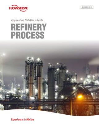
  • 1. 1 Application Solutions Guide — The Global Combined Cycle Landscape REFINERY PROCESS Application Solutions Guide Experience In Motion DECEMBER 2019
  • 2. 2 Application Solutions Guide — Refinery Process TABLE OF CONTENTS GLOBAL REFINERY LANDSCAPE . . . . . . . . . . . . 6 Market Overview. . . . . . . . . . . . . . . . . . . . . . . . . 6 Nelson Refinery Complexity. . . . . . . . . . . . . 8 The Equivalent Distillation Capacity. . . . . . . 8 Refinery Crude Terminology. . . . . . . . . . . . . 8 American Petroleum Institute Terminology. . 9 Examples of Industry Standards . . . . . . . . . 9 Refinery Process Overview . . . . . . . . . . . . 11 A CLOSER LOOK AT REFINERY PROCESSES . . . . . . . . . . . . . . . . . . . . 15 Cut Points. . . . . . . . . . . . . . . . . . . . . . . . . . . . . 15 FCC . . . . . . . . . . . . . . . . . . . . . . . . . . . . . . 15 Hydrocracker. . . . . . . . . . . . . . . . . . . . . . . 16 Ebullated Bed Hydrocracker . . . . . . . . . . . 16 Naphtha Fractions . . . . . . . . . . . . . . . . . . . 16 LPG and Gas Fractions . . . . . . . . . . . . . . . 17 Hydrotreating. . . . . . . . . . . . . . . . . . . . . . . 17 Refinery Conversion. . . . . . . . . . . . . . . . . . . . . 18 Conversion Processes. . . . . . . . . . . . . . . . 19 Hydrogen Plant. . . . . . . . . . . . . . . . . . . . . . . . . 20 Desalter . . . . . . . . . . . . . . . . . . . . . . . . . . . . . . 20 Nitrogen Plant. . . . . . . . . . . . . . . . . . . . . . . . . . 20 Amine Treating . . . . . . . . . . . . . . . . . . . . . . . . . 20 Sulphur Recovery. . . . . . . . . . . . . . . . . . . . . . . 20 Asphalt Plant. . . . . . . . . . . . . . . . . . . . . . . . . . . 20 Feed Stock and Gases, Key Processes and Finished Product PFD. . . . . . . . . . . . . . . . 21 Critical Pump and Valve Products by Process. . . . . . . . . . . . . . . . . . . . . 22 Flowserve Pumps. . . . . . . . . . . . . . . . . . . . 22 Slurry Oil Pump . . . . . . . . . . . . . . . . . . . . . . 23 Feed Charge Pump . . . . . . . . . . . . . . . . . . 23 Reactor and Recycle Pumps. . . . . . . . . . . 24 Decoking Pumps. . . . . . . . . . . . . . . . . . . . 24 Coker Heater Charge. . . . . . . . . . . . . . . . . 24 Jet Pump . . . . . . . . . . . . . . . . . . . . . . . . . . 25 Bottom Unheading Flowserve Valve . . . . . . 25 Decoking Control Valve . . . . . . . . . . . . . . . 25 Alkylation Pumps. . . . . . . . . . . . . . . . . . . . 26 Hydrotreater Pumps. . . . . . . . . . . . . . . . . . 26 Amine Pumps. . . . . . . . . . . . . . . . . . . . . . . 26 Specialized Vacuum Pumps. . . . . . . . . . . . 27
  • 3. 3 Application Solutions Guide — Refinery Process TABLE OF CONTENTS (CONTINUED) KEY REFINERY PROCESSES WITH EQUIPMENT . . . . . . . . . . . . . . . . . . . . . . . . . 28 Atmospheric Distillation Detailed Process . . . . 28 Sample of Atmospheric Distillation Application Conditions . . . . . . . 32 Vacuum Distillation Detailed Process. . . . . . . . 34 Recommended Control Valve Features for Vacuum Distillation. . . . . . . . . 37 Delayed Coking Detailed Process . . . . . . . . . . 38 Delayed Coker Unit Overview . . . . . . . . . . 38 Application Guides. . . . . . . . . . . . . . . . . . . 40 DCU System Overview. . . . . . . . . . . . . . . . 41 Pioneers in Decoking Pumps. . . . . . . . . . . 44 Hydrotreater Detailed Process. . . . . . . . . . . . . 46 Hydrotreater Process Description . . . . . . . . 51 Critical Pumps . . . . . . . . . . . . . . . . . . . . . . 52 Fluid Catalytic Cracking Detailed Process . . 53 FCC Process Description. . . . . . . . . . . . . . 57 FCC Centrifugal Pumps. . . . . . . . . . . . . . . 58 Fluid Catalytic Cracking Power Recovery. . . . . . . . . . . . . . . . . . . . . 58 Critical FCC Pumps and Valves. . . . . . . . . 60 Hydrocracker Detailed Process . . . . . . . . . . . . 63 Process Description. . . . . . . . . . . . . . . . . . 67 Critical Pumps . . . . . . . . . . . . . . . . . . . . . . 69 Special Note. . . . . . . . . . . . . . . . . . . . . . . . 72 Catalytic Reformer . . . . . . . . . . . . . . . . . . . . . . 73 Why Is This Process So Important to Flowserve?. . . . . . . . . . . . . . . 74 Process Description. . . . . . . . . . . . . . . . . . 75 Catalytic Reformer Unit . . . . . . . . . . . . . . . . 76 Isomerization . . . . . . . . . . . . . . . . . . . . . . . . . . . 80 Isomerization in the Refinery Process . . . . 80 Alkylation (Hydrofluoric) . . . . . . . . . . . . . . . . . . 82 Alkylation Application. . . . . . . . . . . . . . . . . 83 Vapor Recovery Unit. . . . . . . . . . . . . . . . . . . . . 85 Vacuum or Flue and Flare Gas Applications. . . . . . . . . . . . . . . . 86 Auxiliary (Power House). . . . . . . . . . . . . . . . . . 89 Steam and Power. . . . . . . . . . . . . . . . . . . . 89 Tank Farms, Blending (Mixing) and Off-Sites. . 89 Tankage and Blending. . . . . . . . . . . . . . . . 89 Off-Sites and Wastewater. . . . . . . . . . . . . . 89 Hydrodesulphurization . . . . . . . . . . . . . . . . . . . . . . . 92 Amine Treating Unit . . . . . . . . . . . . . . . . . . . . . . 93 Sulfur Recovery Unit. . . . . . . . . . . . . . . . . . . . . 95 Centrifugal Pumps. . . . . . . . . . . . . . . . . . . 95 Application Review. . . . . . . . . . . . . . . . . . . 95 Asphalt Plant. . . . . . . . . . . . . . . . . . . . . . . . . . . 96
  • 4. 4 Application Solutions Guide — Refinery Process TABLE OF CONTENTS (CONTINUED) GLOBAL REFINERY LANDSCAPE . . . . . . . . . . . 97 Business Impact and Focus Areas. . . . . . . . . . 97 Products for Refinery — At a Glance. . . . . . . . 99 Industry-Leading Brands. . . . . . . . . . . . . . 99 Pump Types. . . . . . . . . . . . . . . . . . . . . . . 100 Block Valve Types . . . . . . . . . . . . . . . . . . . 119 Ball Valves . . . . . . . . . . . . . . . . . . . . . . . . 119 Plug Valves. . . . . . . . . . . . . . . . . . . . . . . . 119 Butterfly Valves. . . . . . . . . . . . . . . . . . . . . 119 Actuators . . . . . . . . . . . . . . . . . . . . . . . . . 126 Control Valves Types . . . . . . . . . . . . . . . . 135 Typical Flowserve Control Valves. . . . . . . 136 Seals and System Types . . . . . . . . . . . . . 139 Seal System Piping Plans. . . . . . . . . . . . . 144 AFTERMARKET PARTS AND SERVICES IN REFINERIES . . . . . . . . . . . . . . . . . 146 Mechanical Upgrades and Retrofits. . . . . . . . 146 LifeCycle Management Programs . . . . . . . . . . 147 Educational and Consultative Services . . . . . . 147 Replacement Parts and Component Offerings. . . . . . . . . . . . . . . . . . . 148 Standard OEM Replacement Parts and Components . . . . . . . . . . . . . . . 148 Parts Programs. . . . . . . . . . . . . . . . . . . . . 148 Quick Response Programs . . . . . . . . . . . . 148 Rapid Prototyping. . . . . . . . . . . . . . . . . . . 149 Equipment Performance. . . . . . . . . . . . . . 149 Strategic Procurement. . . . . . . . . . . . . . . 149 Streamlined Inventory. . . . . . . . . . . . . . . . 150 Technical Support . . . . . . . . . . . . . . . . . . 150 Tools and Technology . . . . . . . . . . . . . . . . 150 Large Capital Project Support. . . . . . . . . . . . 152 Quick-Ship Products. . . . . . . . . . . . . . . . . . . . 152 Upgrade Programs. . . . . . . . . . . . . . . . . . . . . 153 RVX Upgrade. . . . . . . . . . . . . . . . . . . . . . 153 INSTALLATIONS AND EXPERIENCE . . . . . . . . 156 Preferred Supplier Agreements . . . . . . . . . . . . 156 Trusted Experience Across the Oil and Gas Industry. . . . . . . . . . . . . 157 Global Accounts. . . . . . . . . . . . . . . . . . . . 157
  • 5. 5 Application Solutions Guide — Refinery Process TABLE OF CONTENTS (CONTINUED) COMMUNICATING OUR VALUE. . . . . . . . . . . . . 158 Flowserve Value Proposition for Refineries. . . . . . . . . . . . . . . . . . . . . . . . . . 158 Innovative Ways Flowserve Addresses Customer Challenges. . . . . . . . . . 159 Business Pain Points and Opportunities. . . . . 160 Flowserve Meets the Customers’ Challenges . . . . . . . . . . . . . . 160 Business Pains and Challenges. . . . . . . . 160 Typical User Challenges With Valves in the Processes. . . . . . . . . . 163 Hydrocracking Process Challenges on Pumps and Valves. . . . . . 164 Solutions for Challenges in Hydrocracker Installations . . . . . . . . . . . . 165 Value Proposition Summary: Why Flowserve? . . . . . . . . . . . . . . . . . . . . . . . 167 Industry-Leading Products and Services in Refinery Processes. . . . . . . . 167
  • 6. 6 Application Solutions Guide — Refinery Process GLOBAL REFINERY LANDSCAPE GLOBAL REFINERY LANDSCAPE Market Overview Modern refineries are complex facilities, processing products into a number of various specifications. Refineries are designed or enhanced to make a wide variety of products: gasoline, fuel oil, lube oils, jet/condensates, solvents, diesels, asphalts, coke and gases/LPGs. An average refinery size is between 100 000 to 400 000 BPD. For the purposes of this guide, all our estimates and references are for 200 000 BPD refineries. The composition of crude oils varies significantly, depending upon their source. Refineries are complex systems with multiple operations. • The basics of all refineries are the same, but the specific operations vary and depend on: –Properties of the crude oil refined –Desired finished product output Table 1.1: Refining process CRUDE OIL ▼ REFINERY Light Fuels Natural Gas (Methane) Ethane/Propane Liquefied Propane & Butane ▼ Chemicals Benzene Ethylbenzene Xylene ▼ Liquid Fuels Gasoline Diesel Kerosene Jet Fuel & Naphtha ▼ Lubes Lube Oils Grease ▼ Residuals Residual Fuel Asphalt ▼ Ethylene Plants Propylene Plants Chemical Plants ▼ Chemical Plants ▼ Consumer Uses Chemical Plants Ethylene Plants Propylene ▼ Consumer and Industrial Users ▼ Industrial Users Roads, etc. ▼ Polyethylene Polypropylene Nylon Styrene Polyester Gasoline Jet Fuels Diesel Heating Oil Motor Oil Grease Heating Oil Bunker C Asphalt Roofing Material
  • 7. 7 Application Solutions Guide — Refinery Process GLOBAL REFINERY LANDSCAPE refineries are geared toward specific products or are smaller in size. In this regard, refinery operations are predicated on the performance of the mechanical equipment, e.g., pumps, valves, blowers, compressors, drivers and seal systems. The application of these products is key to be properly sized and designed for satisfactory MTBF. Equipment such as pumps and valves usually represent 10% to 15% of the capital investment in the refinery processes; they are the most important type of equipment with respect to plant reliability. Twenty-first-century technologies have improved to make the processes more efficient, steam and cracking less risky, and MTBF longer for maintenance/shutdown schedules. Shale gas has become an alternative to naphtha as the feed stock to petrochemical sites due to low cost feed stock (specifically in North America) but more important, the electronic monitoring and controls for safety, process improvements and life cycle costs. Today’s CONVERSION SEPARATION STORAGE AND BLENDING Crude Gasoline Gas Naphtha Kerosene Fuel Oil Residual/Asphalt Separation Crude Oil into Various Fractions Based on Boiling Point • Crude Desalter • Atmosphere Crude Unit • Vacuum Crude Unit Converts Lower Value Products into High-Demand, Premium Products • Residual Conversion • Middle Distillate Upgrading • Light Ends Processing Combines the Various Components from the Conversion Processes into End-Use Products BLENDING Figure 1.1: Basic refinery process flow
  • 8. 8 Application Solutions Guide — Refinery Process Nelson Refinery Complexity (NCI) Allows comparison between different types of refineries. • Simple “hydroskimming” refineries may only separate and treat • Complex “hydrocracking” refineries will also have several conversion processes The Nelson complexity index (NCI) is a measure to compare the secondary conversion capacity of a petroleum refinery with the primary distillation capacity. The index provides an easy metric for quantifying and ranking the complexity of various refineries and units. To calculate the index, it is necessary to use complexity factors, which compare the cost of upgrading units to the cost of crude distillation unit. The Equivalent Distillation Capacity (EDC) • Each unit is assigned a complexity index based on cost relative to the atmospheric crude unit • The sum of the unit complexities normalized to the atmospheric distillation capacity Refinery Crude Terminology API (American Petroleum Institute) gravity crude oil is classified as light, medium or heavy, according to its measured API gravity. • Light crude oil is defined as having an API gravity higher than 31.1° API • Medium oil is defined as having an API gravity between 22.3° API and 31.1° API • Heavy oil is defined as having an API gravity below 22.3° API 1 barrel equals 42 U.S. gallons 1 BPD = Gallons / (hrs*min) = 42 / (24*60) = .0292 gpm 1 gpm = 34.29 BPD 1 barrel equals 158.984 liters The approximate conversion for BPD to tonnes/year is 49.8, so 100 000 BPD equals around 4 980 000 tonnes per year. Crude oil has virtually no value in its raw form. Value is added by refining it into sellable fuels and chemical (Naphtha & Ethane) feed stocks. GLOBAL REFINERY LANDSCAPE Table 1.3: Circa 2014 Table 1.2: Generalized complexity indices Refining Process Generalized complexity index Atmospheric distillation 1 Vacuum distillation 2 Delayed coking 6 Visbreaking 2 .75 Catalytic cracking 6 Catalytic reforming 5 Catalytic hydrocracking 6 Catalytic hydrorefining 3 Refining Process Generalized complexity index Catalytic hydrotreating 2 Alkylation/polymerization 10 Aromatics/isomerization 15 Lubes 10 Asphalt 1.5 Hydrogen (MCFD) 1 Oxygenates MTBE 10 Holland US China Russia # Refineries 6 125 54 40 Crude M B/D 1197 17 788 6866 5431 Complexity 7.85 9.62 2.26 4.56 EDC ME B/D 9336 171 190 15 551 24 785
  • 9. 9 Application Solutions Guide — Refinery Process Category 1 (ASME B73.1) Type A (Pusher) Type B (Bellows) Type C (High Temp Bellows) Arrangement 1 (Single) Arrangement 2 (Unpressurized Dual) Arrangement 3 (Pressurized Dual) Category 1 (API 610) • Pump Type • Seal Type • Arrangement Examples of Industry Standards GLOBAL REFINERY LANDSCAPE Figure 1.3: API 682 for seals Figure 1.2: API 610 for pumps American Petroleum Institute (API) Terminology The oil and gas industry uses a series of specifications for pumps, seals, systems and valves. These specifications and guides provide standards used globally, which all manufacturers are directly involved, and have committees established to define everything from scope of product types to vibrations, materials and test standards.
  • 10. 10 Application Solutions Guide — Refinery Process GLOBAL REFINERY LANDSCAPE Figure 1.4: In-process refinery end products and finished marketable refinery end products diagram API for valves The oil and gas industry does not use a universal API specification for valves like they have on pumps and seal systems; however, there are a few specs written, to which are often referred. 1-ANSI: 1610/1634, which are more dimensional guides 2-NACE: specs for metallurgy
  • 11. 11 Application Solutions Guide — Refinery Process GLOBAL REFINERY LANDSCAPE Refinery Process Overview The feedstock of crude oil is a gooey mixture of various hydrocarbons which is de-salted, heated, separated and broken down big molecules of un-useable heavy product into smaller molecules of useable lighter products. The heavier products are fed into catalytic cracking or hydrocracking units to obtain gasoline, naphtha and middle distillates. Catalysts are used to improve the yield of the gasoline and lighter products in the cracker. A catalyst is a substance which facilitates a chemical reaction without being consumed in the reaction. Hydrocracking is similar, but done in an atmosphere of hydrogen (second key feed stock to a refinery). The hydrogenation increases the yield of gasoline and produces saturated hydrocarbons which do not gum up with time. Hydrogen sites are not always directly located at a refinery, but are key feedstock to several processes within the refinery. Hydrotreating or reforming improves the quality of finished products and can require several treaters in a refinery based on the various products broken down after distillation. Hydrotreating stabilizes as saturated non- gumming molecules and with reforming, re-arranges the structure to improve to high-octane aromatics. Naphtha is processed and used in gasoline and solvents, and continues to be key today as the feedstock for petrochemical or polyethylene crackers in chemical plants. However, in the past decade, shale gas which is a primary product of ethane is also a key, and growing feedstock to the petrochemical industry. The wet gas from the fractionated units in the vapor recovery splits into fuel gas, LPG, butane, isobutane and unsaturated hydrocarbons. Fuel gas is used in refinery heaters. Butane gets blended into LPG or gasoline, and the unsaturated hydrocarbons along with isobutene are sent to the alkylation unit for conversion into high-octane compounds to be blended into jet fuel and premium gasoline. An alky unit uses sulfuric or hydrofluoric acid as the catalyst to react to unsaturated hydrocarbons with isobutene to form high-octane isoparaffins compounds. Off-Sites Superintendent Area 1 • Crude • Vacuum • Coke • Visbreaker Area 2 •Alkylation • FCCU •Gas Plant •Hydrocracker Area 3 •Reformer •Utilities •Hydrotreater •SRU Blending Movement Dock & Terminals Purchasing/Supply Process Engineering Project Engineering I & E Process Mechanical Drafting Off-Sites Superintendent Technical Services Design Maintenance Safety Planning/ Scheduling Vice President—Refining Refinery Manager Operations Manager Engineering Manager Figure 1.5: Refinery management and process owner’s organization example Customers expect the equipment suppliers they prefer to have a vast understanding of the refinery operations, i.e., what is expected of the processes in which the equipment is applied and the overall process scheme. More important is the support on tough services.
  • 12. GLOBAL REFINERY LANDSCAPE Figure 1.6: Refining process diagram Figure 1.6 below illustrates the various complex refinery processes, starting with the feedstock of crude oil and production of marketable products. Additionally, it also shows where the primary pumps and control valves are placed. 12 Application Solutions Guide — Refinery Process
  • 13. 13 Application Solutions Guide — Refinery Process GLOBAL REFINERY LANDSCAPE Heavy Crude Light Crude Cumulative Percent Volume 0 3 10 100 20 30 40 50 60 70 80 85 97 Boiling Temperature (°C) Boiling Temperature (°F) 1200 1000 800 600 400 200 0 625 525 410 300 190 80 0 Residue Gas Oil Diesel Kerosene Naphtha Gasoline Butanes & Light Ends Figure 1.7: The chart below shows the break point for fractions in a refinery The maze of equipment in Figure 1.6 is subdivided into individual process units, each with its own function to perform. The sizes and types of process are dependent on the type of crude charged to the unit and the type of products produced for the specific targeted market. Each box in Figure 1.6 represents a process unit—atmospheric distillation, hydrotreater, hydrocracking, reformer, alkylation, isomerization, decoking, FCC, etc., which all get mixed together to form the final marketable product. Additionally, the breaking points in a refinery (boiling temperatures) are defined in figure 1.7.
  • 14. 14 Application Solutions Guide — Refinery Process GLOBAL REFINERY LANDSCAPE Most important, all these processes use Flowserve products in vast applications and dependable service life. Flowserve and its legacy product brands of valves, pumps and seal systems are pioneers in many applications and processes such as hydraulic decoking systems. Also, not shown on the flow diagram are the blending (mixing) tank farms and utility equipment, better known as the powerhouse. Flowserve products also are used in these many applications on which customers depend; we strive to continuously meet their expectations. Figure 1.8: The following chart shares the thermal variance in the primary tower
  • 15. 15 Application Solutions Guide — Refinery Process A CLOSER LOOK AT REFINERY PROCESSES A CLOSER LOOK AT REFINERY PROCESSES To support the process flow, next we will share the processes used in a refinery to follow the crude fractions in each process and highlight how Flowserve products fit in. Cut Points Initial boiling point (IBP): temperature at which a product (or cut or fraction) begins to boil. End point: the temperature at which product is 100% vaporized. The first major process in all refineries is atmospheric distillation. Here the crude is heated to its boiling point and separated by means of fractionating columns into various fractions from heavy to light. Each of the downstream processing units will require feedstocks that start with the properties to meet the marketable product requirements. Most refineries accomplish the distillation process in two steps. First, by fractionating the total crude supply at atmospheric pressure noted above. Second, by feeding the heaviest fraction, atmospheric “bottoms” from the atmospheric distillation unit to a second fractionator operating at a high vacuum called vacuum distillation. These heavy fractions are boiled under a vacuum to make a product suitable for the manufacture of coke in the delayed coker, which are also used for heavy fuel oils. The gas oil fractions from the crude unit are feedstocks for gasoline and diesel fuel. These oils are pumped to the Fluid Catalytic Cracking Unit (FCC) and the hydrocracking units for producing various forms of gasoline, light fuel oils and diesel fuels. The fractionating units separate these products after the cracking reaction takes place so they can be segregated for final treatment prior to market transfer. FCC: A Catalytic Cracking Process That Does Not Add Hydrogen • Heavy and light gas oils feed from the crude and other units are pumped through a heater and mixed with a catalyst • Catalyst promotes the cracking process − The catalyst has a very high surface area, which accelerates the reaction. The catalyst does not change chemically. • The cracked products are sent to a fractionator for separation • The target product is gasoline • Total product volume is increased − Product mass decreases Table 2.1 Fraction Cut Points, °C Cut Points, °F IBP End IBP End Butane & Lighter < 30 < 90 Gasoline 30 100 90 220 Naphtha 100 160 220 315 Kerosene 160 230 315 450 Light Gas Oil 230 340 450 650 Heavy Gas Oil 340 540 650 800 Resid >540 >800
  • 16. 16 Application Solutions Guide — Refinery Process Hydrocracker: A Catalytic Cracking Process in the Presence of Hydrogen • Feeds heavy gas oil from the crude units, FCC and/or delayed coker • It takes in the worst of the distillate stocks and outturns a better-than-average gasoline blending component • Relatively large amount of isobutane is produced − Useful in balancing feed to the alky plant • Also reduces impurities like sulfur, metals and nitrogen The hydrocracker is a pivot point in the refinery: • It can swing refinery yields among gasoline, distillate fuel and jet fuel, and simultaneously improve product quality • Operation depends on: − Feed rates − Operating conditions of other resid units (FCC and/or coker) that feed the hydrocracker • In addition, the hydrocracker: − Feeds the alky plant with isobutane − Feeds the cat reformer with naphtha Ebullated Bed Hydrocracker A catalytic, hydrogenation cracking process where the catalyst bed is kept in constant motion (ebullated) within the reactor. • Combines thermal, catalytic cracking and hydrogenation • Treats resid with hydrogen in presence of an ebullated catalyst bed to produce low sulfur, residuum and distillates, or both • Two process licensors and fewer than 20 units in the world • High operating conditions; typically, up to 454ºC (850ºF) and 238 bar (3452 psi) Naphtha Fractions The light naphtha components from distillers are sent to the catalytic reformer for making gasoline with higher octane levels. This product is mixed with gasoline from the catalytic cracking unit and the hydrocracker to obtain the desired octane numbers of the various grades of gasolines. The alkylation unit also produces a high-octane component for blending into gasoline. A CLOSER LOOK AT REFINERY PROCESSES
  • 17. 17 Application Solutions Guide — Refinery Process LPG and Gas Fractions The lightest fractions from the distillation unit are used for LPG or bottled gases. They are mixed with the lighter components from the refinery processes to produce the marketable final products. Refineries have a group of processes at various stages of the process flow diagram called hydrotreaters, whose primary role is to remove sulfur from the product streams prior to them be processed further. Removing sulfur from the final product is necessary, but also benefits from the standpoint of corrosion and process efficiency prior to the high-temperature process reactions. Hydrotreating • The light streams from the crude unit to the alky and isomeric units • Gas oil streams before they enter the FCC • Raw diesel oil streams from the crude unit • Naphtha streams from the FCC before mixing in the gasoline pool A CLOSER LOOK AT REFINERY PROCESSES
  • 18. 18 Application Solutions Guide — Refinery Process Refinery Conversion Most money, time and effort are spent on the conversion because this is where the money is made in a refinery. • All conversion processes change the fraction at the molecular level. • Using heat, catalyst and sometimes pressure, large hydrocarbon molecules are decomposed or “cracked” into lighter, smaller molecules. • Conversion of low-value fractions (resid) to high-value products (gasoline and diesel) Table 2.2 PROCESS UNITS BY CATEGORY Processing Category Type Unit Type Separation ATM Crude Distillation VAC Distillation Reducing Average Molecular Weight Delayed Coking GO/VR Hydrocracking Visbreaking Quality Improvement Hydrotreating (All Streams) Catalytic Reforming Isomerization Increasing Average Molecular Weight Alkylation A CLOSER LOOK AT REFINERY PROCESSES
  • 19. 19 Application Solutions Guide — Refinery Process A CLOSER LOOK AT REFINERY PROCESSES One of the other feedstocks to a refinery is hydrogen, used in most of the processes (hydrotreater, isomerization, FCC and reformer) and is a complex capital intensive unit. Figure 2.1: Conversion process—typical refinery Conversion Processes • Catalytic cracking • Hydrocracking • Delayed coking • Visbreaking • Catalytic reforming • Alkylation • Isomerization In summary (Figure 2.1), simplified feedstock and commercial end products:
  • 20. 20 Application Solutions Guide — Refinery Process A CLOSER LOOK AT REFINERY PROCESSES Hydrogen Plant Refineries are large users of hydrogen. In a typical refinery, the processes described below use hydrogen. The hydrogen is manufactured on-site using a steam reforming process. Propane feed is mixed with super-heated steam and reformed in the presence of catalysts at 1400 to 1600°F. The resultant gas (CO2 /H2 ) is passed through an amine scrubber to remove the CO2 . The pump metallurgies for this area are all chrome steel, reflecting the corrosive nature of the CO2 mixtures and the boiler feed water. The pumps on this unit are at 100% capacity and normally no standby. Desalter Crude oil often contains water, inorganic salts, suspended solids and water-soluble trace metals. These contaminants must be removed to reduce corrosion, plugging and fouling of equipment, and prevent poisoning catalysts in downstream processing units. Desalting, the first step and one of the most critical processes in refining, removes these contaminants. Desalter efficiency can have a dramatic impact on nearly every downstream unit. Crude oil desalting is the process of “washing” the crude with water to extract salts and solids. The two most typical methods of crude-oil desalting, chemical and electrostatic separation, use hot water as the extraction agent. In chemical desalting, water and chemical surfactants (demulsifiers) are added to the crude, heated so that salts and other impurities dissolve into or attach to the water, and then are held in a tank where they settle out. Electrical desalting is the application of high-voltage electrostatic charges to concentrate suspended water globules in the bottom of the settling tank. Surfactants are added only when the crude has a large amount of suspended solids. Both methods of desalting are continuous. Nitrogen Plant In remote geographic locations, nitrogen for process use may be manufactured on-site. In heavily industrialized areas, nitrogen as well as hydrogen, would be purchased outside. A typical nitrogen plant for a refinery this size would contain four centrifugal pumps operating at ambient temperatures, with flows to 75 gpm and heads to 380 feet. Caustic is used in the process. Some 316SS is used in pump construction. The pumps are at 100% capacity without standby. Sufficient nitrogen can be stored to satisfy requirements during unit maintenance. Amine Treating This process is used for dehydrating and acid gas removal from refinery gases. An amine solution is contacted with the sour gases absorbing the impurities. The amine solution is then regenerated. H2 S saturated water is also removed from the stream. Pumping temperatures range from 100 to 250°F and pressures to 500 psig. 316SS and Alloy 20 are used on the more corrosive sour water services. Flowserve SIHI® vacuum units are good applications. Sulfur Recovery Sulfur removal is an integral part of today’s refineries, both from the low sulfur fuel point of view and the pretreatment required for processes using a catalyst. The recovery and sale of sulfur are important parts of the refinery. Centrifugal OH2 API pumps are used in this area for handling molten sulfur and sour water. Both of these services require 316SS. Asphalt Plant This area uses positive displacement pumps for handling the high-viscosity product at 300 to 500°F Flowserve does not have this product in the portfolio.
  • 21. 21 Application Solutions Guide — Refinery Process A CLOSER LOOK AT REFINERY PROCESSES Feed Stock and Gases, Key Processes and Finished Product PFD Figure 2.2: Refinery flow chart
  • 22. 22 Application Solutions Guide — Refinery Process A CLOSER LOOK AT REFINERY PROCESSES Critical Pump Products by Process In summary, it is important to recognize each refinery globally has its own unique processing scheme which is determined by the equipment available, operating costs and the marketable products demand. The optimum flow pattern for any refinery is dictated by economic considerations, and no two refineries are identical in their operational platform. Flowserve Pumps PROCESSING UNIT API PUMP CODE QUANTITY OF PUMPS Atmospheric Tower OH2 BB2 25 6 Delayed Coker OH2 BB2 BB5 42 2 3 FCC (Fluidized Bed Catalytic Cracking OH2 BB2 22 8 H.F. (Hydrofluoric) Alkylation OH2 BB2 10 4 Naphtha Reforming OH2 BB5 4 2 Hydrotreater OH2 BB5 4 2 Hydrocracker BB5 8 Hydro-Desulfurization OH2 BB2 BB5 2 2 3 Total OH2 BB2 BB5 114 22 14 Table 2.3: Processing unit in a typical 100 000 barrels/day refinery Additional non-API products can include other Flowserve products with Split Case, Verticals and ASME ISO as defined in the next pages.
  • 23. 23 Application Solutions Guide — Refinery Process A CLOSER LOOK AT REFINERY PROCESSES Slurry Oil Pump • Catalyst fines cause severe erosion • High catalyst content requires either coatings or the Lawrence® legacy product HPX6000 pump to prevent erosion as shown here Feed Charge Pump • The high pressure generally requires a barrel pump − Usually unspared (IDP® ) HDO model − Some refiners use a (IDP) DMX model • An HPRT may be used downstream of the reactors to recover energy from the high-pressure stream Pump: 10x12x15 DMX –10-stage • Capacity: 616 m3 /hr (2710 gpm) • TDH: 1990 m (6530 feet) HPRT: 6x8x13L HDO six-stage • Cap: 393 m3 /hr (1730 gpm) • TDH: 1515 m (4970 feet)
  • 24. 24 Application Solutions Guide — Refinery Process A CLOSER LOOK AT REFINERY PROCESSES Decoking Pumps Decoking (DCU) has several Flowserve products, but four critical applications: 1. Coker Heater Charge Several options—model HED, DSTHF, barrel pump with coke cutter Flowserve type PR reactor recycle pumps (ebullators) are essential high-temperature, high-press (BJ) canned motor pumps. Figure 2.3: Ebullated bed hydrocracking Reactor and Recycle Pumps
  • 25. 25 Application Solutions Guide — Refinery Process A CLOSER LOOK AT REFINERY PROCESSES 2. Jet Pump The largest pump in the refinery • Pressures to 305 bar (5000 psi) • Power to 3700 kW (5000 hp) • Model WIK pump is the current standard − Other heritage barrels have been used • Unspared duty with abrasive coke fines (EMA might use slower-running product “Worthington legacy” WC pump.) 3. Bottom Unheading Flowserve Valve 4. Decoking Control Valve Two-way valve to control flow from the jet pump • Function is changed by moving the valve stem • The Flowserve new advanced DCV ADCV simplifies maintenance by allowing field replacement of the orifice stack. − Direct replacement of the Flowserve DCV with no piping modifications
  • 26. 26 Application Solutions Guide — Refinery Process A CLOSER LOOK AT REFINERY PROCESSES Alkylation Pumps The challenge of alkylation is not pressure or temperature, but the hazardous acids. • HF is an especially nasty fluid • Standard OH2 or OH3 pumps can be used − Special decontamination is needed when working an alky pumps − Seals are of prime importance − Sealless (mag drive) pumps have been explored Hydrotreater Pumps • Temperatures of 300 to 400ºC (570 to 750ºF) • Pressures vary from 30 to130 bar (430 to 1900 psi) • Typical API process pumps are used • Model DMX may be used as charge pump Amine Pumps Pump Types • Amine is corrosive and hazardous; C6 NACE or A8 material; dual seals • Model DMX common for lean amine pump • OH2/OH3 model HPX process pumps for reflux • Watch for NPSHA and gas breakout in design considerations HPX PHL DMX DMX
  • 27. 27 Application Solutions Guide — Refinery Process Typical vacuum pump package A CLOSER LOOK AT REFINERY PROCESSES Specialized Vacuum Pumps (SIHI Compressor or Liquid Ring Products) Figure 2.4: Refinery simplified
  • 28. 28 Application Solutions Guide — Refinery Process KEY REFINERY PROCESSES WITH EQUIPMENT Atmospheric Distillation Detailed Process Atmospheric distillation or topping unit is the starting point in a refinery. As you will recall, it uses HPX OH2 and HDX BB2 pumps. The basic objective here is to separate the crude oil into its main fractions. This separation is done in a tall tower, which operates on the same principle as a moonshiner’s still, i.e., distillation. The temperature in the tower decreases as you move from bottom to top. Consequently, various fractions condense at different levels in the tower at points where the temperature falls below their boiling point. The lighter fractions condense toward the top of the tower where temperatures are lower and the heaviest fraction remains at the bottom where the temperature is the highest. The following is a simple schematic of an atmospheric crude distillation unit: Crude oil is pumped by a charge pump through heat exchangers to a desalter. The desalter removes salt from the crude. If the salt is not removed, then it would deposit in heaters and also cause corrosion due to the acid formed by the decomposition of the chloride salt. KEY REFINERY PROCESSES WITH EQUIPMENT Figure 3.1: Schematic of an atmospheric crude distillation unit
  • 29. 29 Application Solutions Guide — Refinery Process KEY REFINERY PROCESSES WITH EQUIPMENT Desalter unit: After desalting, the crude oil is pumped through a series of heat exchangers to raise its temperature to 550°F by heat exchange with product and reflux streams. These heat exchangers conserve energy by recovering heat from the product and reflux streams. Refineries are sensitive to conserving energy, either in process heat or pump and compressor operating efficiencies. Aftermarket opportunities improve energy conservation and are helpful in selling the energy-saving benefits of Flowserve technology and enhancements. Returning to the flow chart (Figure 3.1), the crude is further heated to 750°F in a heater and charged into the atmospheric tower where it flashes; i.e., a large portion of the liquid crude turns into vapor due to the pressure drop. The vapors on their way upward bubble through the cooler liquid laying on the bubble-cap tray. During the bubbling, the heavier fraction condenses on the tray and the lighter fraction rises to the next tray. A portion of the vapor condenses at every tray. Reflux — or the cooling medium necessary to maintain lower temperatures in the higher zones — is provided by condensing the tower overhead vapors and pumping a portion of the condensed liquid to the top of the tower. Cooling is also provided by pumping around what is cooling and pumping the liquid from a higher and cooler zone to a lower and hotter part of the tower. Also, note that internal reflux is provided by the cooler liquid from a higher tray overflowing through the spout to the tray below.
  • 30. 30 Application Solutions Guide — Refinery Process KEY REFINERY PROCESSES WITH EQUIPMENT The liquid side streams withdrawn from the tower will contain low boiling components. They are hazardous, as they increase the tendency of the product to flash at lower temperatures. These light ends are stripped from each side stream in a separate small stripping tower by heating the liquid with steam. Each side stream is then pumped through a heat exchanger to downstream treating and blending units. Usually at least four side strippers are used in a plant to produce extra cuts such as kerosene and diesel. The heavier fractions in the vapors from the top of the tower are condensed in a condenser. This is the light gasoline portion of the vapors. Some of condensate is returned to the top of the tower as reflux and the remainder is sent to the LSR (low straight run gasoline stabilization unit). The uncondensed vapor is compressed in a reciprocating compressor and sent to the LPG recovery unit. The major Flowserve interest in crude distillation units is the valves and pumping equipment. Usually there are more process control valves and pumps in a crude unit than any other process unit in a refinery. Of course, the sizes of the pumps are dependent on the quantity of crude entering the plant. Figure 3.2: Simplified diagram—crude distillation
  • 31. 31 Application Solutions Guide — Refinery Process KEY REFINERY PROCESSES WITH EQUIPMENT From the process description, following is a partial list of the critical pumps on a typical crude unit.The pumping service can be associated with the process description. 1. Crude Charge Pump Usually takes suction off the discharge of the crude tank booster pump. Operates at atmospheric temperatures and fairly high pressure to overcome the system pressure drop due to exchangers, desalter and the furnace. An HPX pump will usually handle this service, but for the larger plants, the HDX may be better suited. 2. Reflux and Tops Pump Usually a combined service. The pump takes suction on an accumulator at the top of the column and pumps part of the stream back into the column and part to gasoline storage. Type HPX pump with low NPSH requirements is the pump for the job. It operates at approximately 150 to 200°F. 3. Intermediate Reflux Pump Takes suction on an intermediate tray and pumps through an exchanger back into the column. Pumping temperature is about 300 to 400°F and is an ideal service for the type HPX pump. 4. Gas Oil Pump Takes suction on the bottom of the side cut stripper, HPX, HDX or HED low NPSH requirement, 500 to 600°F pumping temperature. 5. Naphtha, Kerosene and Diesel HPX Pumps Similar to above gas oil pump, but lower pumping temperature. 6. Topped Crude Pump Takes suction from bottom of fractionator and pumps liquid to vacuum tower for further fractionation. Pump operates at 700°F low NPSH and it is either an HED, HDX or possibly HPX. Because of the sulfur in most crude oils, when pump temperature exceeds 550°F, it is necessary to consider the use of alloys, such as 11% to 13% chrome for pump case, impeller and wearing parts. Flowserve mechanical seals have been developed for all of the above pumping services and should be applied with minimum problems. Please refer to Refinery Mechanical Seal section of the guide.
  • 32. 32 Application Solutions Guide — Refinery Process KEY REFINERY PROCESSES WITH EQUIPMENT Sample of atmospheric distillation pump application for typical smaller BPD refinery, most of which are HPX products. Crude charge, three required, 4850 gpm each Design: 600 psig @ 100°F 1050 ft head Complete with drivers (two motors, one turbine) Furnace charge, three required, 5325 gpm each Design: 600 psig @ 100°F 1000 ft head 995 hydraulic hp Complete with drivers (two motors, one turbine) First internal reflux, two required, 1900 gpm each Design: 375 psig @ 450°F 285 ft head 92 hydraulic hp Complete with drivers Second internal reflux, two required, 3200 gpm each Design: 375 psig @ 450°F 250 ft head 135 hydraulic hp Complete with drivers Third internal relux, two required, 1500 gpm each Design: 375 psig @ 600°F 195 ft head 49 hydraulic hp Complete with drivers Topped crude, three required, 2200 gpm each Design: 300 psig @ 700°F 390 ft head 157 hydraulic hp Complete with drivers (two motors, one turbine) First sidestream, two required, 312 gpm each Design: 250 psig @ 250°F 295 ft head 16 hydraulic hp Complete with drivers Second sidestream, two required, 680 gpm each Design: 250 psig @ 350°F 325 ft head 38 hydraulic Complete with drivers Third sidestream, two required, 700 gpm each Design: 250 psig @ 425°F 340 ft head 41 hydraulic hp Complete with drivers Flash drum circulating, two required, 1950 gpm each Design: 250 psig @ 400°F 146 ft head 60 hydraulic hp Complete with drivers Flash drum accumulator overhead, two required, 572 gpm each Design: 250 psig @ 375°F 310 ft head 27 hydraulic hp Complete with drivers Atmospheric tower relux, two required, 1760 gpm each Design: 200 psig @ 350°F 246 ft head 68 hydraulic hp Complete with drivers Overhead product, two required, 350 gpm each Design: 600 psig @ 350°F 1000 ft head 57 hydraulic hp Complete with drivers Sour water, two required, 50 gpm each Design: 150 psig @ 350°F 184 ft head 3 hydraulic hp Complete with drivers
  • 33. 33 Application Solutions Guide — Refinery Process API/PUMP APPLICATION BB2-HDX Crude Charge BB2-HDX Furnace Charge OH2-HPX Tower Reflux OH2-HPX Wastewater OH3-PVML Sour Water OH2-HPX Light Gas Oil OH2-HPX Heavy Gas Oil BB2-HDX Resid Reboiler OH2-HPX Naphtha OH2-HPX Kerosene OH2-HPX Bottoms Pump Recirculation OH2-HPX LPG Compressor Anti-Surge VALVE APPLICATION Valtek Multi-Z Charge Pump Recirc Valtek Mark One w/ Pilot Trim Main Feed Heater Flow Valtek MaxFlo 4 Bottoms/Product Streams Valtek Mark One Sour Water Letdown Valtek MaxFlo 4 Overhead Gas Control Argus HK35/FK76 Feed Isolation Argus HK35/FK76 Atmospheric Bottoms Emergency Block Argus HK35/FK77 Atmospheric Bottoms Emergency Block Argus HK35/FK78 Atmospheric Bottoms Emergency Block Argus HK35/FK79 Atmospheric Bottoms Emergency Block Argus HK35/FK80 Atmospheric Bottoms Emergency Block Argus HK35/FK81 Atmospheric Bottoms Emergency Block Actuators All Control Valves KEY REFINERY PROCESSES WITH EQUIPMENT Table 3.1: Atmospheric distillation pump and control valve asset summary This summary does not include the large quantity of gate, plug, ball, check valves and mechanical seal systems.
  • 34. 34 Application Solutions Guide — Refinery Process KEY REFINERY PROCESSES WITH EQUIPMENT Vacuum Distillation Detailed Process Steam is fed into the bottom of the tower to strip any gas oil from the heavy liquid in the flash zone and product a high flash point bottoms. The bottoms, which cannot be fractionated or separated in the atmospheric tower, are sent to the vacuum distillation tower for fractionation. The process in the vacuum tower is similar to the atmospheric tower, except that distillation is carried out at less than atmospheric pressure. The lower pressure helps lower the boiling point of hydrocarbons and thus facilitates further fraction. The PFD (process flow diagram), Figure 3.3 illustrates the vacuum distillation section of the crude unit. The vacuum, still commonly called “vacuum flasher,” is used to separate the heavier portion of the crude into fractions because the high temperature necessary to vaporize the topped crude at atmospheric pressure results in thermal cracking. Thermal cracking causes discoloration of product and formation of coke, which fouls equipment. Under vacuum, the boiling point of the topped crude occurs at a lower temperature where these undesirable reactions, at this stage of the refining process, will not occur. An absolute pressure of 25 to 40 mm Hg is maintained in the flash zone of the vacuum tower, and the temperature of the topped crude entering the column is 800 to 850°F. The vacuum is maintained by use of steam ejectors pulling the non-condensable gases off the top of the vacuum tower. The SIHI LPHX for vapor emissions is also considered. The pumps on the vacuum unit are similar to the atmospheric unit, except the temperatures are higher and the suctions are under a vacuum. The bottoms pumps, often called “flasher bottoms,” are the most critical pumps on the unit. They operate at 750°F with minimum NPSH available and vacuum on the suction. The material pumped is very heavy and often laden with coke particles, which form in the bottom of the vacuum tower. In addition, the fluid is near its flash point and thus, leakage from the pump is a risk for the operators; experienced pump suppliers are required. The HED or HPX6000 pump is usually applied to this service, with special care taken to keep seal pressure above atmospheric. The pump casings and impeller are 11% to13% chrome, and oftentimes wear ring clearances are made unusually high to prevent pump seizure. Mechanical seals should be arranged with positive pressure on the stuffing box to prevent air leakage into the pump suction, which is under a vacuum. The HDX pump is also a suitable selection. However, two seals and stuffing boxes are a disadvantage because of the high temperature, high vacuum and hazards involved in pump leakage. These disadvantages must be taken into account before finalizing an application.
  • 35. 35 Application Solutions Guide — Refinery Process KEY REFINERY PROCESSES WITH EQUIPMENT Figure 3.3: Vacuum distillation primary processes
  • 36. 36 Application Solutions Guide — Refinery Process KEY REFINERY PROCESSES WITH EQUIPMENT Figure 3.4: Enhanced with SIHI vacuum systems options in RED:
  • 37. 37 Application Solutions Guide — Refinery Process KEY REFINERY PROCESSES WITH EQUIPMENT Recommended Control Valve Features for Vacuum Distillation • Angle Valve Design • ANSI Class V • Hardened Trim • Extension Bonnet • High-Temp Packing Design • Possible Expanded Outlet • Flow to Close/Fail Open Design • Unbalanced Trim Design • 400 Series SST, Solid Stellate or TC Trim Package • Stem Purge Table 3.2: Vacuum distillation pump and valve asset summary API/PUMP APPLICATION OH2-HPX Light Vacuum Gas Oil OH2-HPX Heavy Vacuum Gas Oil BB2-HDX Vacuum Residuum OH2-HPXM6000 Vacuum Tower Bottoms API Soft - LPHX Vapor Emissions Systems VALVE APPLICATION Valtek Mark One Recycle Gas Compressor Surge Control Valtek MaxFlo 4 Bottoms/Product Streams Valtek MaxFlo 4 Overhead Gas Control Argus HK35/FK76 Heavy Vacuum Gas Oil Pump Emergency Block Argus HK35/FK76 Vacuum Tower Bottoms Emergency Block Argus HK35/FK76 Vacuum Bottoms Pump Emergency Block Valtek Survivor Vacuum Bottoms Pump Recirculation Argus HK35/FK76 Vacuum Bottoms Exchanger Isolation This summary does not include the large quantity of gate, plug, ball, check valves and mechanical seal systems.
  • 38. 38 Application Solutions Guide — Refinery Process KEY REFINERY PROCESSES WITH EQUIPMENT Delayed Coking Detailed Process Delayed Coker Unit Overview Delayed coker units are the primary selection worldwide for the upgrading of heavy resid into usable liquid products due to their relatively low upfront capital investment. Despite the advent of fracking technologies and the production of lighter crude, the heavy crude is still a large portion of the crude market today and will continue to be in the future. The market is strong for keeping current delayed cokers running. Despite the new lighter crude slates available, new units are still being purchased worldwide due to new environmental regulations and various countries‘ national interests. Flowserve can supply all of the pumps in the delayed coker unit, but we do have a specialty within the unit with the hydraulic decoking system (HDS). The HDS is made up of 12–15 different pieces of equipment supplied by Flowserve, depending on the exact end user-system. The heart of the system is the decoking jet pump, typically a WIK selection and the main coker valve. The remainder of the equipment is a mix of in-house designed and built as well as buyouts specified by the Flowserve engineering teams. Despite the multiple pieces of equipment mounted in the delayed coker unit separately, it should be treated by engineering and sales as a complete system. Flowserve produces the majority of the world’s hydraulic decoking equipment, with equipment in more than 215 of the estimated 240 units around the globe, excluding China. In the current market, there is strong price pressure from the primary competition Ruhrpumpen in original equipment. The aftermarket of hydraulic decoking is the primary driver of margin and bookings annually. We do have competition from RP and several other entities on specific pieces of equipment.
  • 39. 39 Application Solutions Guide — Refinery Process KEY REFINERY PROCESSES WITH EQUIPMENT Figure 3.5: Basic delayed coking unit operation
  • 40. 40 Application Solutions Guide — Refinery Process KEY REFINERY PROCESSES WITH EQUIPMENT Application Guides For more details on decoking, refer to the Decoking Application Selling Guide on Passport (FLS-1009a ASG-DCU). With refinery feed slates becoming more viscous, acidic or sulfur laden, global refiners are preparing for heavier crudes and bitumen from the Middle East, Russia, Canada, Brazil and Venezuela. When selling at sharp discounts to light or sweet intermediates, heavier grades of oil now can account for about a quarter of daily global supplies. Refiners must be able to convert this heavier crude into saleable gallons of gasoline, diesel and jet fuel (see Figure 3.6). The Energy Information Administration’s (EIA) “International Energy Outlook 2015” shows a slowdown in refiners’ dependence upon heavy oil feed slates, but there is still strong demand in certain markets due to national interests as well as a potential increase in demand with the reduction requirement of bunker fuel sulfur levels, set to be implemented in 2025. Even with the advent of the natural gas production increase, the world is still awash in heavy crude, and refiners are increasingly utilizing delayed coking processes to produce clean transportation fuels from bottom-of-the-barrel residues. Since the first modern delayed coking unit was installed in 1928, Flowserve has pioneered virtually every pumping technology advancement in these essential residue conversions processes.Through its Worthington, IDP, Byron Jackson® , Pacific® , Durco® and now SIHI heritage brands, Flowserve has become — and remains — the refining industry’s preferred partner for delayed coking process pumps and hydraulic decoking systems, with more than 200 installations worldwide. In its simplest terms, delayed coking is a semi- batch thermal cracking process using alternating drums that are switched offline after filling. Support facilities include closed blowdown, coke cutting and handling, and a water recovery system. Hot residual oil is fed to the bottom of a fractionator where it mixes with condensed recycle. The combined stream is heated in the furnace to initiate coke formation in the coke drums. Coke drum overhead vapor flows to the fractionator where it is separated into wet gas, un-stabilized naphtha, light gas oils, heavy gas oils and recycle. During the coke drum steam out and coking period, all steam and hydrocarbon vapors are directed to the blowdown system where they are recovered. After the coke drum cooling cycle is complete, the coke is hydraulically cut from the drum and dropped into a pit or pads where water is separated from the coke and recycled. Figure 3.6: Basic delayed coking unit operation
  • 41. 41 Application Solutions Guide — Refinery Process KEY REFINERY PROCESSES WITH EQUIPMENT DCU System Overview Coking Section Pumping heavy oil feeds such as vacuum reduced crude (VRC) combined with heavy coker gas oils (HCGO) from the fractionator to the coker heaters is a difficult service. Low NPSHA and NPSHA drop at startup, due to furnace fouling, can lead to problem- causing first stage cavitation, reduced TDH and high axial thrust. Flowserve heater charge pumps are proven to overcome these conditions and provide reliable service in this critical application. Fractionation Section Coke drum effluent vapors are routed to a fractionator where they are separated into light gases, unstabilized gasoline, distillate, HCGO and a recycle stream. Flowserve pumps are required to handle a wide variety of services, including fractionator bottoms, HCGO circulating reflux and product, light coker gas oils (LCGO), naphtha product, fractionator tower top reflux, lean sponge oil and sour water. Vapor Recovery Unit Vapor and liquid streams from the fractionator are further processed in the vapor recovery unit through absorber-stripper processes. Flowserve pumps perform a wide variety of services, including lean and rich amine transfer, stripper feed, lean oil, debutanizer reflux compressor suction drum, splitter overhead and bottoms, sour water, condensate and others. Coker Blowdown The coke-drum blowdown system recovers hydrocarbons and steam vapors generated during the quenching and steaming of filled coke drums. Pump applications commonly associated with the coker blowdown and settling drums are tower bottoms, sour water, slop oil, and quench and recycle water services. Steam Generation Steam is critical to successful DCU operation. In the coker heater, it helps maintain heater coil efficiency while suppressing coke formation in heater tubes. Steam is used to purge full coke drums and heat empty ones. Flowserve is the acknowledged leader in the design and application of boiler feed water pumps, offering a broad range of cost-effective solutions. Process Description Some derisively refer to the DCU as the “garbage can” of the refinery; in many cases, this is true. Bottoms from atmospheric and vacuum distillation along with heavy cooler gas and recycle oils are the feed slates for delayed coking. Once cracked, however, these residues are converted into valuable products (see Figure 3.7): • Light gas to LPG and refinery fuel gas • Naphtha to gasoline pool • Gas oil to the refinery distillate blend pool for heating oil • Coke, largely used as fuel for power plants and steel mills and as anodes for the aluminum industry Heavy oil feeds such as VRC or atmospheric reduced crude are preheated in heat exchanges with coker gas oils and then fed to the bottom section of the coker fractionator. Fresh feed combines with recycle, which is net liquid from the fractionator wash section above the feed inlet, and is routed to the coker heaters with the coker charge pumps. In the coker heater, the combined feed is heated to 495°C (920°F) or more to allow the coking reaction to occur in the coke drums. High-pressure steam, steam condensate or boiler feed water is injected into heater coils at various locations to increase the velocity through the tubes and CJP, therefore minimizing the amount of coke deposited on the heater tubes.
  • 42. 42 Application Solutions Guide — Refinery Process KEY REFINERY PROCESSES WITH EQUIPMENT Effluent from the coker heater accumulates in insulated vessels called coke drums (4). The drums allow sufficient time (delayed) to thermally crack the feed into lighter gases, naphtha, distillates, gas oil and coke. The coking cycle can be as short as 10 hours in a fuel-grade coker operation, which is built to maximize throughput, or more than 24 hours for higher-value commercial coke products. A lower coke drum operating pressure and less recycle will result in more liquid and less coke produced. A modern delayed coker that maximizes liquid yields typically has a coke drum top operating pressure of about one bar (15 psi) and a recycle-to- feed ratio of 5% or less. Needle coker production, however, usually demands a high pressure (about seven bar [100 psi]) and a high recycle-to-feed ratio to achieve the desired needle coke properties. A vapor stream of about 425°C (800°F) from the coke drum is routed to a fractionator (2), where it is separated into light gases, unstabilized gasoline, distillate, heavy coker gas oil and a recycle stream. The coker fractionator off gas is compressed in a wet-gas compressor, which increases the pressure of the gas up to 14 bar (200 psi). This stream then goes to a gas plant (5) along with the unstabilized gasoline, where it is further separated into dry gas, LPG and stabilized gasoline. The coker gas plant is similar to a fluidized cat cracking (FCC) unit’s gas plant and usually consists of an absorber-stripper and debutanizer. Sour coker dry gas from the gas plant is scrubbed with amines to remove hydrogen sulfide before it feeds the refinery’s fuel gas system. The sour coker LPG is treated with amine and caustic to remove hydrogen sulfide and mercaptan sulfur to make it suitable as feedstock in other process units such as alkylation. The gasoline, distillate and heavy gas oil from the delayed coker are typically hydrotreated before further processing in other refinery units. Drum Cycle Coke drums are typically installed in pairs, with one coker heater for every two coke drums. The feed stream switches between these two drums. While one drum is filling with heater effluent, the other one is stripped with steam, quenched with water, drained, decoked and warmed up for the next cycle. The full coke drum is first purged with steam, which initially flows to the fractionator and then to the blowdown drum, to strip hydrocarbons from the coke. After the coke drum is steamed out, water is gradually introduced into the coke drum to cool the drum and coke. Steam produced due to vaporizing the quench water is sent to the blowdown drum for condensation and to recover water and heavy hydrocarbons. The quench water flow rate then increases until the coke drum is filled with water. This water is subsequently drained from the coke drum, and the top and bottom heads of the drum are opened. The coke in the drum is cut and removed with high-pressure water. The empty drum is then closed, purged and pressure-tested with steam. Vapors from the coke drum in operation are used to heat the offline, empty coke drum. Hydrocarbons condensed during the drum- heating step are drained to the blowdown drum or fractionator. When the drum is heated sufficiently, it is ready to receive effluent from the coker heater and start the coking cycle. Coking The dominant decoking process technologies are those licensed by AMEC Foster Wheeler, BHTS and CLG Technologies. The AMEC Foster Wheeler DCU process is summarized here.
  • 43. 43 Application Solutions Guide — Refinery Process KEY REFINERY PROCESSES WITH EQUIPMENT Application: Upgrade residues to lighter hydrocarbon fractions using the Selective Yield Delayed Coking (SYDEC) process. Description: Charge is fed directly to the fractionator (1) where it combines with recycle and is pumped to the coke heater. The mixture is heated to coking temperature, causing partial vaporization and mild cracking. The vapor-liquid mix enters a coke drum (2 or 3) for further cracking. Drum overhead enters the fractionator (1) to be separated into gas, naphtha, and light and heavy gas oils. Gas and naphtha enter the vapor recovery unit (VRU) (4). There are at least two coking drums: one coking while the other is decoked using high-pressure water jets. The coking unit also includes a coke handling, coke cutting, water recover and blowdown system. Vent gas from the blowdown system is recovered in the VRU. Operating conditions: Typical ranges are: • Heater outlet temperature 480 to 510°C (900 to 950°F) • Coke drum pressure 1 to 7 bar (15 to 100 psi) • Recycle ratio, equiv. fresh feed 0 to 10 • Increased coking temperature decreases coke production; increases liquid yield and gas oil end point • Increasing pressure and/or recycle ratio increases gas and coke make, decreases liquid yield and gas oil end point Figure 3.7: Example of the decoking thermal and pressure process
  • 44. 44 Application Solutions Guide — Refinery Process KEY REFINERY PROCESSES WITH EQUIPMENT Figure 3.8: HDS (decoking) control valves Pioneers in Decoking Pumps • Flowserve is the world’s leading supplier of delayed coking pumps and decoking systems, with more than 90% of decoking installations deployed worldwide • Flowserve pioneered the hydraulic decoking system, including the heater charge and decoking jet pump • Comprehensive offering for all pump applications required for decoking, including: fresh feed, coke drum condensate, heavy gas oil, blowdown, fractionator reflux, boiler feed, coke pit services and all auxiliary services • Expert engineers for advanced diagnostics, problem solving and custom designs • Quick Response Centers worldwide, regionally located for customer service and repairs • Training to ensure operational support on equipment effectiveness and safety • Leader in control valve technology for HDS systems
  • 45. 45 Application Solutions Guide — Refinery Process KEY REFINERY PROCESSES WITH EQUIPMENT Table 3.3: Delayed coking pump and valve asset summary API/PUMP CRITICAL APPLICATION BB2-DSTHF Heater Charge BB2-HED-DS Heater Charge BB2-WIK Decoking Jet Pump VALVE APPLICATION Valtek Multi-Z Charge Pump Recirc Valtek Mark One w/Pilot Trim Main Feed Heater Flow Valtek Mark One Tiger Tooth Hot High Pressure Separator Valtek Multi-Z Cold High Pressure Separator Valtek Mark One w/Stealth Trim Reactor Loop Depressurization Valtek Multi-Z Amine Booster Pump Recirc Valtek Multi-Z Recycle Compressor KO Drum Letdown Valtek Mark One Recycle Gas Compressor Surge Control Valtek Valdisk Butterfly Recycle Gas Compressor Suction Control Valtek MaxFlo 4 Stripper Reflux Return Valtek MaxFlo 4 Bottoms/Product Streams Valtek Mark One Sour Water Letdown Valtek Shearstream Rich/Lean Amine Services Valtek MaxFlo 4 Overhead Gas Control Valtek Mark One BFW Stream Drum Argus HK35/FK76 HP Pump Inlet Isolation VALVE APPLICATION Argus HK35/FK76 Cutting Water Pump Isolation Argus HK35/FK76 Quench Extraction McCANNA Overhead Vapor Isolation Argus HK35/FK76 Coke Drum Bypass Isolation Valbart RSBV Coke Drum Switching Argus HK35/FK76 Coke Drum Feed Isolation Argus HK35/FK76 Vacuum Bottoms Exchanger Argus HK35/FK76 Quench Extraction Isolation Argus HK35/FK76 Light Coker Gas Oil Pump EBV Argus HK35/FK76 Heavy Coker Gas Oil Pump EBV Valtek Survivor Frac Bottom EBV Argus HK35/FK76 Frac Bottom Pump Recirulation Argus HK35/FK76 Coke Filter Isolation Argus HK35/FK76 Furnace Charge Pump Discharge Isolation Argus HK35/FK76 Furnace Feed Isolation Argus HK35/FK76 Water/Coke Fines Valtek Mark One Wet Gas Compressor Anti-Surge This summary does not include the large quantity of gate, plug, ball, check valves and mechanical seal systems.
  • 46. 46 Application Solutions Guide — Refinery Process KEY REFINERY PROCESSES WITH EQUIPMENT Hydrotreater Detailed Process Hydrotreating is the process for removing objectionable elements from products for feedstocks by reacting them with hydrogen in the presence of a catalyst. The objectionable elements include sulfur, nitrogen, oxygen, halides and trace metals. Hydrotreating is also referred to as hydrodesulphurization, or HDS. Hydrotreating serves two major purposes in a refinery. 1. It removes impurities such as sulfur, nitrogen, oxygen, halides and trace metals, from marketable products, such as fuel oils, distillates and lube oils. 2. It removes these same impurities from feedstocks to cat crackers, cat reformers and hydrocrackers. Since these impurities are detrimental to the catalysts in these processes, hydrotreating plays a vital role in refining production.
  • 47. 47 Application Solutions Guide — Refinery Process KEY REFINERY PROCESSES WITH EQUIPMENT Many refineries have several hydrotreaters to perform the above function. With environmental regulations continuing to dominate industrial processing, hydrotreaters will continue to be in demand. The Flowserve interest in hydrotreaters includes hydrogen compression equipment and centrifugal pumps. Since the process operates in the 1000 psi range, operating conditions on compression and valve/pumping equipment are somewhat stringent. Although there are a large number of hydrotreating processes available for licensing, most of them have similar process flow characteristics. The flow diagram below (see Figure 3.9) illustrates a typical process. The importance of hydrotreaters has increased for several reasons: • Governments are lowering the allowable sulfur content in gasoline and fuel oil (Euro V fuels are limited to 10 ppm.) • Pre-treaters in front of catalytic units protect the catalysts from poisoning by sulfur and some metals • Hydrotreating reduces the olefins and aromatics and increases the paraffins and naphthene components in fuels • Benzene in the gasoline pool is becoming a major environmental issue Figure 3.9: Hydrotreater key components
  • 48. 48 Application Solutions Guide — Refinery Process KEY REFINERY PROCESSES WITH EQUIPMENT The charge pump pressures the feedstock up to about 1200 psi. The feedstock joins a stream of hydrogen recycle gas. The mixture of hydrogen and oil is heated by exchangers and a direct-fired heater up to the reaction temperature of 700 to 800°F. The hot mixture enters the reactor, which is a pressure vessel with a fixed bed of catalyst. In the presence of the catalyst, the hydrogen reacts with the oil to produce hydrogen sulfide, ammonia, saturated hydrocarbons and traces of metals. The trace metals remain on the surface of the catalyst, and the other impurities leave the reactor with the hydrogen-oil mixture. This mixture leaving the reactor is known as reactor effluent. The reactor effluent is cooled before entering the high-pressure separator where the hydrogen-rich gas comes off the top and the oil off the bottom. The hydrogen-rich gas is treated to remove hydrogen sulfide and is used again in the process. It is recycled back into the front end of the plant by the recycle compressor. The oil off the bottom of the separator is throttled to a lower pressure and enters the stripper where any remaining impurities are removed. (In some plants, a hydraulic turbine replaces the throttling valve.) The reaction consumes hydrogen at the rate of about 500 SCF per barrel of feedstock. This figure varies with the process and the amount of impurities that are to be removed. It could be as low as 200 and as high as 800 SCF per barrel. Figure 3.10: Simplified diagram for hydrotreater
  • 49. 49 Application Solutions Guide — Refinery Process KEY REFINERY PROCESSES WITH EQUIPMENT The quantity of hydrogen-rich gas that is recycled is about 2000 SCF per barrel of feedstock. In addition, there is a small quantity of vent gas, a mixture of propane and lighter, plus hydrogen sulfide, which must be transported from the plant. The major pump application on a hydrotreater is the charge pump, which is usually a horizontally split, multistage pump or similar. The feed is usually at atmospheric temperature from storage and must be pumped up to about 1200 psig. The feed is normally clean and noncorrosive, so the pumping application is straight forward. Some customers will require a Kingsbury thrust bearing on a one-pump installation to obtain maximum reliability. On large hydrotreaters, a hydraulic turbine might be applied to assist in driving the feed pump. The power could be generated by substituting a turbine for the throttling valve between the high-pressure separator and the stripper in the liquid line. In the past, the economics for such an addition have been borderline, but with energy prices rising, the application of a power recovery unit might be justified. The multistage pump running as a turbine would be the likely selection, and it would be connected to the charge pump through a mechanical clutch, similar to the hydrocracker hydraulic turbines. Figure 3.11: Simplified diagram for charge pump and valve recirculation or spillback
  • 50. 50 Application Solutions Guide — Refinery Process KEY REFINERY PROCESSES WITH EQUIPMENT Hydrogen plants are installed to support hydrocrackers and hydrotreaters, due to a large demand for hydrogen in refineries, since these processes use large quantities of hydrogen. Cat reformers, on the other hand, produce hydrogen as a by-product, but usually not in sufficient quantities to supply the hydrocracker and hydrotreaters in a refinery. Thus, supplemental hydrogen is often required. There are two processes available for hydrogen production: 1. Partial oxidation of heavy hydrocarbons, such as heavy fuel oil 2. Steam methane reforming (natural gas) Since steam methane reforming is currently much more widely used than partial oxidation, it will be described in this section. Figure 3.12: Primary hydrotreater control key pump and valves as illustrated below:
  • 51. 51 Application Solutions Guide — Refinery Process KEY REFINERY PROCESSES WITH EQUIPMENT Hydrotreater Process Description The process takes place in three steps, as illustrated in Figure 3.13. 1. Reforming Natural gas (methane, CH4 ) is pumped into the plant at approximately 200 psig pressure along with a supply of steam. With the addition of heat, the steam-gas mixture reacts in the presence of a catalyst to produce carbon monoxide and hydrogen: CH4 + H2 O → CO + 3H2 . This is the reforming reaction, and it takes place at 1500°F. The reaction is carried out by passing the gas and steam mixture through a bank of catalyst-filled furnace tubes. The furnace consists of one or two rows of numerous vertical tubes, fired on each side, to obtain even-heat distribution around the tube as well as along the length of the tubes because of the extremely high tube wall temperature: 1700 to 1800°F. Special alloys are used for the furnace tubes. 2. Shift Conversion The product from the reforming reaction is then cooled to about 650°F and enters the shift converter along with additional steam. In the shift converter, a fixed bed catalyst reactor, the carbon monoxide in the gas reacts with the steam in the presence of shift catalyst to produce more hydrogen to convert the CO into CO2 : CO + H2 O → CO2 + H2 . The CO2 is then removed from the gas by absorbing it in a special solution and boiling the CO2 off the solution to the atmosphere or to a CO2 collector for further use or sale. 3. Methanation Finally, the remaining small quantities of carbon monoxide and carbon dioxide are converted to methane in another fixed bed catalytic reactor for the final purification step in the process. The above process steps are required in order to obtain very pure hydrogen as a product, since impurities are detrimental to the expensive catalyst in the hydrocracker. Purities of 95% and higher are obtained in the steam methane reformer. From the methanator, the gas, with a molecular weight of 2.0+, leaves the plant at about 125 psig and is ready to be compressed to the 2000 psig pressure level for supply to the hydrocracker and hydrotreater. Figure 3.13: Hydrotreater key process descriptions
  • 52. 52 Application Solutions Guide — Refinery Process KEY REFINERY PROCESSES WITH EQUIPMENT Critical Pumps Fractionator reflux, required, 125 gpm each Design: 200 psig @ 200°F 220 ft head 3.5 hydraulic hp HPX complete with drivers Hydrotreater feed, HPX required, 325 gpm each Design: 500 to 1800 psig @ 450°F 595 to 5200 ft head 33 to 290 hydraulic hp Fractionator bottoms, HPX required, 325 gpm each Design: 200 psig @ 350°F Table 3.4: Hydrotreater pump and valve assets summary API/PUMP APPLICATION BB3-DMX Hydrotreater Feed OH2-HPX Fractionator Bottoms OH2-HPX Side Stripper OH2-HPX Fractionator Reflux OH2-HPX Fractionator Sour Water BB2-HDO Lean Amine BB3-DMX Charge Pump (Feed) Recirculation API/PUMP APPLICATION OH2-HPX Hot High Pressure Separator Letdown OH2-HPX Cold High Pressure Separator Letdown OH2-HPX Sour Water Level Letdown OH2-HPX Rich Amine Level Letdown OH2-HPX Recycle Gas Compressor Anti-surge ISO-LPHX Vacuum Recycle API Soft - KPH System Sour Gas Compressor VALVE APPLICATION Valtek Multi-Z Charge Pump Recirc Valtek Mark One w/Pilot Trim Main Feed Heater Flow Valtek Mark One Tiger Tooth Hot High Pressure Separator Valtek Multi-Z Cold High Pressure Separator Valtek Mark One w/Stealth Trim Reactor Loop Depressurization Valtek Multi-Z Amine Booster Pump Recirc Valtek Multi-Z High Efficiency Separator Level Valtek Valdisk Butterfly Recycle Gas Compressor Suction Control Valtek MaxFlo 4 Stripper Reflux Return Valtek MaxFlo 4 Steam Temp Control to Stripper Valtek MaxFlo 4 Bottoms/Product Streams Valtek Mark One Sour Water Letdown Valtek Shearstream Rich/Lean Amine Services Valtek MaxFlo 4 Overhead Gas Control VALVE APPLICATION Argus HK35/FK76 Guard Reactor Isolation/ Catalyst Addition Argus HK35/FK76 Guard Reactor Isolation/ Catalyst Withdrawl Valtek Mark One Recycle Gas Compressor Surge McCANNA Rich Amine Isolation McCANNA Rich Amine Letdown Argus HK35/FK76 Sour Water Isolation Valtek Multi-Z Sour Water Letdown Argus HK35/FK76 Cold High Pressure Separator Automated LCV Isolation Argus HK35/FK76 Cold High Pressure Separator Manual LCV Isolation Argus HK35/FK76 Hot High Pressure Separator Automated LCV Isolation Argus HK35/FK76 Hot High Pressure Separator Manual LCV Isolation Argus HK35/FK76 Stripper Bottoms Emergency Block Argus HK35/FK76 Stripper Bottoms Pump Isolation Valtek Mark One Unit Depressurization This summary does not include the large quantity of gate, plug, ball, check valves and mechanical seal systems.
  • 53. 53 Application Solutions Guide — Refinery Process KEY REFINERY PROCESSES WITH EQUIPMENT Fluid Catalytic Cracking (FCC) Detailed Process The fluid catalytic cracking process, commonly called “cat cracker,” is a widely used refining process for manufacturing gasoline and petrochemical feedstocks from the heavier portions of crude oil. Since the process utilizes a wide variety of rotating machinery in large sizes, it is an extremely important process for Flowserve. The cat cracker (CP) and its associated gas plant have one of the largest and most versatile applications of pumping equipment in a refinery. A typical cat cracker has 32 Flowserve products and 175 valves. Figure 3.14: Simplified diagram for fluid catalytic cracker
  • 54. 54 Application Solutions Guide — Refinery Process KEY REFINERY PROCESSES WITH EQUIPMENT There are a number of licensed designs: Kellogg, UOP, Orthoflow, Gulf FCC, ExxonMobil Flexicracker and Amoco Ultra Cracker. However, the general principles of operation and applications of equipment are similar to all. Since the ratio of production of gasoline to heavier hydrocarbon products is higher in North America than other continents, there are a large number of cat crackers in the U.S. refineries. In some cases, hydrocracking is considered a competing process. However, the choice between hydrocracking and cat cracking is an economic one and highly dependent on crude and product slate in a given refinery. Figure 3.15: Simplified diagram for FCCU main FRAC recirc or spillback
  • 55. 55 Application Solutions Guide — Refinery Process KEY REFINERY PROCESSES WITH EQUIPMENT Figure 3.16: FCC thermal and pressure balance process
  • 56. 56 Application Solutions Guide — Refinery Process KEY REFINERY PROCESSES WITH EQUIPMENT Figure 3.17: Example of FCC unit primary control valves
  • 57. 57 Application Solutions Guide — Refinery Process KEY REFINERY PROCESSES WITH EQUIPMENT FCC Process Description The feed to the cat cracker can be a variety of heavy products from the crude distillation process. A typical structure of an FCC unit is shown in Figure 3.18. The process utilizes a special chemical engineering tool, fluidized solid catalyst, to promote the cracking of the heavy hydrocarbon molecules into light ones. The catalyst, a crystalline alumina silicate, is in the form of a fine powder that circulates through the plant by action of oil vapors and air, much like dust in a windstorm. The heavier catalyst particles are highly erosive to metals when travelling at high velocities, and protective lines in pipes and vessels are required. The feedstock is first heated by either heat exchange or a direct-fired furnace and then fed into a large-diameter vertical pipe, which rises into the reactor vessel. The vertical pipe is called a “riser”. As the feed enters the riser, it joins with a stream of hot powdered regenerated catalyst, and the heat from the catalyst completes the vaporization of the oil. The powder is then carried into the reactor by the oil vapors, where it is in intimate contact with the molecules of oil. The reaction, that is, the cracking of the molecules into lighter fractions, begins in the riser, and is completed in the reactor where the temperature is 1000°F. The powdered spent catalyst is continuously withdrawn from the bottom of the reactor and stripped of hydrocarbon vapor by contact with steam. It is then transferred to the regenerator by an air stream where the carbon deposit is burned off at a temperature of 1200 to 1300°F in a fluidized catalyst bed. The regenerated hot catalyst is then used over again by being carried into the riser by the feedstock as described above. The regenerator operates at a pressure of 25 to 335 psig and the products of combustion of the burned carbon deposits from the catalyst leave the regenerator after passing through cyclones, which separate out the catalyst. Formerly, this steam escaped to the atmosphere with a large waste of pressure energy. With the advent of power recovery, the escaping gases flow through a special separator where the quantity of catalyst particles is minimized and then through a hot gas expander, which is utilized to drive the air blower. Returning to the reactor, the cracked oil vapors leave the reactor and enter the fractionator column where the final separation of vapors and liquid is made. Light hydrocarbons are recovered as gases, and gasoline and fuel oil are the liquid products. The fractionator operates at a pressure slightly lower than the reactor and regenerator pressure of 25 to 35 psig. A residue called slurry oil, containing catalyst particles, is removed from the bottom of the fractionator and recycled with the feed into the reactor. Figure 3.18: Structure of FCC
  • 58. 58 Application Solutions Guide — Refinery Process KEY REFINERY PROCESSES WITH EQUIPMENT FCC Centrifugal Pumps There are large quantities of centrifugal pumps associated with the cat cracker, most of them being conventional single-stage and multistage units in cold and hot service. The one special application that merits consideration is the fractionator bottoms pumps, which recycle the slurry oil from the fractionator back to the reactor feed system. The slurry oil consists of a mixture of the heavy oil in the bottom of the fractionator and catalyst particles that carry over from the reactor into the fractionator. The slurry oil pumps are special units built to withstand the erosive action of the catalyst powder suspended in the air. They usually handle large quantities of 600 to 700°F oil—quantities in the range of 500 to 1000 gpm and are the vertically split overhung or between bearing pumps, Flowserve type. Since the pressure differential between the fractionator and reactor is low, the heads on the pumps are low. They can operate at reduced speeds in the 1180 to 1750 RPM range to reduce erosion of the catalyst in the slurry. In addition, clean flushing oil is supplied to the wear rings, throat bushings and packing, through specially designed connections, to reduce erosion in wearing parts. Because of the temperatures and sulfide environment, the pumps are usually furnished with chrome cases and impellers. The fractionator gas oil pumps, and light, heavy and extra-heavy gas oil, are all heavy-duty refinery type units with low NPSH requirements, high temperature and high head applications. The gas plant, downstream of the cat cracker, also features a number of heavy-duty process pump applications, mainly for cold, light-end service such as propane, butane and isobutene. In general, the cat cracker and its associated gas plant have one of the largest and most versatile applications of pumping equipment in a refinery. Fluid Catalytic Cracking Power Recovery In the mid-1960s, the concept of power recovery was applied to cat crackers. Prior to that time, the 1200°F regenerator flue gas, carrying large quantities of fine catalyst dust, was expanded through a throttling device and then burned in a CO boiler at atmospheric pressure. Since the quantity of gas was so large — in the same order of magnitude as the blower air capacity — the energy wastage, as a result of throttling, was substantial. Unfortunately, the erosive characteristics of the catalyst in the gas stream prevented its expansion through rotating turbine blades. In the early 1960s, Shell Development Company invented a special separator to remove most of the catalyst particles from the gas stream so that the life of the turbine blades would approach the operating period between turnarounds of the cat cracker: three years or more. Other separator manufacturers followed with their own cyclone-type separator.
  • 59. 59 Application Solutions Guide — Refinery Process KEY REFINERY PROCESSES WITH EQUIPMENT The power recovery flow diagram illustrates how the system functions. Flue gas from the regenerator, 1200 to 1300°F and 25 to 35 psig pressure, flows through a refractory-lined duct to the special separator where the dust particles are removed. A small percentage of the gas is used as blowdown to carry the particles out of the bottom of the separator. The clean gas leaves the top of the separator and enters the expander through throttling butterfly valve, which maintains a constant pressure on the regenerator. In case there is more gas coming from the regenerator than the turbine can handle, the second valve is utilized to bypass the gas to the atmosphere or maximum amount of energy in the gas can be reclaimed. The gas leaves the expander at near-atmosphere pressure to generate steam. (The CO boiler is not considered a part of the power recovery system.) In all cases, the power generated by the expander is used to drive the cat cracker regenerator air blower. Figure 3.19: Simplified diagram — gasification
  • 60. 60 Application Solutions Guide — Refinery Process KEY REFINERY PROCESSES WITH EQUIPMENT Critical FCC Pumps and Valves Waste heat boiler feed, three required, 1400 gpm each Design: 250 psig @ 210°F @ disch., 5 psig @ suction 480 ft head 170 hydraulic hp Main pump with motor driver, the two spares to be turbine driven Low-pressure distillate, two required, 800 gpm each Design: 200 psig @ 100°F @ disch., 5 psig @ suction 400 ft head 65 hydraulic hp Complete with drivers Top pump around, two required, 10 000 gpm each Design: 150 psig @ 200°F @ disch., 35 psig @ suction 170 ft head 320 hydraulic hp Complete with drivers Heavy naphtha, two required, 300 gpm each Design: 150 psig @ 275°F @ disch., 25 psig @ suction 275 ft head 16 hydraulic hp Complete with drivers Light heating oil, two required, 1350 gpm each Design: 150 psig @ 365°F @ disch., 20 psig @ suction 360 ft head 98 hydraulic hp Complete with drivers Heavy heating oil, two required, 325 gpm each Design: 200 psig @ 365°F @ disch., 5 psig @ suction 351 ft head 25 hydraulic hp Complete with drivers Mid-pump around, two required, 5500 gpm each Design: 100 psig @ 500°F @ disch., 25 psig @ suction 190 ft head 200 hydraulic hp Complete with drivers Fractionator overhead sour water, two required, 165 gpm each Design: 75 psig @ 350°F 23 ft head 1 hydraulic hp Complete with drivers Light distillate sidestream, two required, 430 gpm each Design: 200 psig @ 500°F 305 ft head 39 hydraulic hp Complete with drivers (turbine-driven spare) Gas oil sidestream, two required, 600 gpm each Design: 200 psig @ 650°F 270 ft head 45 hydraulic hp Complete with drivers (turbine-driven spare) Fractionator overhead product, two required, 300 gpm each Design: 250 psig @ 350°F 360 ft head 31 hydraulic hp Complete with drivers (turbine-driven spare) Recycle and fuel oil pump, two required, 1200 gpm each Design: 125 psig @ 850°F 115 ft head 39 hydraulic hp Complete with drivers (turbine-driven spare)
  • 61. 61 Application Solutions Guide — Refinery Process KEY REFINERY PROCESSES WITH EQUIPMENT Critical FCC Pumps and Valves (continued) Coker Charge Pump, three required, 1800 gpm each Design: 650 psig @ 700°F 1300 ft head 630 hydraulic hp Complete with drivers (two turbine-driven spares) First-stage steam preheat circulation, two required, 2000 gpm each Design: 75 psig @ 450°F 66 ft head 35 hydraulic hp Complete with drivers (turbine-driven spare) Second-stage steam preheat circulation, two required, 2000 gpm each Design: 100 psig @ 250°F 63 ft head 35 hydraulic hp Complete with drivers (turbine-driven spare) Diluent tower feed, three required, 1600 gpm each Design: 175 psig @ 300°F 230 ft head 98 hydraulic hp Complete with drivers (turbine-driven spare) Heater charge pump, three required, 1200 gpm each Design: 100 psig @ 550°F 75 ft head 27 hydraulic hp Complete with drivers (two turbine-driven spares) Preheat steam condensate removal, two required, 230 gpm each Design: 100 psig @ 250°F 68 ft head 7 hydraulic hp Complete with drivers Diluent pumps, two required, 1000 gpm each Design: 200 psig @ 225°F 260 ft head 76 hydraulic hp Complete with drivers (turbine-driven spare) Diluent surge drum sour water removal, two required, 120 gpm each Design: 100 psig @ 225°F 70 ft head 2 hydraulic hp Complete with drivers Bitumen pumps, two required, 1150 gpm each Design: 75 psig @ 600°F 70 ft head 20 hydraulic hp Complete with drivers (turbine-driven spare) Quench water, two required, 400 gpm each Design: 100 psig @ 200°F 185 ft head 20 hydraulic hp Complete with drivers (turbine-driven spare) Wash oil, two required, 100 gpm each Design: 150 psig @ 400°F 220 ft head 6 hydraulic hp Complete with drivers Coker recovery oil, two required, 25 gpm each Design: 100 psig @ 150°F 150 ft head 1 hydraulic hp Complete with drivers Steam out sour water, two required, 125 gpm each Design: 75 psig @ 150°F 4 hydraulic hp Complete with drivers
  • 62. 62 Application Solutions Guide — Refinery Process KEY REFINERY PROCESSES WITH EQUIPMENT Table 3.5: Pump and valve asset summary API/PUMP APPLICATION BB2-HDX Fractionator Bottom Pump BB2-HDX Waste Heat Feed OH2-HPX Low Pressure Distillate OH2-HPX Fractionator Pump Around OH2-HPX Heavy Naphtha OH2-HPX Light Heating Oil OH2-HPX Heavy Heating Oil API/PUMP APPLICATION OH2-HPX Overhead Sour Water OH2-HPX Distillate Sidestream OH2-HPX Fractionator Overhead OH2-HPX Bitumen Pump API Soft - LPHX Vapor Emission Systems KPH Liquid Ring Compressor Sour Gas/Off Gas Flue Gas Control Off Gas Vacuum Systems VALVE APPLICATION Valtek Multi-Z Charge Pump Recirc Valtek Mark One w/Pilot Trim Main Feed Heater Flow Valtek Mark One w/Stealth Trim Reactor Loop Depressurization Valtek Mark One Recycle Gas Compressor Surge Control Valtek Valdisk Butterfly Recycle Gas Compressor Suction Control Valtek MaxFlo 4 Bottoms/Product Streams Valtek Mark One Sour Water Letdown Valtek MaxFlo 4 Overhead Gas Control Valtek Survivor Resid Hydrocracking Severe Service Argus HK35/FK76 Third Stage Separator Isolation Argus HK35/FK76 Fourth Stage Separator Isolation VALVE APPLICATION Argus HK35/FK76 Spent Catalyst Storage Hopper Isolation Argus HK35/FK76 Feed Drum Emergency Block Argus HK35/FK76 Throttling Spent Catalyst Withdrawal Argus HK35/FK76 Spent Catalyst Withdrawal Emergency Block Argus HK35/FK76 Spent Catalyst Withdrawal Root Isolation Argus HK35/FK76 Slurry Feed Isolation Argus HK35/FK76 Frac Bottoms Emergency Block Argus HK35/FK76 Frac Tower Bottoms Filter Isolation Valtek Survivor Frac Tower Bottoms Recirculation Argus HK35/FK76 Frac Bottoms Exchanger Isolation Valtek Mark One Wet Gas Compressor Surge TX3 Butterfly Catalytic Cracker This summary does not include the large quantity of gate, plug, ball, check valves and mechanical seal systems.
  • 63. 63 Application Solutions Guide — Refinery Process KEY REFINERY PROCESSES WITH EQUIPMENT Hydrocracker Detailed Process Hydrocracking is another refinery process for making gasoline out of heavier feedstocks from the crude unit. The added interest in hydrocracking in the 1960s was caused by two factors: 1. A heavy demand for more gasoline, which resulted in a need to increase the ratio of barrels of gasoline per barrel of crude oil. 2. There were large quantities of hydrogen by-product available from the many cat reformers that had been built, and hydrocracking requires a large amount of hydrogen. In a number of refineries, cat cracking and reforming work together. The cat cracker takes the more easily cracked oils as feed, while the hydrocracker can crack those oils that are not easily cracked in a cat cracker. Although they work together, the processes are completely dissimilar. The cat cracker reaction takes place at a low pressure (25 to 35 psig) without hydrogen, and in the presence of a fluidized bed of catalyst. Hydrocracking occurs at a pressure of 1000 to 2000 psig with a high concentration of hydrogen and in a fixed bed of catalyst. The hydrocracking process is a flexible one. In addition to making gasoline from middle distillate oils, the process is being used to make distillates and light oils from residual oils. Of course, the catalyst and operating conditions are different; however, the same plant can be designed to operate in the alternate modes.
  • 64. 64 Application Solutions Guide — Refinery Process KEY REFINERY PROCESSES WITH EQUIPMENT Figure 3.20: Hydrocracker thermal and pressure balance processes
  • 65. 65 Application Solutions Guide — Refinery Process KEY REFINERY PROCESSES WITH EQUIPMENT Figure 3.21: Basic hydrocracker uni-cracker, two-stage structure As in cat reforming, the feedstock must be hydrotreated prior to entering the hydrocracker to remove the sulfur, nitrogen and oxygen compounds, which are harmful to the catalyst. Thus, a hydrotreater may be required in conjunction with a hydrocracker, unless there is existing hydrotreating capacity within the refinery. In a two-stage hydrocracker, the first stage may perform the function of a hydrotreater. There are a number of hydrocracking processes designed in the 1960s/1970s for licensing, as shown below: Isomax: Chevron and UOP Unicracking: SHC Union and Exxon H-G Hydrocracking: Gulf and Houdry Ultracracking: Standard Oil Company (Indiana) Hy-C, H-Oil: Hydrocarbon Research and Cities Service Shell: Shell Development Company With the exception of H-Oil and Hy-C processes, all hydrocracking processes in use today are fixed bed catalytic processes with liquid down flow through the reactors. The hydrocracking process is extremely important to the Flowserve marketing efforts because it contains the most sophisticated rotating and reciprocating machinery and process pumps found in refineries or petrochemical plants today. Flowserve equipment for hydrocrackers can be classified as follows: 1. Barrel type, hot oil pumps for hydrocracker feed service 2. Barrel type, multistage hydraulic turbines driving the feed pumps 3. Numerous process type centrifugal pumps Critical centrifugal compressors are not in the Flowserve equipment portfolio.
  • 66. 66 Application Solutions Guide — Refinery Process KEY REFINERY PROCESSES WITH EQUIPMENT Figure 3.22: LC-fining process Figure 3.23: Hydrocracking control valve
  • 67. 67 Application Solutions Guide — Refinery Process KEY REFINERY PROCESSES WITH EQUIPMENT Process Description The PFD (Figure 3.24) shows a typical two-stage hydrocracker. Reaction temperature is approximately 800°F, and pressure in each reactor system is about 2000 psig. The fresh feed is pumped up to 2000 psi from the crude unit of cat cracker at an elevated temperature of 600°F or higher. The feed mixes with make-up hydrogen, which is compressed into the plant from the hydrogen plant or the cat reformer. Since hydrogen is consumed in the hydrocracking reaction, it must be continuously added to the system. In addition, recycle hydrogen is mixed with the feed to supply the hydrogen atmosphere required by the reaction. The hydrogen recycle stream is circulated through the system by the recycle compressor, a barrel type centrifugal. The mixture of feed, recycle hydrogen and make-up hydrogen is heated in a furnace prior to entering the catalyst beds in the reactor. From the first-stage reactor, the effluent travels through a bank of exchangers into a high-pressure separator where the hydrogen recycle gas is separated from the liquid product and fed to the recycle compressor for recirculation back through the first-stage reaction system. The liquid product from the high-pressure separator is dropped down through a hydraulic turbine into a low-pressure separator. The hydraulic turbine is utilized to drive the feed pumps. From the low-pressure separator, the product is pumped to a fractionation column where the gasoline comes off the top and is pumped to storage. The heavier fractions from the bottom of the column are pumped into the second-stage reaction system as feed. The second stage is similar to the first, except that it operates at higher temperatures in order to crack the unconverted oil from the first stage. The second-stage product is combined with the first- stage product prior to fractionation. Thus, the second stage handles first-stage product plus some recycle of its own product. Feed Pumps and Hydraulic Turbines The feed pumps used on many hydrocrackers are multistage barrel type centrifugal pumps designed to operate at temperatures of 700 to 800°F and pressures greater than 2000 psig. The outer case barrel is usually forged steel overlaid with 316 stainless steel. Internal parts, diffusers, impellers, etc., are 12% or 17% chrome. Due to the high heads involved, 10 to 14 impellers are required in each pump. Metal bellows mechanical seals have been utilized on these pumps to withstand the high temperatures involved. Some seals operate “dead ended” and some are flushed by cooled pumpage. Seal failures have been the major problem on the feed pumps. In 1965, when the first hydrocrackers were being streamed, there was little experience at these temperatures and pressures with mechanical seals. However, over time, the seals have been developed to operate satisfactorily for reasonable operating periods in excess of one year of continuous duty. Horsepower in the 500 to 10 000 range is required on some of the larger hydrocracker feed pumps. (The second- stage pump is usually the larger pump because it handles first-stage product plus some recycle.)
  • 68. 68 Application Solutions Guide — Refinery Process KEY REFINERY PROCESSES WITH EQUIPMENT Some of the power is furnished by hydraulic turbines, which develop power from the pressure reduction of the liquid leaving the high-pressure separator in each stage on the way to the low-pressure separator. Instead of taking this pressure drop across a throttling valve, power can be developed in a hydraulic turbine to furnish the feed pump from one-third to one-half of its power requirement. The turbine is very similar to the feed pump, except that the liquid enters the discharge and exits from the suction. A barrel type multistage unit is used on most plants because of the high entering pressure (2000+ psi). Fortunately, the liquid is relatively cool (150 to 200°F), and the scaling problem is not a critical one. Some vaporization takes place with the pressure breakdown through the turbine; however, this does not affect the mechanical operation. The turbine is connected to one end of the feed pump and the motor to the other. A full-size motor is recommended so that plant capacity will be maintained when the turbine is out of service. The turbine is connected to the feed pump through a clutch, which allows the turbine to be energized or de-energized at any time. In other words, if a seal leak occurs, the turbine can be de-energized without affecting pump operation. Figure 3.24: Simplified diagram hydrocracker