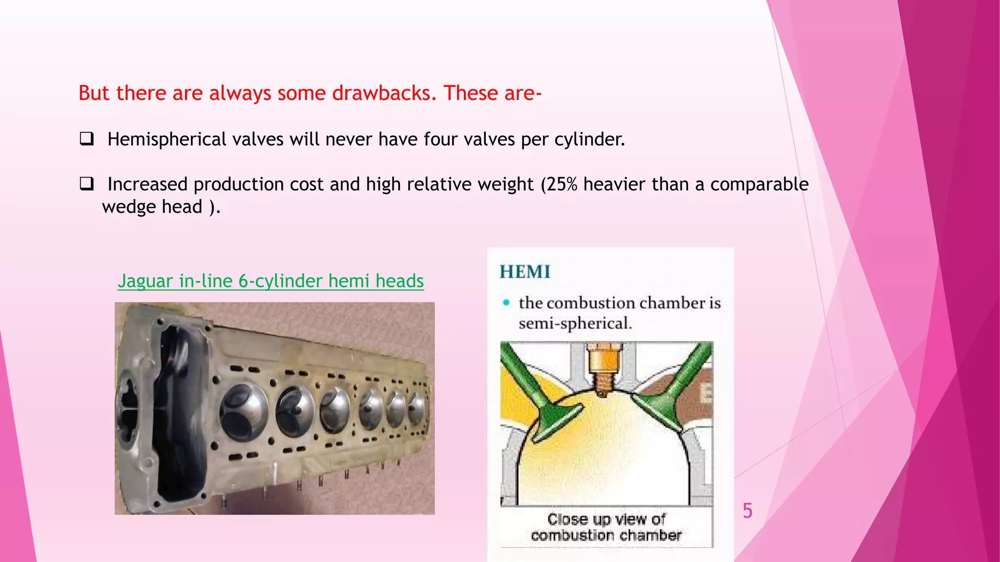
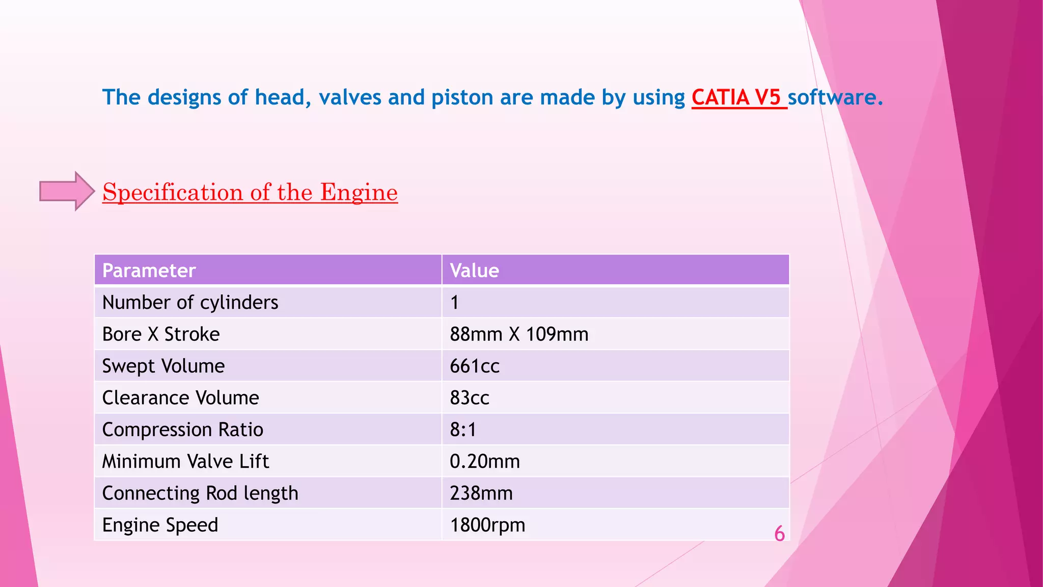
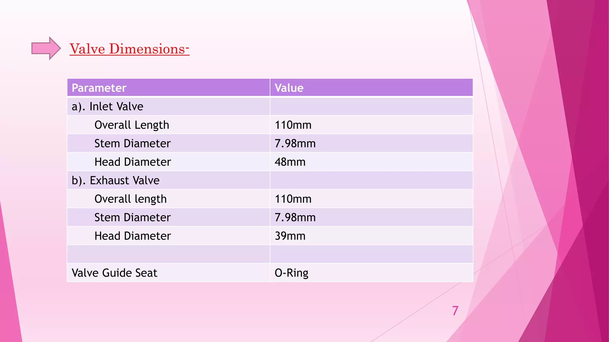
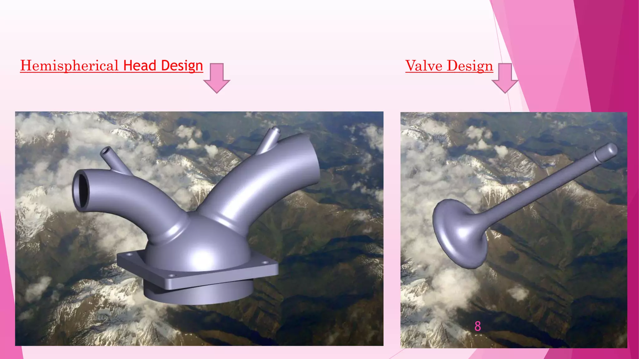
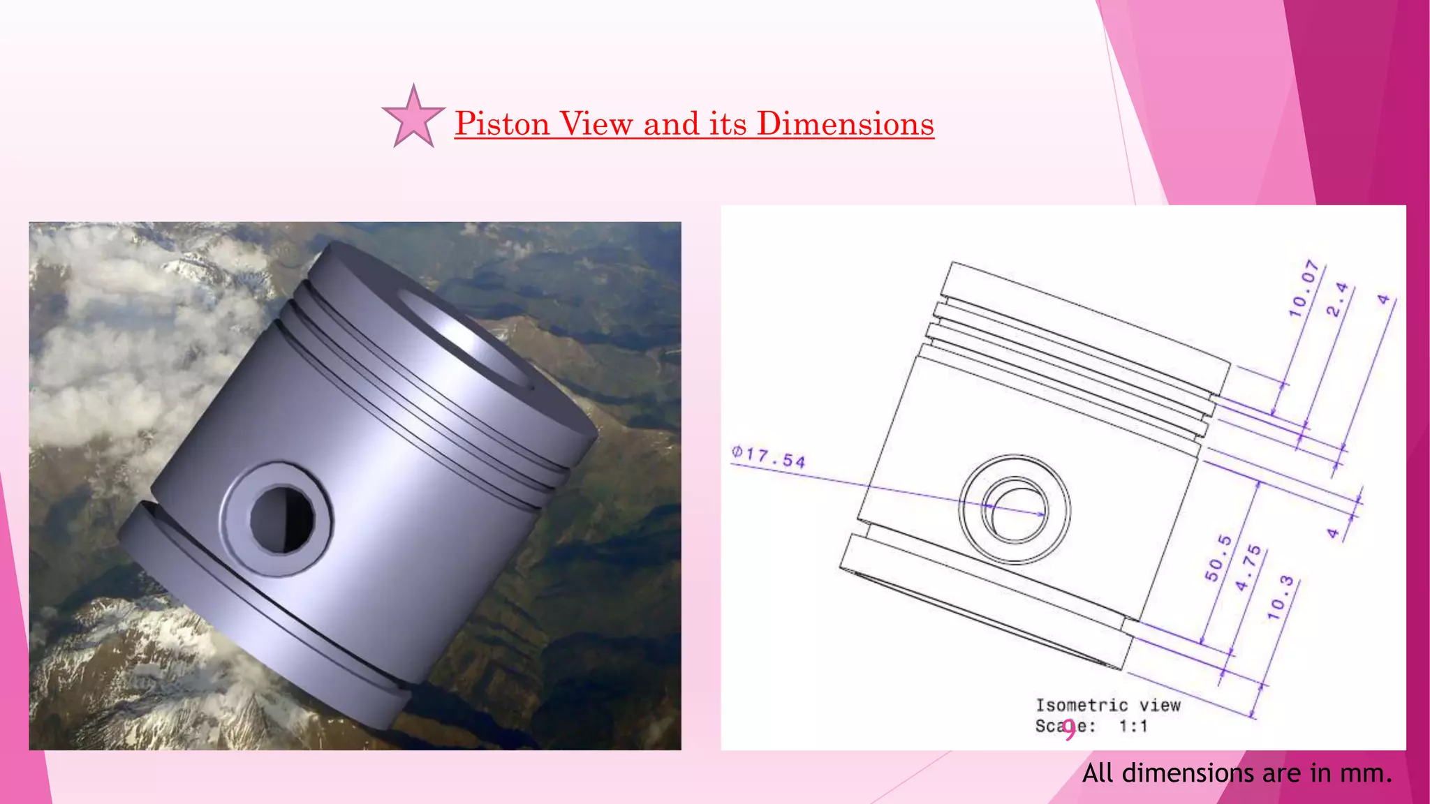
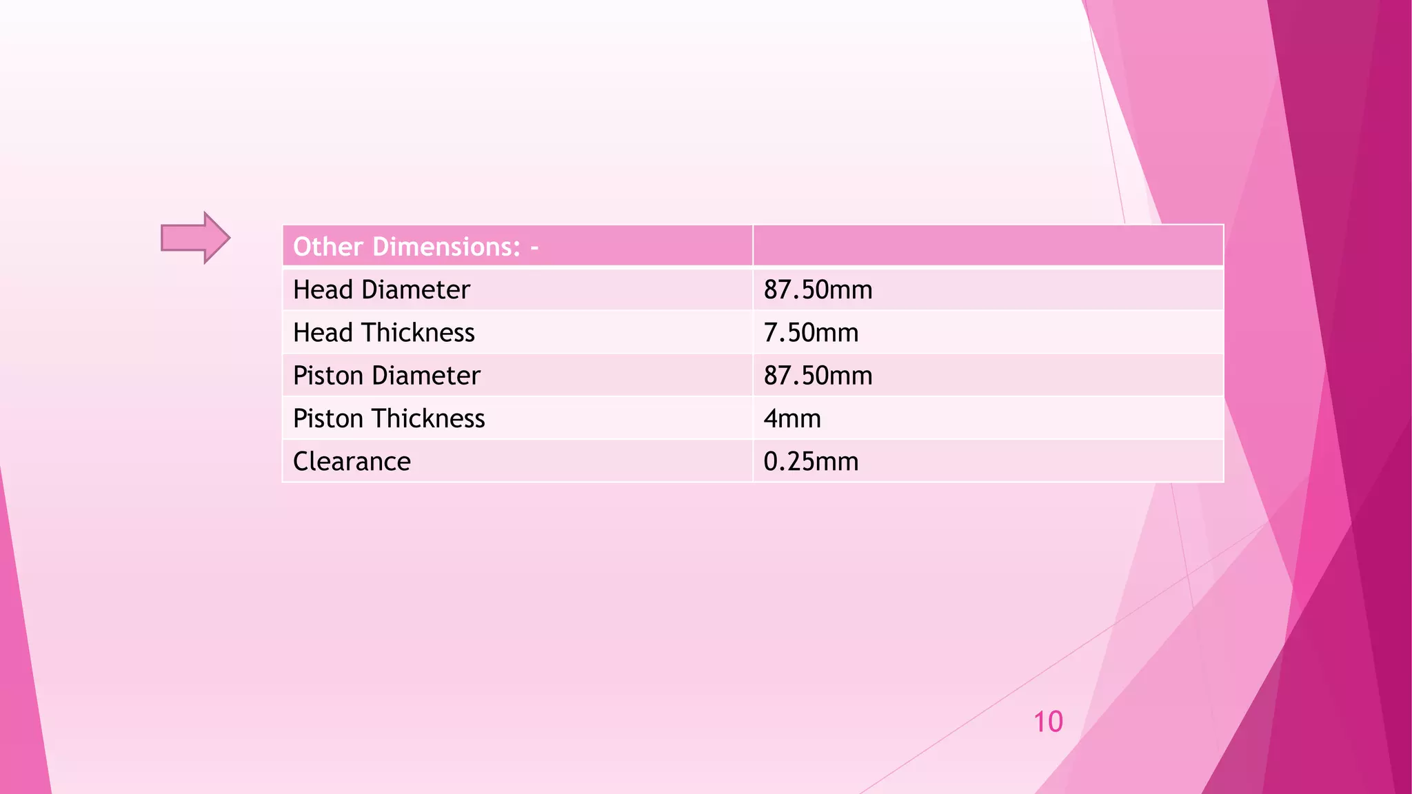
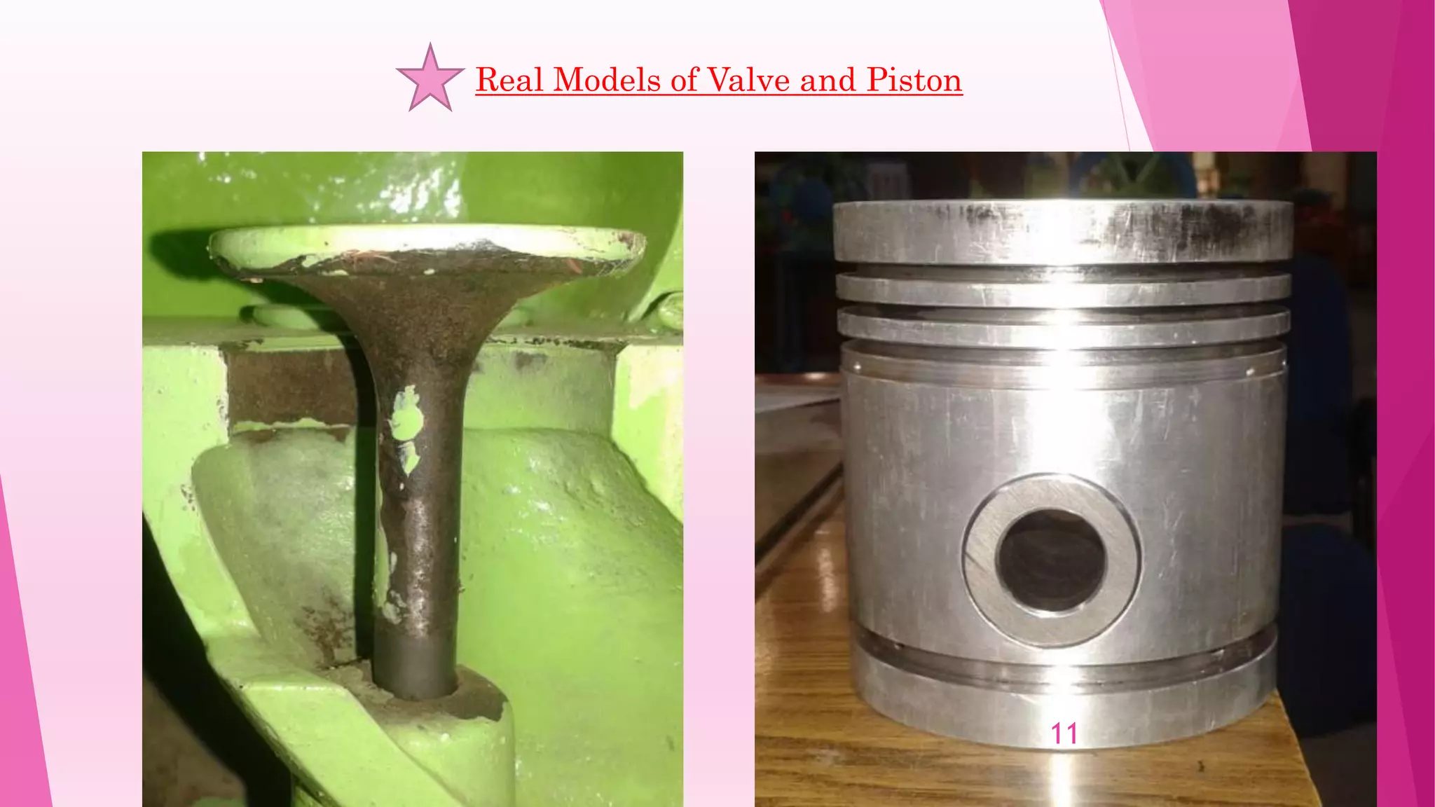
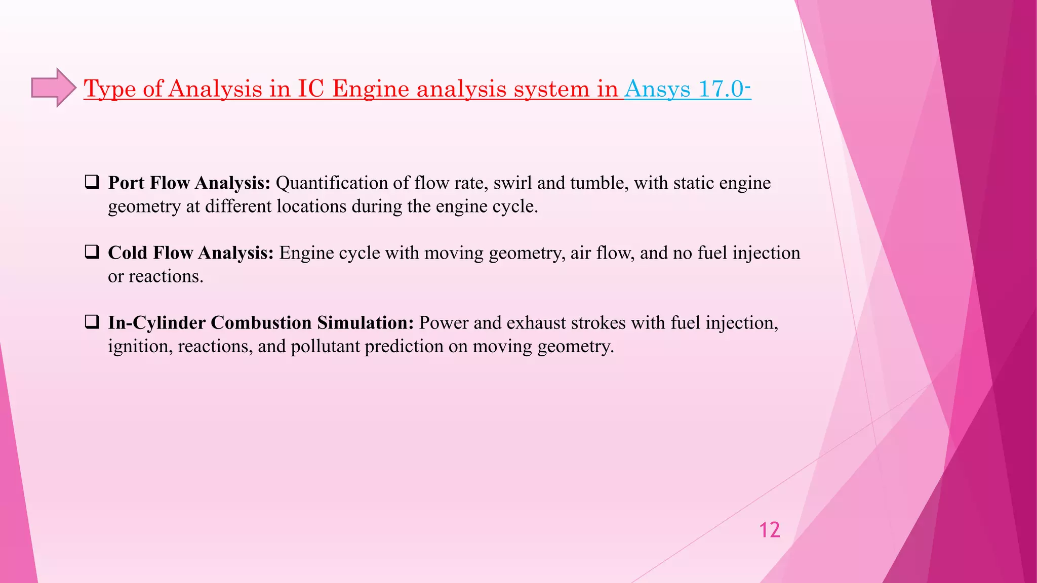
Study and Performance Analysis of
combustion chamber using ANSYS
Project Mentor
Dr. Nilanjan Mallik Gyanendra Awasthi (13135043)
Jatin Kumar Chaudhari (13135048)
Group Members
1
The primary design decisions are
 The specification for engine type
 Peak power at a specified speed or RPM
 The number of cylinders
 Fuel and emission characteristics
 The total volume of the engine
 Overall packaging of the system including all the subsystems
Engine Design
These design decisions impact the computation of the amount of air and fuel needed by
the engine and lead to a cascade of design decisions to maximize the overall efficiency of
the engine.
2
Combustion Chamber:
 An enclosure in which combustion, especially of a fuel or propellant, is initiated and controlled.
The mixture of fuel + air(oxygen) + residual gases combust inside the chamber when the
Temperature increased to the ignition temperature of the fuel.
 There are various kinds of combustion chamber having different benefits and limitations:
 Hemispherical head combustion chamber
 Wedge head combustion chamber
 Disc head combustion chamber
 Pent-roof combustion chamber
3
We have chosen Hemispherical Head combustion chamber for the analysis and canted valve
design.
Why did we choose?
 Hemispherical head gives an combustion chamber with minimal heat loss to the head.
 It allows for large head of two valves.
 good volumetric efficiency is also achieved due to improved fuel flow.
4
But there are always some drawbacks. These are-
 Hemispherical valves will never have four valves per cylinder.
 Increased production cost and high relative weight (25% heavier than a comparable
wedge head ).
Jaguar in-line 6-cylinder hemi heads
5
Parameter Value
Number of cylinders 1
Bore X Stroke 88mm X 109mm
Swept Volume 661cc
Clearance Volume 83cc
Compression Ratio 8:1
Minimum Valve Lift 0.20mm
Connecting Rod length 238mm
Engine Speed 1800rpm
Specification of the Engine
The designs of head, valves and piston are made by using CATIA V5 software.
6
Parameter Value
a). Inlet Valve
Overall Length 110mm
Stem Diameter 7.98mm
Head Diameter 48mm
b). Exhaust Valve
Overall length 110mm
Stem Diameter 7.98mm
Head Diameter 39mm
Valve Guide Seat O-Ring
Valve Dimensions-
7
Hemispherical Head Design Valve Design
8
Piston View and its Dimensions
All dimensions are in mm.
9
Other Dimensions: -
Head Diameter 87.50mm
Head Thickness 7.50mm
Piston Diameter 87.50mm
Piston Thickness 4mm
Clearance 0.25mm
10
Real Models of Valve and Piston
11
 Port Flow Analysis: Quantification of flow rate, swirl and tumble, with static engine
geometry at different locations during the engine cycle.
 Cold Flow Analysis: Engine cycle with moving geometry, air flow, and no fuel injection
or reactions.
 In-Cylinder Combustion Simulation: Power and exhaust strokes with fuel injection,
ignition, reactions, and pollutant prediction on moving geometry.
Type of Analysis in IC Engine analysis system in Ansys 17.0-
12
Cold Flow Simulation:
 goal is to capture the mixture formation process by accurately accounting for the interaction of
moving geometry with the fluid dynamics of the induction process.
 Stages of IC Flow Simulation-
a). Simulation of the engine is started by importing the geometry
b). Imported geometry is divided into small volumes and sub-volumes before meshing.
c). Decompose the geometry into different zones and mesh them properly.
d). Each volume will be meshed into hex or tet elements.
 Non-conformal interface is used to completely shut the valve.
13
IC Engine alaysis system in Ansys-
14
Work done on Ansys till now-
15
Main objectives-
 The primary goal of engine design is to maximize each efficiency factor, in order to extract the
most power from the least amount of fuel. In terms of fluid dynamics, the volumetric and
combustion efficiency are dependent on the fluid dynamics in the engine manifolds and cylinders.
Efficiency factors are indicated efficiency, brake efficiency, mechanical efficiency, volumetric
efficiency, combustion efficiency.
 The second goal of engine design is to meet emissions requirements, which are always specified by
regulations. The pollutants include oxides of nitrogen, sulfur oxides (SOx), CO (carbon monoxide),
unburned hydrocarbons (HC), and Poly Aromatic Hydrocarbons (PAH or “soot”), which are all
products of the combustion process.
16
References-
 ANSYS 14.0 Library
 S. Parimala Murugaveni, P. Mohamed Shameer ; “ANALYSIS OF FORCED DRAFT COOLING
TOWER PERFORMANCE USING ANSYS FLUENT SOFTWARE” ; International Journal of
Research in Engineering and Technology e-ISSN: 2319-1163 | p-ISSN: 2321-7308
 Rohith.S, Dr. G .V. Naveen Prakash; “Cold Flow simulation in IC Engine” ; International
Research Journal of Engineering and Technology (IRJET); e-ISSN: 2395 -0056 p-ISSN: 2395-
0072
17
18
Thank You

Study and performance analysis of combustion chamber using ANSYS

  • 1.
    Study and PerformanceAnalysis of combustion chamber using ANSYS Project Mentor Dr. Nilanjan Mallik Gyanendra Awasthi (13135043) Jatin Kumar Chaudhari (13135048) Group Members 1
  • 2.
    The primary designdecisions are  The specification for engine type  Peak power at a specified speed or RPM  The number of cylinders  Fuel and emission characteristics  The total volume of the engine  Overall packaging of the system including all the subsystems Engine Design These design decisions impact the computation of the amount of air and fuel needed by the engine and lead to a cascade of design decisions to maximize the overall efficiency of the engine. 2
  • 3.
    Combustion Chamber:  Anenclosure in which combustion, especially of a fuel or propellant, is initiated and controlled. The mixture of fuel + air(oxygen) + residual gases combust inside the chamber when the Temperature increased to the ignition temperature of the fuel.  There are various kinds of combustion chamber having different benefits and limitations:  Hemispherical head combustion chamber  Wedge head combustion chamber  Disc head combustion chamber  Pent-roof combustion chamber 3
  • 4.
    We have chosenHemispherical Head combustion chamber for the analysis and canted valve design. Why did we choose?  Hemispherical head gives an combustion chamber with minimal heat loss to the head.  It allows for large head of two valves.  good volumetric efficiency is also achieved due to improved fuel flow. 4
  • 5.
    But there arealways some drawbacks. These are-  Hemispherical valves will never have four valves per cylinder.  Increased production cost and high relative weight (25% heavier than a comparable wedge head ). Jaguar in-line 6-cylinder hemi heads 5
  • 6.
    Parameter Value Number ofcylinders 1 Bore X Stroke 88mm X 109mm Swept Volume 661cc Clearance Volume 83cc Compression Ratio 8:1 Minimum Valve Lift 0.20mm Connecting Rod length 238mm Engine Speed 1800rpm Specification of the Engine The designs of head, valves and piston are made by using CATIA V5 software. 6
  • 7.
    Parameter Value a). InletValve Overall Length 110mm Stem Diameter 7.98mm Head Diameter 48mm b). Exhaust Valve Overall length 110mm Stem Diameter 7.98mm Head Diameter 39mm Valve Guide Seat O-Ring Valve Dimensions- 7
  • 8.
  • 9.
    Piston View andits Dimensions All dimensions are in mm. 9
  • 10.
    Other Dimensions: - HeadDiameter 87.50mm Head Thickness 7.50mm Piston Diameter 87.50mm Piston Thickness 4mm Clearance 0.25mm 10
  • 11.
    Real Models ofValve and Piston 11
  • 12.
     Port FlowAnalysis: Quantification of flow rate, swirl and tumble, with static engine geometry at different locations during the engine cycle.  Cold Flow Analysis: Engine cycle with moving geometry, air flow, and no fuel injection or reactions.  In-Cylinder Combustion Simulation: Power and exhaust strokes with fuel injection, ignition, reactions, and pollutant prediction on moving geometry. Type of Analysis in IC Engine analysis system in Ansys 17.0- 12
  • 13.
    Cold Flow Simulation: goal is to capture the mixture formation process by accurately accounting for the interaction of moving geometry with the fluid dynamics of the induction process.  Stages of IC Flow Simulation- a). Simulation of the engine is started by importing the geometry b). Imported geometry is divided into small volumes and sub-volumes before meshing. c). Decompose the geometry into different zones and mesh them properly. d). Each volume will be meshed into hex or tet elements.  Non-conformal interface is used to completely shut the valve. 13
  • 14.
    IC Engine alaysissystem in Ansys- 14
  • 15.
    Work done onAnsys till now- 15
  • 16.
    Main objectives-  Theprimary goal of engine design is to maximize each efficiency factor, in order to extract the most power from the least amount of fuel. In terms of fluid dynamics, the volumetric and combustion efficiency are dependent on the fluid dynamics in the engine manifolds and cylinders. Efficiency factors are indicated efficiency, brake efficiency, mechanical efficiency, volumetric efficiency, combustion efficiency.  The second goal of engine design is to meet emissions requirements, which are always specified by regulations. The pollutants include oxides of nitrogen, sulfur oxides (SOx), CO (carbon monoxide), unburned hydrocarbons (HC), and Poly Aromatic Hydrocarbons (PAH or “soot”), which are all products of the combustion process. 16
  • 17.
    References-  ANSYS 14.0Library  S. Parimala Murugaveni, P. Mohamed Shameer ; “ANALYSIS OF FORCED DRAFT COOLING TOWER PERFORMANCE USING ANSYS FLUENT SOFTWARE” ; International Journal of Research in Engineering and Technology e-ISSN: 2319-1163 | p-ISSN: 2321-7308  Rohith.S, Dr. G .V. Naveen Prakash; “Cold Flow simulation in IC Engine” ; International Research Journal of Engineering and Technology (IRJET); e-ISSN: 2395 -0056 p-ISSN: 2395- 0072 17
  • 18.