
Downloaded 870 times

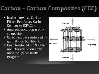
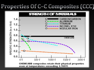
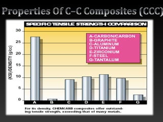
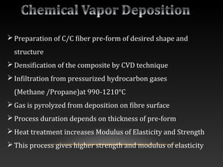

Carbon-carbon composites are composites with carbon fiber reinforcement and a carbon matrix. They offer high strength and can withstand very high temperatures up to 3000°C. The fibers and matrix are both carbon, resulting in low density, high thermal conductivity, and strength retention even at elevated temperatures. However, carbon-carbon composites also have some limitations like high fabrication costs and poor oxidation resistance.


![Getting Started with Apache Spark: Big Data Made Simple [Free Meetup]](https://cdn.slidesharecdn.com/ss_thumbnails/apachesparkgettingstarted-260203175547-8361bcc3-thumbnail.jpg?width=640&height=640&fit=bounds)