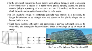
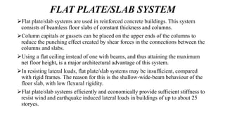
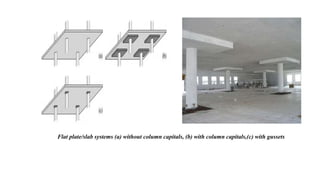
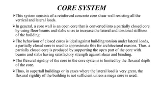
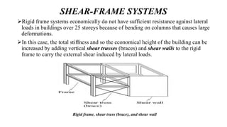
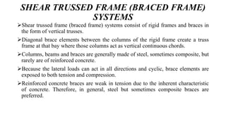
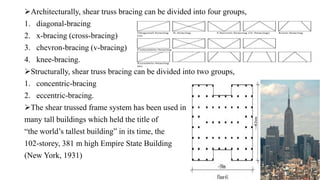
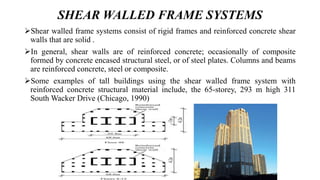
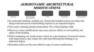
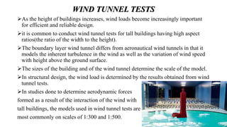
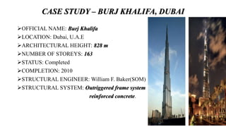
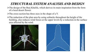
SlideShare a Scribd company logo
STURCTUAL SYSTEMS AND
AERODYNAMICS IN MULTI-STOREY
BUILDINGS
BY
MANOJ KUMAR. M
4PS16CCS07
UNDER THE GUIDENCE OF
DR.B.S.JAYASHANKARBABU SIR
P.E.S COLLEGE OF ENGINEERING,MANDYA
CIVIL ENGINEERING(CAD OF STRUCTURES)
CONTENTS
 INTRODUCTION
 LATERAL LOADS AFFECTED MULTI-STOREY BUILDINGS
 STRUCTURAL SYSTEMS OF MULTI-STOREY BULIDINGS
 AERODYNAMICS IN MULTI-STOREY BUILDINGS
 CASE SUTDY
 CONCLUSION
 REFERENCES
INTRODUCTION
 The continuing economic prosperity and population increase in the urban
areas point toward a future with increased activity in high-rise construction
of residential and office buildings.
 However, construction of high-rise buildings can be economically attractive
only if the structural engineers can have comprehensive understanding of
the structural behaviours of various structural systems and the practical
sense of the construction problems.
 Fazlur Rahman Khan, initiated important structural systems for
skyscrapers Considered the “father of tubular designs” for high-rises, Khan
was also a pioneer in computer-aided design (CAD).
He has been called the “Einstein of structural engineering” and the
“Greatest Structural Engineer of the 20th Century” for his innovative use
of structural systems that remain fundamental to modern skyscraper design
and construction.
LATERAL LOADS AFFECTING MULTI-
STOREY BULIDINGS
From the structural design point of view, tall (high-rise) buildings, because
of their extraordinary height, show a greater sensitivity to,
Wind Load
Earthquake induced lateral loads than low-rise buildings.
The wind loads affecting the building and the response of the building depend on the
following factors:
1. The characteristics of the wind
2. The building size and geometry
3. The stiffness of the building and the distribution of the building mass
4. The inherent damping characteristics of the structural system and of the construction
material, which dissipates wind-induced building sway
5. The surrounding topography (issues with neighbouring buildings, etc.)
6. The orientation (position) of the building with respect to the prevailing wind direction.
Earthquakes are the propagation of energy released as seismic waves in the earth
when the earth’s crust cracks, or when sudden slippage occurs along the cracks
because of the movement of the earth’s tectonic plates relative to one another.
The magnitude of the lateral force (F) on a structure formed by the effect of an
earthquake depends on the structure’s mass (m), the ground acceleration (a) and
the structure’s dynamic characteristics (F α ma).
As the height of a structure increases, the flexibility also increases and the
acceleration is expected to be less than in low-rise structures (F<ma); however,
for structures whose natural period is close to that of the seismic waves, in
earthquakes of long duration, the lateral force (F) affecting the structure may be
larger than the mass of the structure multiplied by the ground acceleration (F>ma)
THE STRUCTURAL SYSTEMS OF MULTI-
STOREY BUILDINGS
Tall building structural systems:
1. Rigid frame systems
2. Flat plate/slab systems
3. Core systems
4. Mega core system
5. Shear wall systems
6. Shear-frame systems
7. Mega column (mega frame, space truss) systems
8. Outriggered frame systems
9. Tube systems.
RIGID FRAME SYSTEM
Rigid frame systems, also called moment frame systems, are used in steel and
reinforced concrete buildings.
A rigid frame is an unbraced frame that can resist both vertical and lateral loads by
the bending of beams and columns.
Reinforced concrete is an ideal material for this system by its naturally monolithic
behaviour, resulting with inherent rigidity at connections.
The structural stiffness of rigid frames is directly proportional to the cross-
sectional dimensions and bending rigidity of the beams and columns, and
inversely proportional to their length and spacing.
For buildings constructed in regions of high seismic activity the details of the
connections between structural elements are very important because of the need
for ductile behaviour in the rigid frame due to the large lateral drift during severe
earthquakes.
In the structural engineering beam theory term, plastic hinge, is used to describe
the deformation of a section of a beam where plastic bending occurs. the plastic
moment (Mp) is a property of a structural section. It is defined as the moment at
which the entire cross section has reached its yield stress.
In the structural design of reinforced concrete rigid frames, it is necessary to
design the columns to be stronger than the beams so that plastic hinges can be
formed in the beams.
Rigid frame systems efficiently and economically provide sufficient stiffness to
resist wind and earthquake induced lateral loads in buildings of up to about 25
storeys.
The 21-storey, 94 m high Lever House (New York, 1952)Rigid frame system
FLAT PLATE/SLAB SYSTEM
Flat plate/slab systems are used in reinforced concrete buildings. This system
consists of beamless floor slabs of constant thickness and columns.
Column capitals or gussets can be placed on the upper ends of the columns to
reduce the punching effect created by shear forces in the connections between the
columns and slabs.
Using a flat ceiling instead of one with beams, and thus attaining the maximum
net floor height, is a major architectural advantage of this system.
In resisting lateral loads, flat plate/slab systems may be insufficient, compared
with rigid frames. The reason for this is the shallow-wide-beam behaviour of the
floor slab, with low flexural rigidity.
Flat plate/slab systems efficiently and economically provide sufficient stiffness to
resist wind and earthquake induced lateral loads in buildings of up to about 25
storyes.
Flat plate/slab systems (a) without column capitals, (b) with column capitals,(c) with gussets
CORE SYSTEM
This system consists of a reinforced concrete core shear wall resisting all the
vertical and lateral loads.
In general, a core wall is an open core that is converted into a partially closed core
by using floor beams and slabs so as to increase the lateral and torsional stiffness
of the building.
The behaviour of closed cores is ideal against building torsion under lateral loads,
a partially closed core is used to approximate this for architectural reasons. Thus, a
partially closed core is produced by supporting the open part of the core with
beams and slabs having satisfactory strength against shear and bending.
The flexural rigidity of the core in the core systems is limited by the flexural depth
of the core.
Thus, in supertall buildings or in cases where the lateral load is very great, the
flexural rigidity of the building is not sufficient unless a mega core is used.
Core systems efficiently and economically provide sufficient
stiffness to resist wind and earthquake induced lateral loads in
buildings of up to about 20 storeys.
In core systems, floor slabs are cantilevered from
the core shear wall independently, or else cantilevered
modules of floor slabs are used.
In the case of cantilevered modules, floor slabs, except the bottom
slab of each module, are cantilevered from the core shear wall and
are supported by discontinuous perimeter columns down through
the height of the modules.
The bottom slab of each module is a strengthened cantilever
floor slab which supports the perimeter columns of the upper
storeys in the module.
Slabs in core systems: (a) cantilever
slabs,(b) strengthened cantilever slab
MEGA CORE SYSTEMS
Mega core systems consist of reinforced concrete or composite core shear walls
with much larger cross-sections than normal, running continuously throughout the
height of the building.
Since the mega core can resist all vertical and lateral loads in this system, there is
no need for columns or shear walls on the perimeter of the building.
In mega core systems, floor slabs are cantilevered from the core shear wall, Mega
core systems can also be used with strengthened cantilever slabs.
Slabs in the mega core system: (a) cantilever slab, (b) supported
cantilever slab
Mega core systems efficiently and economically provide sufficient stiffness to
resist wind and earthquake induced lateral loads in buildings of more than 40
storeys.
Examples of tall buildings using the mega core system with reinforced concrete
structural. The 52-storey, 235 m high 8 Shenton Way (Singapore, 1986).
Which has a reinforced concrete core shear wall having circular cross-section with
an external diameter of 25 m and thickness varying between 1.65 to 1 m (from
bottom to top)
SHEAR WALL SYSTEMS
This system consists of reinforced concrete shear walls, which can be perforated
(with openings) or solid.
Shear wall systems can be thought of as a vertical cantilever rigidly fixed at the
base, and can resist all vertical and lateral loads on a building without columns.
Owing to the nature of cantilever behaviour, the inter-storey drift between
adjacent floors is greater in the upper floors than in the other floors.
For this reason, in supertall buildings it is difficult
to control the lateral drift at the building top.
Shear wall systems efficiently and economically
provide sufficient stiffness to resist wind and
earthquake induced lateral loads in buildings of up
to about 35 storeys.
SHEAR-FRAME SYSTEMS
Rigid frame systems economically do not have sufficient resistance against lateral
loads in buildings over 25 storeys because of bending on columns that causes large
deformations.
In this case, the total stiffness and so the economical height of the building can be
increased by adding vertical shear trusses (braces) and shear walls to the rigid
frame to carry the external shear induced by lateral loads.
Rigid frame, shear truss (brace), and shear wall
SHEAR TRUSSED FRAME (BRACED FRAME)
SYSTEMS
Shear trussed frame (braced frame) systems consist of rigid frames and braces in
the form of vertical trusses.
Diagonal brace elements between the columns of the rigid frame create a truss
frame at that bay where those columns act as vertical continuous chords.
Columns, beams and braces are generally made of steel, sometimes composite, but
rarely are of reinforced concrete.
Because the lateral loads can act in all directions and cyclic, brace elements are
exposed to both tension and compression.
Reinforced concrete braces are weak in tension due to the inherent characteristic
of concrete. Therefore, in general, steel but sometimes composite braces are
preferred.
Architecturally, shear truss bracing can be divided into four groups,
1. diagonal-bracing
2. x-bracing (cross-bracing)
3. chevron-bracing (v-bracing)
4. knee-bracing.
Structurally, shear truss bracing can be divided into two groups,
1. concentric-bracing
2. eccentric-bracing.
The shear trussed frame system has been used in
many tall buildings which held the title of
“the world’s tallest building” in its time, the
102-storey, 381 m high Empire State Building
(New York, 1931)
SHEAR WALLED FRAME SYSTEMS
Shear walled frame systems consist of rigid frames and reinforced concrete shear
walls that are solid .
In general, shear walls are of reinforced concrete; occasionally of composite
formed by concrete encased structural steel, or of steel plates. Columns and beams
are reinforced concrete, steel or composite.
Some examples of tall buildings using the shear walled frame system with
reinforced concrete structural material include, the 65-storey, 293 m high 311
South Wacker Drive (Chicago, 1990)
MEGA COLUMN SYSTEMS
Mega column systems consist of reinforced concrete or composite columns and
shear walls with much larger cross-sections than normal, running continuously
throughout the height of the building.
In this system, mega columns and mega shear walls can resist all the vertical and
lateral loads.
Due to the probable insufficiency of floor slabs acting as rigid floor diaphragms,
to support this behaviour of restraining the columns laterally, belts, vierendeel
frames, and mega braces are used.
In this way, all external mega columns and/or shear walls are connected to
participate in the lateral stiffness of the structure.
Mega columns can also be used solely to provide large spaces at the building
entrance, as an aid to the main structural system for the levels above the entrance,
without running continuously throughout the height of the building.
As the number of mega columns at the entrance is much lower than the number of
columns on the upper storeys, the structural transition between them is achieved
using deep transfer beams.
In such cases, the cross-sectional dimensions of the column at the entrance are
large enough for it to be classified as a “mega column”, but the structural system
cannot be classified as a “mega column system”.
Cheung Kong Centre, Hong Kong, China, 1999
OUTRIGGERED FRAME SYSTEMS
Outriggered frame systems have been developed by adding outriggers to shear-
frame systems with core (core-frame systems) to couple the core with the
perimeter (exterior) columns.
The outriggers are structural elements connecting the core to the perimeter
columns at one or more levels throughout the height of the building to stiffen the
structure.
This structural element is a horizontal extension of the core shear truss/wall to the
perimeter columns in the form of a knee.
Outriggered frame system
The outriggers, which are connected rigidly to the core and by hinges to the
perimeter columns, increase the effective flexural depth and so the flexural
stiffness of the system in the direction of bending under lateral loads by enabling
the core to receive support from the perimeter columns.
Outrigger to perimeter column connections: (a) rigid connection,
(b) hinged connection
TUBE SYSTEMS
The tube system was innovated in the early 1960s by the famous structural
engineer Fazlur Rahman Khan who is considered the “father of tubular design”.
This system is evolved from the rigid frame system and can be defined as a three-
dimensional rigid frame having the capability of resisting all lateral loads with the
facade structure.
In tubular design, the rigidity of the structural system against lateral loads can be
increased with solutions such as:
1. Closer spacing of the perimeter columns
2. Increasing the depth of the spandrel beams connected to the perimeter columns
3. Adding shear trusses/braces or shear walls to the core
4. Adding an inner tube in place of the core (tube-in-tube)
5. Adding a truss (multi-storey braces) to the building exterior (trussed-tube)
6. Combining more than one tube (bundled-tube).
Tube systems can be divided into three types:
1. Framed-tube systems
2. Trussed-tube systems
3. Bundled-tube systems.
The closely spaced perimeter/exterior columns, which are usually spaced at 1.5 to
4.5 m centres, connected by deep spandrel beams at floor levels.
Closely spaced perimeter columns can obstruct the panoramic exterior view from
inside the building.
As a solution, with the aim of preventing the difficulties of access experienced
when passing through these spaces at the building entrance, deep transfer arches
or beams can be used or branching columns can be used.
Below the transfer levels formed by transfer beams and branching columns,
closely spaced columns are replaced with widely spaced columns.
Framed-tube systems
Configurations of the ground floor in the framed-tube system
World Trade Center Twin Towers, New York, USA, 1972
In order to increase the spacing between the columns without inhibiting the
tubular behaviour, connecting the perimeter columns with exterior multi-storey
braces led to the development of the trussed-tube (braced-tube) system.
 In buildings with steel or composite trussed-tube systems, multi-storey braces are
used on the facade of the building.
In the case of buildings with reinforced concrete trussed-tube systems, spaces
between the columns are filled with reinforced concrete shear walls to form multi-
storey diagonal or X-brace pattern on the exterior of the building.
Trussed-tube systems
Trussed-tube system: (a) Steel or composite,
(b) Reinforced concrete
John Hancock Center, Chicago, USA, 1969
Bundled-tube systems are a combination of more than one tube (framed-tube and
trussed-tube) acting together as a single tube.
As the heights of buildings increase, in general their aspect ratios also increase.
The increase in the aspect ratio increases the slenderness and flexibility of the
building, and thus its lateral drift.
In order to keep control of the aspect ratio, it is necessary to increase the cross-
sectional dimensions of the base, which affects the denominator in this ratio.
Thus, in bundled-tube systems, the increase in the cross-sectional dimensions at
the ground floor in order to control the slenderness of the building makes it
possible to reduce the cross-sectional dimensions by different amounts throughout
the height of the building.
Bundled-tube systems
Willis Tower, Chicago, USA, 1974
AERODYANAMICS IN MULTI-STOREY
BUILDINGS
AREODYANAMICS is the study of the properties of moving air and the
interaction between the air and solid bodies moving through it.
Wind-induced building motion can essentially be divided into three types,
1. Along-wind motion
2. Across-wind motion
3. Torsional motion.
Tall building motions under the effect of wind
VORTEX SHEDDING EFFECT
 The along-wind motion, across-wind motion occurs, which is usually
more decisive and critical.
 Thus, while the windward face of the building is subject to positive wind
pressure and the leeward face is subject to negative wind pressure
(suction), the across-wind faces of the building are subject to alternating
negative wind pressure.
DESIGN AGAINST WIND LOADING
Wind loads, which cause large lateral drift, play a decisive role in the design of tall
buildings and can be even more critical than earthquake loads.
As a result, the wind loads and lateral drift to which tall buildings are subject have
become an important problem.
BUILDING ORIENTATION AND SHAPE
Orienting (positioning) the building according to the prevailing wind direction is
an effective design approach for reducing wind loads.
A reduction of between 10–20 per-cent of the across-wind building response can
be obtained by rotating the building to within 10º of the wind direction.
The effectiveness of this approach is dependent on both the wind climate at the
project site and the shape of the building.
In this context, cylindrical, elliptical, conical and twisted forms can be accepted
among the efficient building forms.
The largest lateral drift value exhibited by a building with a circular plan under
wind loads is approximately half of the lateral drift value exhibited by a building
with a square plan.
Due to the facade channels made possible by the twisted form, the effect of wind
on the building is neatly blocked by breaking up the wind flow. Thus, wind-
induced lateral loads are reduced.
PLAN VARIATION
Varying the building plan results from the variation in plan dimensions or shape
throughout the height of the building and can be achieved by:
1. reducing the plan area
2. changing the plan shape.
Plan variation by reducing the plan area toward the top of the building results in a
reduction in the surface area affected by the wind at the upper levels of the
building, which lessens the wind intensity and thus the excess pressure.
 The reduction in the plan area of the building as it rises can be in the form of:
1. Tapering
2. Setbacks.
Some examples of buildings with tapering and setbacks
An analytical study by Khan (1972) has shown that, by creating a slope of 8 per
cent in the facade of a 40-storey building, a 50 per cent reduction of the lateral
drift in the upper stories can be obtained.
Varying the plan by changing the plan shape at various levels throughout the
height of the building causes a corresponding change in the vortex shedding effect.
STRUCTURE-BASED DESIGN
Buildings with symmetrical plan forms exhibit greater structural efficiency under
lateral loads than buildings with asymmetrical plan forms.
A building with a rectangular plan exhibits greater sensitivity to wind loads than
buildings with circular, elliptical, or triangular plans.
Curved or zig-zag plans can also be used to increase the stiffness of the building
against lateral loads.
MECHANICAL DESIGN APPROACH
In designing tall buildings, engineers assume a certain level of inherent damping
in the structure when estimating the serviceability of the building under wind and
earthquake-induced lateral loads.
Because the inherent damping capacity of buildings is often insufficient and
difficult to estimate, auxiliary damping systems, the mechanical design approach
are used to reduce the effects of wind-induced vibration.
These systems, known as “dampers”, are mechanisms used to slow the lateral
movement and reduce its magnitude and dampen the building sway by influencing
the phases of force and displacement.
The principle of creating drift in the opposite direction
to the lateral drift of the building by creating a counteracting
inertia force “Tuned mass dampers” (TMDs) are an example
of this kind of system in Taipei 101.
AERODYNAMIC ARCHITECTURAL
MODIFICATIONS
In a prismatic building, notched, cut, slotted and rounded corners can reduce the
along-wind and across-wind building response to an important degree.
The corner softening should extend about 10% of the building width.
However, corner modifications may cause adverse effects in serviceability and
safety of the building.
When comparing saw-tooth corners which are a development of recessed corners
with sharp corners, they reduce the wind load affecting the building to an
important degree.
Rounded corners are the most effective type of corner modification.
WIND TUNNEL TESTS
As the height of buildings increases, wind loads become increasingly important
for efficient and reliable design.
it is common to conduct wind tunnel tests for tall buildings having high aspect
ratios(the ratio of the width to the height).
The boundary layer wind tunnel differs from aeronautical wind tunnels in that it
models the inherent turbulence in the wind as well as the variation of wind speed
with height above the ground surface.
The sizes of the building and of the wind tunnel determine the scale of the model.
In structural design, the wind load is determined by the results obtained from wind
tunnel tests.
In studies done to determine aerodynamic forces
formed as a result of the interaction of the wind with
tall buildings, the models used in wind tunnel tests are
most commonly on scales of 1:300 and 1:500.
CASE STUDY – BURJ KHALIFA, DUBAI
OFFICIAL NAME: Burj Khalifa
LOCATION: Dubai, U.A.E
ARCHITECTURAL HEIGHT: 828 m
NUMBER OF STOREYS: 163
STATUS: Completed
COMPLETION: 2010
STRUCTURAL ENGINEER: William F. Baker(SOM)
STRUCTURAL SYSTEM: Outriggered frame system
reinforced concrete.
STRUCTURAL SYSTEM ANALYSIS AND DESIGN
The design of the Burj Khalifa, which derives its main inspiration from the form
of a local desert flower.
The cross-section has three axes in the shape of a Y.
The reduction of the plan area by using setbacks throughout the height of the
building, also reduces wind forces at the upper levels by a reduction in the surface
area affected by the wind.
The structural system of the Burj Khalifa is composed of a hexagonal central core
(buttressed by wing shear walls) and outriggers.
Each wing has hammerhead ended corridor shear walls (extending from the central
core), perimeter shear walls at the sides and circular nose columns at the tip.
Outriggers connect the core with the perimeter shear walls and nose columns
through buttresses (wing shear walls).
The hexagonal central core consists of reinforced concrete shear walls with
thicknesses varying between 130 cm at the bottom to 50 cm at the top through the
height of the building.
The slab system on each storey consists of two-way reinforced concrete flat plates
that vary between 20 and 30 cm in depth, while on the upper storeys they vary
between 22.5 and 25 cm in depth.
• The central hexagonal reinforced concrete core wall provide the torsional
resistance of the structure similar to a closed tube or axle.
• The central hexagonal walls are buttressed by the wing walls and hammer head
wall which behave as the web and flange of a beam to resist the wind shear and
moments.
• Outrigged allow the columns to participate in the lateral load resistance of the
structure.
After each round of wind tunnel testing, the data was analyzed and the building
was reshaped to minimize wind effects and accommodate unrelated changes.
In general, the number and spacing of the setbacks changed as did the shape of
wings.
This process resulted in a substantial reduction in wind forces on the tower by
“confusing” the wind, by encouraging disorganized vortex shedding over the
height of the Tower.
CONCLUSION
1. This topic has presented a general review of structural systems for tall buildings.
2. Various structural systems within each category of the new classification have
been described with emphasis on innovations.
3. For the future megastructures in megacities, it is expected that the building
height will be continuously increased in conjunction with the improvements in
technology in structural systems, materials, energy efficiency, and damping
systems.
4. Efficient structural systems in seismic zones also need to be further investigated.
5. Tall rectangular building cause most aerodynamic problem due to height and
circular, tapered, multi-sided building promote good wind flow around the
building.
6. Use projections and set backs to break up the flow of the wind, such as canopies,
balconies, set backs.
7. The Burj khalifa is an excellent example of a successful collaboration between
the requirements of structural systems, wind engineering, and architectural
aesthetics and function, which is essential for a supertall project.
REFERENCES
1. Design of high-rise building by Fazlur R. Khan sponsors by ASCE
2. a study on tall buildings and aerodynamic modifications against wind excitation by H.
EMRE ILGIN.
3. THE WIND ENGINEERING OF THE BURJ DUBAI TOWER By Peter A. Irwin1 and
William F. Baker2 1Rowan Williams Davies and Irwin Inc., Guelph, ON, Canada,
Peter.Irwin@rwdi.com 2Skidmore Owings Merrill LLP, Chicago, IL, USA,
William.Baker@som.com.
4. Tall Buildings, Structural Systems and Aerodynamic Form Mehmet Halis Günel and
Hüseyin Emre Ilgin.
5. Structural Developments in Tall Buildings: Current Trends and Future Prospects Mir
M. Ali† and Kyoung Sun Moon.
6. The Challenges in Designing the World’s Tallest Structure
7. The Burj Dubai Tower The Challenges in Designing the World’s Tallest Structure:
8. The Burj Dubai Tower William F. Baker, PE, SE, Partner, Skidmore, Owings & Merrill
LLP, Chicago, IL william.baker@som.com James J. Pawlikowski, SE, Associate
Director, Skidmore, Owings & Merrill LLP, Chicago, IL james.pawlikowski@som.com
Bradley S. Young, PE, SE, Associate, Skidmore, Owings & Merrill LLP, Chicago, IL
bradley.young@som.com
Structural systems and aerodynamic in multi stoery buildings

More Related Content

What's hot

Space frame
Space frameSpace frame
Space frame
Taha Padrawala
 
Design highrise
Design highriseDesign highrise
Design highrise
Somyaa Jain
 
The shell structure system
The shell structure systemThe shell structure system
The shell structure system
Mazin Elbashkatib
 
Structural System in High Rise building
Structural System in High Rise buildingStructural System in High Rise building
Structural System in High Rise building
Civil Millennium Design Complex (CMDC)
 
Tube structures
Tube structuresTube structures
Tube structures
Aglaia Connect
 
high rise buildings case study
high rise buildings case studyhigh rise buildings case study
high rise buildings case study
Shreelekha Kulkarni
 
Infilled frame,a type of tubular frame structural system
Infilled frame,a type of tubular frame structural systemInfilled frame,a type of tubular frame structural system
Infilled frame,a type of tubular frame structural system
MUSTAFEEZ UR RAHMAN
 
Tall buildings case studies
Tall buildings   case studiesTall buildings   case studies
Tall buildings case studies
Soumitra Smart
 
Technology materials of tall buildings highrise
Technology materials of tall buildings highriseTechnology materials of tall buildings highrise
Technology materials of tall buildings highrise
Bee Key Verma
 
Cable systems - form active structure system
Cable systems - form active structure systemCable systems - form active structure system
Cable systems - form active structure system
Archistudent Portal
 
High rise structure & core
High rise  structure & coreHigh rise  structure & core
High rise structure & core
Meer Musabber ali (joyous)
 
Space frames1
Space frames1Space frames1
Space frames1
Akshay Bhatia
 
Long span structure
Long span structureLong span structure
Long span structure
SakshiGadakh
 
Highrise buildings....
Highrise buildings....Highrise buildings....
Highrise buildings....
MSulmanSarwar
 
GRIDSHELL Structures
GRIDSHELL StructuresGRIDSHELL Structures
GRIDSHELL Structures
Onela Fernando
 
Case Study: High Rise Buildings
Case Study: High Rise BuildingsCase Study: High Rise Buildings
Case Study: High Rise Buildings
Prasad Thanthratey
 
Type of high rise building
Type of high rise buildingType of high rise building
Type of high rise building
Zabihullah Nasiri
 
Shell structure (basic concept)
Shell structure (basic concept)Shell structure (basic concept)
Shell structure (basic concept)
Ian Toisa
 
H igh rise-01-introduction
H igh rise-01-introductionH igh rise-01-introduction
H igh rise-01-introduction
tharwat sakr
 
Flat Grid / Waffle Slab
Flat Grid / Waffle SlabFlat Grid / Waffle Slab
Flat Grid / Waffle Slab
Akshay Gawade
 

What's hot (20)

Space frame
Space frameSpace frame
Space frame
 
Design highrise
Design highriseDesign highrise
Design highrise
 
The shell structure system
The shell structure systemThe shell structure system
The shell structure system
 
Structural System in High Rise building
Structural System in High Rise buildingStructural System in High Rise building
Structural System in High Rise building
 
Tube structures
Tube structuresTube structures
Tube structures
 
high rise buildings case study
high rise buildings case studyhigh rise buildings case study
high rise buildings case study
 
Infilled frame,a type of tubular frame structural system
Infilled frame,a type of tubular frame structural systemInfilled frame,a type of tubular frame structural system
Infilled frame,a type of tubular frame structural system
 
Tall buildings case studies
Tall buildings   case studiesTall buildings   case studies
Tall buildings case studies
 
Technology materials of tall buildings highrise
Technology materials of tall buildings highriseTechnology materials of tall buildings highrise
Technology materials of tall buildings highrise
 
Cable systems - form active structure system
Cable systems - form active structure systemCable systems - form active structure system
Cable systems - form active structure system
 
High rise structure & core
High rise  structure & coreHigh rise  structure & core
High rise structure & core
 
Space frames1
Space frames1Space frames1
Space frames1
 
Long span structure
Long span structureLong span structure
Long span structure
 
Highrise buildings....
Highrise buildings....Highrise buildings....
Highrise buildings....
 
GRIDSHELL Structures
GRIDSHELL StructuresGRIDSHELL Structures
GRIDSHELL Structures
 
Case Study: High Rise Buildings
Case Study: High Rise BuildingsCase Study: High Rise Buildings
Case Study: High Rise Buildings
 
Type of high rise building
Type of high rise buildingType of high rise building
Type of high rise building
 
Shell structure (basic concept)
Shell structure (basic concept)Shell structure (basic concept)
Shell structure (basic concept)
 
H igh rise-01-introduction
H igh rise-01-introductionH igh rise-01-introduction
H igh rise-01-introduction
 
Flat Grid / Waffle Slab
Flat Grid / Waffle SlabFlat Grid / Waffle Slab
Flat Grid / Waffle Slab
 

Similar to Structural systems and aerodynamic in multi stoery buildings

STRUCTURAL COST COMPARISON OF LOW RISE BUILDING HAVING MOMENT RESISTING FRAME...
STRUCTURAL COST COMPARISON OF LOW RISE BUILDING HAVING MOMENT RESISTING FRAME...STRUCTURAL COST COMPARISON OF LOW RISE BUILDING HAVING MOMENT RESISTING FRAME...
STRUCTURAL COST COMPARISON OF LOW RISE BUILDING HAVING MOMENT RESISTING FRAME...
IAEME Publication
 
STRUCTURAL COST COMPARISON OF LOW RISE BUILDING HAVING MOMENT RESISTING FRAME...
STRUCTURAL COST COMPARISON OF LOW RISE BUILDING HAVING MOMENT RESISTING FRAME...STRUCTURAL COST COMPARISON OF LOW RISE BUILDING HAVING MOMENT RESISTING FRAME...
STRUCTURAL COST COMPARISON OF LOW RISE BUILDING HAVING MOMENT RESISTING FRAME...
IAEME Publication
 
Seismic study and performance of 30 storey high rise building with beam slab,...
Seismic study and performance of 30 storey high rise building with beam slab,...Seismic study and performance of 30 storey high rise building with beam slab,...
Seismic study and performance of 30 storey high rise building with beam slab,...
IRJET Journal
 
CONSTRUCTION SYSTEMS FOR HIGH RISE AND LONG SPAN BUILDING.pdf
CONSTRUCTION SYSTEMS FOR HIGH RISE AND LONG SPAN BUILDING.pdfCONSTRUCTION SYSTEMS FOR HIGH RISE AND LONG SPAN BUILDING.pdf
CONSTRUCTION SYSTEMS FOR HIGH RISE AND LONG SPAN BUILDING.pdf
daynight6
 
CONSTRUCTION SYSTEMS FOR HIGH RISE AND LONG SPAN BUILDING.pdf
CONSTRUCTION SYSTEMS FOR HIGH RISE AND LONG SPAN BUILDING.pdfCONSTRUCTION SYSTEMS FOR HIGH RISE AND LONG SPAN BUILDING.pdf
CONSTRUCTION SYSTEMS FOR HIGH RISE AND LONG SPAN BUILDING.pdf
daynight6
 
high rise building construction
high rise building constructionhigh rise building construction
high rise building construction
Aditya Sanyal
 
High rise building construction
High rise building constructionHigh rise building construction
High rise building construction
Construction Tech. and Mgmt., VNIT Nagpur
 
Shear Wall
Shear WallShear Wall
Shear Wall
Rutvik Sabhaya
 
IRJET- Analysis of Various Effects on Multistory Building (G+27) by Staad Pro...
IRJET- Analysis of Various Effects on Multistory Building (G+27) by Staad Pro...IRJET- Analysis of Various Effects on Multistory Building (G+27) by Staad Pro...
IRJET- Analysis of Various Effects on Multistory Building (G+27) by Staad Pro...
IRJET Journal
 
irregular seismic frames - تصميم الهياكل الغير منتظمة امقاومة الزلازل.pdf
irregular seismic frames - تصميم الهياكل الغير منتظمة امقاومة الزلازل.pdfirregular seismic frames - تصميم الهياكل الغير منتظمة امقاومة الزلازل.pdf
irregular seismic frames - تصميم الهياكل الغير منتظمة امقاومة الزلازل.pdf
Dr.youssef hamida
 
Prefabricated components
Prefabricated componentsPrefabricated components
Prefabricated components
Sofia Rajesh
 
Seismic Response of Structure with Single Core
Seismic Response of Structure with Single CoreSeismic Response of Structure with Single Core
Seismic Response of Structure with Single Core
ijtsrd
 
Seminar abstract non seismic walls -مقاومة قوى الزلازل بالإطارات فقط واهمال ج...
Seminar abstract non seismic walls -مقاومة قوى الزلازل بالإطارات فقط واهمال ج...Seminar abstract non seismic walls -مقاومة قوى الزلازل بالإطارات فقط واهمال ج...
Seminar abstract non seismic walls -مقاومة قوى الزلازل بالإطارات فقط واهمال ج...
Dr.Youssef Hammida
 
effect of non seismic walls
effect of non seismic wallseffect of non seismic walls
effect of non seismic walls
Dr.Youssef Hammida
 
Research non seismic walls
Research  non seismic wallsResearch  non seismic walls
Research non seismic walls
Dr.youssef hamida
 
Comparative study on solid and coupled shear wall
Comparative study on solid and coupled shear wallComparative study on solid and coupled shear wall
Comparative study on solid and coupled shear wall
IAEME Publication
 
Multistorey frames
Multistorey framesMultistorey frames
Multistorey frames
Aishu Sathi
 
SHEAR WALL ANALYSIS & DESIGN OPTIMIZATION IN HIGH RISE BUILDINGS
SHEAR WALL ANALYSIS & DESIGN OPTIMIZATION IN HIGH RISE BUILDINGSSHEAR WALL ANALYSIS & DESIGN OPTIMIZATION IN HIGH RISE BUILDINGS
SHEAR WALL ANALYSIS & DESIGN OPTIMIZATION IN HIGH RISE BUILDINGS
IRJET Journal
 
Earthquick rasistant structure
Earthquick rasistant structureEarthquick rasistant structure
Earthquick rasistant structure
TaranjeetsinghLubana
 

Similar to Structural systems and aerodynamic in multi stoery buildings (20)

STRUCTURAL COST COMPARISON OF LOW RISE BUILDING HAVING MOMENT RESISTING FRAME...
STRUCTURAL COST COMPARISON OF LOW RISE BUILDING HAVING MOMENT RESISTING FRAME...STRUCTURAL COST COMPARISON OF LOW RISE BUILDING HAVING MOMENT RESISTING FRAME...
STRUCTURAL COST COMPARISON OF LOW RISE BUILDING HAVING MOMENT RESISTING FRAME...
 
STRUCTURAL COST COMPARISON OF LOW RISE BUILDING HAVING MOMENT RESISTING FRAME...
STRUCTURAL COST COMPARISON OF LOW RISE BUILDING HAVING MOMENT RESISTING FRAME...STRUCTURAL COST COMPARISON OF LOW RISE BUILDING HAVING MOMENT RESISTING FRAME...
STRUCTURAL COST COMPARISON OF LOW RISE BUILDING HAVING MOMENT RESISTING FRAME...
 
Seismic study and performance of 30 storey high rise building with beam slab,...
Seismic study and performance of 30 storey high rise building with beam slab,...Seismic study and performance of 30 storey high rise building with beam slab,...
Seismic study and performance of 30 storey high rise building with beam slab,...
 
CONSTRUCTION SYSTEMS FOR HIGH RISE AND LONG SPAN BUILDING.pdf
CONSTRUCTION SYSTEMS FOR HIGH RISE AND LONG SPAN BUILDING.pdfCONSTRUCTION SYSTEMS FOR HIGH RISE AND LONG SPAN BUILDING.pdf
CONSTRUCTION SYSTEMS FOR HIGH RISE AND LONG SPAN BUILDING.pdf
 
CONSTRUCTION SYSTEMS FOR HIGH RISE AND LONG SPAN BUILDING.pdf
CONSTRUCTION SYSTEMS FOR HIGH RISE AND LONG SPAN BUILDING.pdfCONSTRUCTION SYSTEMS FOR HIGH RISE AND LONG SPAN BUILDING.pdf
CONSTRUCTION SYSTEMS FOR HIGH RISE AND LONG SPAN BUILDING.pdf
 
40 analysis
40 analysis40 analysis
40 analysis
 
high rise building construction
high rise building constructionhigh rise building construction
high rise building construction
 
High rise building construction
High rise building constructionHigh rise building construction
High rise building construction
 
Shear Wall
Shear WallShear Wall
Shear Wall
 
IRJET- Analysis of Various Effects on Multistory Building (G+27) by Staad Pro...
IRJET- Analysis of Various Effects on Multistory Building (G+27) by Staad Pro...IRJET- Analysis of Various Effects on Multistory Building (G+27) by Staad Pro...
IRJET- Analysis of Various Effects on Multistory Building (G+27) by Staad Pro...
 
irregular seismic frames - تصميم الهياكل الغير منتظمة امقاومة الزلازل.pdf
irregular seismic frames - تصميم الهياكل الغير منتظمة امقاومة الزلازل.pdfirregular seismic frames - تصميم الهياكل الغير منتظمة امقاومة الزلازل.pdf
irregular seismic frames - تصميم الهياكل الغير منتظمة امقاومة الزلازل.pdf
 
Prefabricated components
Prefabricated componentsPrefabricated components
Prefabricated components
 
Seismic Response of Structure with Single Core
Seismic Response of Structure with Single CoreSeismic Response of Structure with Single Core
Seismic Response of Structure with Single Core
 
Seminar abstract non seismic walls -مقاومة قوى الزلازل بالإطارات فقط واهمال ج...
Seminar abstract non seismic walls -مقاومة قوى الزلازل بالإطارات فقط واهمال ج...Seminar abstract non seismic walls -مقاومة قوى الزلازل بالإطارات فقط واهمال ج...
Seminar abstract non seismic walls -مقاومة قوى الزلازل بالإطارات فقط واهمال ج...
 
effect of non seismic walls
effect of non seismic wallseffect of non seismic walls
effect of non seismic walls
 
Research non seismic walls
Research  non seismic wallsResearch  non seismic walls
Research non seismic walls
 
Comparative study on solid and coupled shear wall
Comparative study on solid and coupled shear wallComparative study on solid and coupled shear wall
Comparative study on solid and coupled shear wall
 
Multistorey frames
Multistorey framesMultistorey frames
Multistorey frames
 
SHEAR WALL ANALYSIS & DESIGN OPTIMIZATION IN HIGH RISE BUILDINGS
SHEAR WALL ANALYSIS & DESIGN OPTIMIZATION IN HIGH RISE BUILDINGSSHEAR WALL ANALYSIS & DESIGN OPTIMIZATION IN HIGH RISE BUILDINGS
SHEAR WALL ANALYSIS & DESIGN OPTIMIZATION IN HIGH RISE BUILDINGS
 
Earthquick rasistant structure
Earthquick rasistant structureEarthquick rasistant structure
Earthquick rasistant structure
 

Recently uploaded

Polish students' mobility in the Czech Republic
Polish students' mobility in the Czech RepublicPolish students' mobility in the Czech Republic
Polish students' mobility in the Czech Republic
Anna Sz.
 
Fish and Chips - have they had their chips
Fish and Chips - have they had their chipsFish and Chips - have they had their chips
Fish and Chips - have they had their chips
GeoBlogs
 
The approach at University of Liverpool.pptx
The approach at University of Liverpool.pptxThe approach at University of Liverpool.pptx
The approach at University of Liverpool.pptx
Jisc
 
The French Revolution Class 9 Study Material pdf free download
The French Revolution Class 9 Study Material pdf free downloadThe French Revolution Class 9 Study Material pdf free download
The French Revolution Class 9 Study Material pdf free download
Vivekanand Anglo Vedic Academy
 
MARUTI SUZUKI- A Successful Joint Venture in India.pptx
MARUTI SUZUKI- A Successful Joint Venture in India.pptxMARUTI SUZUKI- A Successful Joint Venture in India.pptx
MARUTI SUZUKI- A Successful Joint Venture in India.pptx
bennyroshan06
 
Operation Blue Star - Saka Neela Tara
Operation Blue Star   -  Saka Neela TaraOperation Blue Star   -  Saka Neela Tara
Operation Blue Star - Saka Neela Tara
Balvir Singh
 
Sha'Carri Richardson Presentation 202345
Sha'Carri Richardson Presentation 202345Sha'Carri Richardson Presentation 202345
Sha'Carri Richardson Presentation 202345
beazzy04
 
Mule 4.6 & Java 17 Upgrade | MuleSoft Mysore Meetup #46
Mule 4.6 & Java 17 Upgrade | MuleSoft Mysore Meetup #46Mule 4.6 & Java 17 Upgrade | MuleSoft Mysore Meetup #46
Mule 4.6 & Java 17 Upgrade | MuleSoft Mysore Meetup #46
MysoreMuleSoftMeetup
 
The Art Pastor's Guide to Sabbath | Steve Thomason
The Art Pastor's Guide to Sabbath | Steve ThomasonThe Art Pastor's Guide to Sabbath | Steve Thomason
The Art Pastor's Guide to Sabbath | Steve Thomason
Steve Thomason
 
Basic phrases for greeting and assisting costumers
Basic phrases for greeting and assisting costumersBasic phrases for greeting and assisting costumers
Basic phrases for greeting and assisting costumers
PedroFerreira53928
 
How to Create Map Views in the Odoo 17 ERP
How to Create Map Views in the Odoo 17 ERPHow to Create Map Views in the Odoo 17 ERP
How to Create Map Views in the Odoo 17 ERP
Celine George
 
Overview on Edible Vaccine: Pros & Cons with Mechanism
Overview on Edible Vaccine: Pros & Cons with MechanismOverview on Edible Vaccine: Pros & Cons with Mechanism
Overview on Edible Vaccine: Pros & Cons with Mechanism
DeeptiGupta154
 
Sectors of the Indian Economy - Class 10 Study Notes pdf
Sectors of the Indian Economy - Class 10 Study Notes pdfSectors of the Indian Economy - Class 10 Study Notes pdf
Sectors of the Indian Economy - Class 10 Study Notes pdf
Vivekanand Anglo Vedic Academy
 
2024.06.01 Introducing a competency framework for languag learning materials ...
2024.06.01 Introducing a competency framework for languag learning materials ...2024.06.01 Introducing a competency framework for languag learning materials ...
2024.06.01 Introducing a competency framework for languag learning materials ...
Sandy Millin
 
Students, digital devices and success - Andreas Schleicher - 27 May 2024..pptx
Students, digital devices and success - Andreas Schleicher - 27 May 2024..pptxStudents, digital devices and success - Andreas Schleicher - 27 May 2024..pptx
Students, digital devices and success - Andreas Schleicher - 27 May 2024..pptx
EduSkills OECD
 
Ethnobotany and Ethnopharmacology ......
Ethnobotany and Ethnopharmacology ......Ethnobotany and Ethnopharmacology ......
Ethnobotany and Ethnopharmacology ......
Ashokrao Mane college of Pharmacy Peth-Vadgaon
 
Cambridge International AS A Level Biology Coursebook - EBook (MaryFosbery J...
Cambridge International AS  A Level Biology Coursebook - EBook (MaryFosbery J...Cambridge International AS  A Level Biology Coursebook - EBook (MaryFosbery J...
Cambridge International AS A Level Biology Coursebook - EBook (MaryFosbery J...
AzmatAli747758
 
Additional Benefits for Employee Website.pdf
Additional Benefits for Employee Website.pdfAdditional Benefits for Employee Website.pdf
Additional Benefits for Employee Website.pdf
joachimlavalley1
 
special B.ed 2nd year old paper_20240531.pdf
special B.ed 2nd year old paper_20240531.pdfspecial B.ed 2nd year old paper_20240531.pdf
special B.ed 2nd year old paper_20240531.pdf
Special education needs
 
Home assignment II on Spectroscopy 2024 Answers.pdf
Home assignment II on Spectroscopy 2024 Answers.pdfHome assignment II on Spectroscopy 2024 Answers.pdf
Home assignment II on Spectroscopy 2024 Answers.pdf
Tamralipta Mahavidyalaya
 

Recently uploaded (20)

Polish students' mobility in the Czech Republic
Polish students' mobility in the Czech RepublicPolish students' mobility in the Czech Republic
Polish students' mobility in the Czech Republic
 
Fish and Chips - have they had their chips
Fish and Chips - have they had their chipsFish and Chips - have they had their chips
Fish and Chips - have they had their chips
 
The approach at University of Liverpool.pptx
The approach at University of Liverpool.pptxThe approach at University of Liverpool.pptx
The approach at University of Liverpool.pptx
 
The French Revolution Class 9 Study Material pdf free download
The French Revolution Class 9 Study Material pdf free downloadThe French Revolution Class 9 Study Material pdf free download
The French Revolution Class 9 Study Material pdf free download
 
MARUTI SUZUKI- A Successful Joint Venture in India.pptx
MARUTI SUZUKI- A Successful Joint Venture in India.pptxMARUTI SUZUKI- A Successful Joint Venture in India.pptx
MARUTI SUZUKI- A Successful Joint Venture in India.pptx
 
Operation Blue Star - Saka Neela Tara
Operation Blue Star   -  Saka Neela TaraOperation Blue Star   -  Saka Neela Tara
Operation Blue Star - Saka Neela Tara
 
Sha'Carri Richardson Presentation 202345
Sha'Carri Richardson Presentation 202345Sha'Carri Richardson Presentation 202345
Sha'Carri Richardson Presentation 202345
 
Mule 4.6 & Java 17 Upgrade | MuleSoft Mysore Meetup #46
Mule 4.6 & Java 17 Upgrade | MuleSoft Mysore Meetup #46Mule 4.6 & Java 17 Upgrade | MuleSoft Mysore Meetup #46
Mule 4.6 & Java 17 Upgrade | MuleSoft Mysore Meetup #46
 
The Art Pastor's Guide to Sabbath | Steve Thomason
The Art Pastor's Guide to Sabbath | Steve ThomasonThe Art Pastor's Guide to Sabbath | Steve Thomason
The Art Pastor's Guide to Sabbath | Steve Thomason
 
Basic phrases for greeting and assisting costumers
Basic phrases for greeting and assisting costumersBasic phrases for greeting and assisting costumers
Basic phrases for greeting and assisting costumers
 
How to Create Map Views in the Odoo 17 ERP
How to Create Map Views in the Odoo 17 ERPHow to Create Map Views in the Odoo 17 ERP
How to Create Map Views in the Odoo 17 ERP
 
Overview on Edible Vaccine: Pros & Cons with Mechanism
Overview on Edible Vaccine: Pros & Cons with MechanismOverview on Edible Vaccine: Pros & Cons with Mechanism
Overview on Edible Vaccine: Pros & Cons with Mechanism
 
Sectors of the Indian Economy - Class 10 Study Notes pdf
Sectors of the Indian Economy - Class 10 Study Notes pdfSectors of the Indian Economy - Class 10 Study Notes pdf
Sectors of the Indian Economy - Class 10 Study Notes pdf
 
2024.06.01 Introducing a competency framework for languag learning materials ...
2024.06.01 Introducing a competency framework for languag learning materials ...2024.06.01 Introducing a competency framework for languag learning materials ...
2024.06.01 Introducing a competency framework for languag learning materials ...
 
Students, digital devices and success - Andreas Schleicher - 27 May 2024..pptx
Students, digital devices and success - Andreas Schleicher - 27 May 2024..pptxStudents, digital devices and success - Andreas Schleicher - 27 May 2024..pptx
Students, digital devices and success - Andreas Schleicher - 27 May 2024..pptx
 
Ethnobotany and Ethnopharmacology ......
Ethnobotany and Ethnopharmacology ......Ethnobotany and Ethnopharmacology ......
Ethnobotany and Ethnopharmacology ......
 
Cambridge International AS A Level Biology Coursebook - EBook (MaryFosbery J...
Cambridge International AS  A Level Biology Coursebook - EBook (MaryFosbery J...Cambridge International AS  A Level Biology Coursebook - EBook (MaryFosbery J...
Cambridge International AS A Level Biology Coursebook - EBook (MaryFosbery J...
 
Additional Benefits for Employee Website.pdf
Additional Benefits for Employee Website.pdfAdditional Benefits for Employee Website.pdf
Additional Benefits for Employee Website.pdf
 
special B.ed 2nd year old paper_20240531.pdf
special B.ed 2nd year old paper_20240531.pdfspecial B.ed 2nd year old paper_20240531.pdf
special B.ed 2nd year old paper_20240531.pdf
 
Home assignment II on Spectroscopy 2024 Answers.pdf
Home assignment II on Spectroscopy 2024 Answers.pdfHome assignment II on Spectroscopy 2024 Answers.pdf
Home assignment II on Spectroscopy 2024 Answers.pdf
 

Structural systems and aerodynamic in multi stoery buildings

  • 1. STURCTUAL SYSTEMS AND AERODYNAMICS IN MULTI-STOREY BUILDINGS BY MANOJ KUMAR. M 4PS16CCS07 UNDER THE GUIDENCE OF DR.B.S.JAYASHANKARBABU SIR P.E.S COLLEGE OF ENGINEERING,MANDYA CIVIL ENGINEERING(CAD OF STRUCTURES)
  • 2. CONTENTS  INTRODUCTION  LATERAL LOADS AFFECTED MULTI-STOREY BUILDINGS  STRUCTURAL SYSTEMS OF MULTI-STOREY BULIDINGS  AERODYNAMICS IN MULTI-STOREY BUILDINGS  CASE SUTDY  CONCLUSION  REFERENCES
  • 3. INTRODUCTION  The continuing economic prosperity and population increase in the urban areas point toward a future with increased activity in high-rise construction of residential and office buildings.  However, construction of high-rise buildings can be economically attractive only if the structural engineers can have comprehensive understanding of the structural behaviours of various structural systems and the practical sense of the construction problems.  Fazlur Rahman Khan, initiated important structural systems for skyscrapers Considered the “father of tubular designs” for high-rises, Khan was also a pioneer in computer-aided design (CAD). He has been called the “Einstein of structural engineering” and the “Greatest Structural Engineer of the 20th Century” for his innovative use of structural systems that remain fundamental to modern skyscraper design and construction.
  • 4. LATERAL LOADS AFFECTING MULTI- STOREY BULIDINGS From the structural design point of view, tall (high-rise) buildings, because of their extraordinary height, show a greater sensitivity to, Wind Load Earthquake induced lateral loads than low-rise buildings. The wind loads affecting the building and the response of the building depend on the following factors: 1. The characteristics of the wind 2. The building size and geometry 3. The stiffness of the building and the distribution of the building mass 4. The inherent damping characteristics of the structural system and of the construction material, which dissipates wind-induced building sway 5. The surrounding topography (issues with neighbouring buildings, etc.) 6. The orientation (position) of the building with respect to the prevailing wind direction.
  • 5. Earthquakes are the propagation of energy released as seismic waves in the earth when the earth’s crust cracks, or when sudden slippage occurs along the cracks because of the movement of the earth’s tectonic plates relative to one another. The magnitude of the lateral force (F) on a structure formed by the effect of an earthquake depends on the structure’s mass (m), the ground acceleration (a) and the structure’s dynamic characteristics (F α ma). As the height of a structure increases, the flexibility also increases and the acceleration is expected to be less than in low-rise structures (F<ma); however, for structures whose natural period is close to that of the seismic waves, in earthquakes of long duration, the lateral force (F) affecting the structure may be larger than the mass of the structure multiplied by the ground acceleration (F>ma)
  • 6. THE STRUCTURAL SYSTEMS OF MULTI- STOREY BUILDINGS Tall building structural systems: 1. Rigid frame systems 2. Flat plate/slab systems 3. Core systems 4. Mega core system 5. Shear wall systems 6. Shear-frame systems 7. Mega column (mega frame, space truss) systems 8. Outriggered frame systems 9. Tube systems.
  • 7. RIGID FRAME SYSTEM Rigid frame systems, also called moment frame systems, are used in steel and reinforced concrete buildings. A rigid frame is an unbraced frame that can resist both vertical and lateral loads by the bending of beams and columns. Reinforced concrete is an ideal material for this system by its naturally monolithic behaviour, resulting with inherent rigidity at connections. The structural stiffness of rigid frames is directly proportional to the cross- sectional dimensions and bending rigidity of the beams and columns, and inversely proportional to their length and spacing. For buildings constructed in regions of high seismic activity the details of the connections between structural elements are very important because of the need for ductile behaviour in the rigid frame due to the large lateral drift during severe earthquakes.
  • 8. In the structural engineering beam theory term, plastic hinge, is used to describe the deformation of a section of a beam where plastic bending occurs. the plastic moment (Mp) is a property of a structural section. It is defined as the moment at which the entire cross section has reached its yield stress. In the structural design of reinforced concrete rigid frames, it is necessary to design the columns to be stronger than the beams so that plastic hinges can be formed in the beams. Rigid frame systems efficiently and economically provide sufficient stiffness to resist wind and earthquake induced lateral loads in buildings of up to about 25 storeys. The 21-storey, 94 m high Lever House (New York, 1952)Rigid frame system
  • 9. FLAT PLATE/SLAB SYSTEM Flat plate/slab systems are used in reinforced concrete buildings. This system consists of beamless floor slabs of constant thickness and columns. Column capitals or gussets can be placed on the upper ends of the columns to reduce the punching effect created by shear forces in the connections between the columns and slabs. Using a flat ceiling instead of one with beams, and thus attaining the maximum net floor height, is a major architectural advantage of this system. In resisting lateral loads, flat plate/slab systems may be insufficient, compared with rigid frames. The reason for this is the shallow-wide-beam behaviour of the floor slab, with low flexural rigidity. Flat plate/slab systems efficiently and economically provide sufficient stiffness to resist wind and earthquake induced lateral loads in buildings of up to about 25 storyes.
  • 10. Flat plate/slab systems (a) without column capitals, (b) with column capitals,(c) with gussets
  • 11. CORE SYSTEM This system consists of a reinforced concrete core shear wall resisting all the vertical and lateral loads. In general, a core wall is an open core that is converted into a partially closed core by using floor beams and slabs so as to increase the lateral and torsional stiffness of the building. The behaviour of closed cores is ideal against building torsion under lateral loads, a partially closed core is used to approximate this for architectural reasons. Thus, a partially closed core is produced by supporting the open part of the core with beams and slabs having satisfactory strength against shear and bending. The flexural rigidity of the core in the core systems is limited by the flexural depth of the core. Thus, in supertall buildings or in cases where the lateral load is very great, the flexural rigidity of the building is not sufficient unless a mega core is used.
  • 12. Core systems efficiently and economically provide sufficient stiffness to resist wind and earthquake induced lateral loads in buildings of up to about 20 storeys. In core systems, floor slabs are cantilevered from the core shear wall independently, or else cantilevered modules of floor slabs are used. In the case of cantilevered modules, floor slabs, except the bottom slab of each module, are cantilevered from the core shear wall and are supported by discontinuous perimeter columns down through the height of the modules. The bottom slab of each module is a strengthened cantilever floor slab which supports the perimeter columns of the upper storeys in the module. Slabs in core systems: (a) cantilever slabs,(b) strengthened cantilever slab
  • 13. MEGA CORE SYSTEMS Mega core systems consist of reinforced concrete or composite core shear walls with much larger cross-sections than normal, running continuously throughout the height of the building. Since the mega core can resist all vertical and lateral loads in this system, there is no need for columns or shear walls on the perimeter of the building. In mega core systems, floor slabs are cantilevered from the core shear wall, Mega core systems can also be used with strengthened cantilever slabs. Slabs in the mega core system: (a) cantilever slab, (b) supported cantilever slab
  • 14. Mega core systems efficiently and economically provide sufficient stiffness to resist wind and earthquake induced lateral loads in buildings of more than 40 storeys. Examples of tall buildings using the mega core system with reinforced concrete structural. The 52-storey, 235 m high 8 Shenton Way (Singapore, 1986). Which has a reinforced concrete core shear wall having circular cross-section with an external diameter of 25 m and thickness varying between 1.65 to 1 m (from bottom to top)
  • 15. SHEAR WALL SYSTEMS This system consists of reinforced concrete shear walls, which can be perforated (with openings) or solid. Shear wall systems can be thought of as a vertical cantilever rigidly fixed at the base, and can resist all vertical and lateral loads on a building without columns. Owing to the nature of cantilever behaviour, the inter-storey drift between adjacent floors is greater in the upper floors than in the other floors. For this reason, in supertall buildings it is difficult to control the lateral drift at the building top. Shear wall systems efficiently and economically provide sufficient stiffness to resist wind and earthquake induced lateral loads in buildings of up to about 35 storeys.
  • 16. SHEAR-FRAME SYSTEMS Rigid frame systems economically do not have sufficient resistance against lateral loads in buildings over 25 storeys because of bending on columns that causes large deformations. In this case, the total stiffness and so the economical height of the building can be increased by adding vertical shear trusses (braces) and shear walls to the rigid frame to carry the external shear induced by lateral loads. Rigid frame, shear truss (brace), and shear wall
  • 17. SHEAR TRUSSED FRAME (BRACED FRAME) SYSTEMS Shear trussed frame (braced frame) systems consist of rigid frames and braces in the form of vertical trusses. Diagonal brace elements between the columns of the rigid frame create a truss frame at that bay where those columns act as vertical continuous chords. Columns, beams and braces are generally made of steel, sometimes composite, but rarely are of reinforced concrete. Because the lateral loads can act in all directions and cyclic, brace elements are exposed to both tension and compression. Reinforced concrete braces are weak in tension due to the inherent characteristic of concrete. Therefore, in general, steel but sometimes composite braces are preferred.
  • 18. Architecturally, shear truss bracing can be divided into four groups, 1. diagonal-bracing 2. x-bracing (cross-bracing) 3. chevron-bracing (v-bracing) 4. knee-bracing. Structurally, shear truss bracing can be divided into two groups, 1. concentric-bracing 2. eccentric-bracing. The shear trussed frame system has been used in many tall buildings which held the title of “the world’s tallest building” in its time, the 102-storey, 381 m high Empire State Building (New York, 1931)
  • 19. SHEAR WALLED FRAME SYSTEMS Shear walled frame systems consist of rigid frames and reinforced concrete shear walls that are solid . In general, shear walls are of reinforced concrete; occasionally of composite formed by concrete encased structural steel, or of steel plates. Columns and beams are reinforced concrete, steel or composite. Some examples of tall buildings using the shear walled frame system with reinforced concrete structural material include, the 65-storey, 293 m high 311 South Wacker Drive (Chicago, 1990)
  • 20. MEGA COLUMN SYSTEMS Mega column systems consist of reinforced concrete or composite columns and shear walls with much larger cross-sections than normal, running continuously throughout the height of the building. In this system, mega columns and mega shear walls can resist all the vertical and lateral loads. Due to the probable insufficiency of floor slabs acting as rigid floor diaphragms, to support this behaviour of restraining the columns laterally, belts, vierendeel frames, and mega braces are used. In this way, all external mega columns and/or shear walls are connected to participate in the lateral stiffness of the structure.
  • 21. Mega columns can also be used solely to provide large spaces at the building entrance, as an aid to the main structural system for the levels above the entrance, without running continuously throughout the height of the building. As the number of mega columns at the entrance is much lower than the number of columns on the upper storeys, the structural transition between them is achieved using deep transfer beams. In such cases, the cross-sectional dimensions of the column at the entrance are large enough for it to be classified as a “mega column”, but the structural system cannot be classified as a “mega column system”. Cheung Kong Centre, Hong Kong, China, 1999
  • 22. OUTRIGGERED FRAME SYSTEMS Outriggered frame systems have been developed by adding outriggers to shear- frame systems with core (core-frame systems) to couple the core with the perimeter (exterior) columns. The outriggers are structural elements connecting the core to the perimeter columns at one or more levels throughout the height of the building to stiffen the structure. This structural element is a horizontal extension of the core shear truss/wall to the perimeter columns in the form of a knee. Outriggered frame system
  • 23. The outriggers, which are connected rigidly to the core and by hinges to the perimeter columns, increase the effective flexural depth and so the flexural stiffness of the system in the direction of bending under lateral loads by enabling the core to receive support from the perimeter columns. Outrigger to perimeter column connections: (a) rigid connection, (b) hinged connection
  • 24. TUBE SYSTEMS The tube system was innovated in the early 1960s by the famous structural engineer Fazlur Rahman Khan who is considered the “father of tubular design”. This system is evolved from the rigid frame system and can be defined as a three- dimensional rigid frame having the capability of resisting all lateral loads with the facade structure. In tubular design, the rigidity of the structural system against lateral loads can be increased with solutions such as: 1. Closer spacing of the perimeter columns 2. Increasing the depth of the spandrel beams connected to the perimeter columns 3. Adding shear trusses/braces or shear walls to the core 4. Adding an inner tube in place of the core (tube-in-tube) 5. Adding a truss (multi-storey braces) to the building exterior (trussed-tube) 6. Combining more than one tube (bundled-tube).
  • 25. Tube systems can be divided into three types: 1. Framed-tube systems 2. Trussed-tube systems 3. Bundled-tube systems. The closely spaced perimeter/exterior columns, which are usually spaced at 1.5 to 4.5 m centres, connected by deep spandrel beams at floor levels. Closely spaced perimeter columns can obstruct the panoramic exterior view from inside the building. As a solution, with the aim of preventing the difficulties of access experienced when passing through these spaces at the building entrance, deep transfer arches or beams can be used or branching columns can be used. Below the transfer levels formed by transfer beams and branching columns, closely spaced columns are replaced with widely spaced columns. Framed-tube systems
  • 26. Configurations of the ground floor in the framed-tube system World Trade Center Twin Towers, New York, USA, 1972
  • 27. In order to increase the spacing between the columns without inhibiting the tubular behaviour, connecting the perimeter columns with exterior multi-storey braces led to the development of the trussed-tube (braced-tube) system.  In buildings with steel or composite trussed-tube systems, multi-storey braces are used on the facade of the building. In the case of buildings with reinforced concrete trussed-tube systems, spaces between the columns are filled with reinforced concrete shear walls to form multi- storey diagonal or X-brace pattern on the exterior of the building. Trussed-tube systems Trussed-tube system: (a) Steel or composite, (b) Reinforced concrete John Hancock Center, Chicago, USA, 1969
  • 28. Bundled-tube systems are a combination of more than one tube (framed-tube and trussed-tube) acting together as a single tube. As the heights of buildings increase, in general their aspect ratios also increase. The increase in the aspect ratio increases the slenderness and flexibility of the building, and thus its lateral drift. In order to keep control of the aspect ratio, it is necessary to increase the cross- sectional dimensions of the base, which affects the denominator in this ratio. Thus, in bundled-tube systems, the increase in the cross-sectional dimensions at the ground floor in order to control the slenderness of the building makes it possible to reduce the cross-sectional dimensions by different amounts throughout the height of the building. Bundled-tube systems Willis Tower, Chicago, USA, 1974
  • 29. AERODYANAMICS IN MULTI-STOREY BUILDINGS AREODYANAMICS is the study of the properties of moving air and the interaction between the air and solid bodies moving through it. Wind-induced building motion can essentially be divided into three types, 1. Along-wind motion 2. Across-wind motion 3. Torsional motion. Tall building motions under the effect of wind
  • 30. VORTEX SHEDDING EFFECT  The along-wind motion, across-wind motion occurs, which is usually more decisive and critical.  Thus, while the windward face of the building is subject to positive wind pressure and the leeward face is subject to negative wind pressure (suction), the across-wind faces of the building are subject to alternating negative wind pressure.
  • 31. DESIGN AGAINST WIND LOADING Wind loads, which cause large lateral drift, play a decisive role in the design of tall buildings and can be even more critical than earthquake loads. As a result, the wind loads and lateral drift to which tall buildings are subject have become an important problem.
  • 32. BUILDING ORIENTATION AND SHAPE Orienting (positioning) the building according to the prevailing wind direction is an effective design approach for reducing wind loads. A reduction of between 10–20 per-cent of the across-wind building response can be obtained by rotating the building to within 10º of the wind direction. The effectiveness of this approach is dependent on both the wind climate at the project site and the shape of the building. In this context, cylindrical, elliptical, conical and twisted forms can be accepted among the efficient building forms. The largest lateral drift value exhibited by a building with a circular plan under wind loads is approximately half of the lateral drift value exhibited by a building with a square plan. Due to the facade channels made possible by the twisted form, the effect of wind on the building is neatly blocked by breaking up the wind flow. Thus, wind- induced lateral loads are reduced.
  • 33. PLAN VARIATION Varying the building plan results from the variation in plan dimensions or shape throughout the height of the building and can be achieved by: 1. reducing the plan area 2. changing the plan shape. Plan variation by reducing the plan area toward the top of the building results in a reduction in the surface area affected by the wind at the upper levels of the building, which lessens the wind intensity and thus the excess pressure.  The reduction in the plan area of the building as it rises can be in the form of: 1. Tapering 2. Setbacks. Some examples of buildings with tapering and setbacks
  • 34. An analytical study by Khan (1972) has shown that, by creating a slope of 8 per cent in the facade of a 40-storey building, a 50 per cent reduction of the lateral drift in the upper stories can be obtained. Varying the plan by changing the plan shape at various levels throughout the height of the building causes a corresponding change in the vortex shedding effect. STRUCTURE-BASED DESIGN Buildings with symmetrical plan forms exhibit greater structural efficiency under lateral loads than buildings with asymmetrical plan forms. A building with a rectangular plan exhibits greater sensitivity to wind loads than buildings with circular, elliptical, or triangular plans. Curved or zig-zag plans can also be used to increase the stiffness of the building against lateral loads.
  • 35. MECHANICAL DESIGN APPROACH In designing tall buildings, engineers assume a certain level of inherent damping in the structure when estimating the serviceability of the building under wind and earthquake-induced lateral loads. Because the inherent damping capacity of buildings is often insufficient and difficult to estimate, auxiliary damping systems, the mechanical design approach are used to reduce the effects of wind-induced vibration. These systems, known as “dampers”, are mechanisms used to slow the lateral movement and reduce its magnitude and dampen the building sway by influencing the phases of force and displacement. The principle of creating drift in the opposite direction to the lateral drift of the building by creating a counteracting inertia force “Tuned mass dampers” (TMDs) are an example of this kind of system in Taipei 101.
  • 36. AERODYNAMIC ARCHITECTURAL MODIFICATIONS In a prismatic building, notched, cut, slotted and rounded corners can reduce the along-wind and across-wind building response to an important degree. The corner softening should extend about 10% of the building width. However, corner modifications may cause adverse effects in serviceability and safety of the building. When comparing saw-tooth corners which are a development of recessed corners with sharp corners, they reduce the wind load affecting the building to an important degree. Rounded corners are the most effective type of corner modification.
  • 37. WIND TUNNEL TESTS As the height of buildings increases, wind loads become increasingly important for efficient and reliable design. it is common to conduct wind tunnel tests for tall buildings having high aspect ratios(the ratio of the width to the height). The boundary layer wind tunnel differs from aeronautical wind tunnels in that it models the inherent turbulence in the wind as well as the variation of wind speed with height above the ground surface. The sizes of the building and of the wind tunnel determine the scale of the model. In structural design, the wind load is determined by the results obtained from wind tunnel tests. In studies done to determine aerodynamic forces formed as a result of the interaction of the wind with tall buildings, the models used in wind tunnel tests are most commonly on scales of 1:300 and 1:500.
  • 38. CASE STUDY – BURJ KHALIFA, DUBAI OFFICIAL NAME: Burj Khalifa LOCATION: Dubai, U.A.E ARCHITECTURAL HEIGHT: 828 m NUMBER OF STOREYS: 163 STATUS: Completed COMPLETION: 2010 STRUCTURAL ENGINEER: William F. Baker(SOM) STRUCTURAL SYSTEM: Outriggered frame system reinforced concrete.
  • 39. STRUCTURAL SYSTEM ANALYSIS AND DESIGN The design of the Burj Khalifa, which derives its main inspiration from the form of a local desert flower. The cross-section has three axes in the shape of a Y. The reduction of the plan area by using setbacks throughout the height of the building, also reduces wind forces at the upper levels by a reduction in the surface area affected by the wind.
  • 40. The structural system of the Burj Khalifa is composed of a hexagonal central core (buttressed by wing shear walls) and outriggers. Each wing has hammerhead ended corridor shear walls (extending from the central core), perimeter shear walls at the sides and circular nose columns at the tip. Outriggers connect the core with the perimeter shear walls and nose columns through buttresses (wing shear walls). The hexagonal central core consists of reinforced concrete shear walls with thicknesses varying between 130 cm at the bottom to 50 cm at the top through the height of the building. The slab system on each storey consists of two-way reinforced concrete flat plates that vary between 20 and 30 cm in depth, while on the upper storeys they vary between 22.5 and 25 cm in depth.
  • 41. • The central hexagonal reinforced concrete core wall provide the torsional resistance of the structure similar to a closed tube or axle. • The central hexagonal walls are buttressed by the wing walls and hammer head wall which behave as the web and flange of a beam to resist the wind shear and moments. • Outrigged allow the columns to participate in the lateral load resistance of the structure.
  • 42. After each round of wind tunnel testing, the data was analyzed and the building was reshaped to minimize wind effects and accommodate unrelated changes. In general, the number and spacing of the setbacks changed as did the shape of wings. This process resulted in a substantial reduction in wind forces on the tower by “confusing” the wind, by encouraging disorganized vortex shedding over the height of the Tower.
  • 43. CONCLUSION 1. This topic has presented a general review of structural systems for tall buildings. 2. Various structural systems within each category of the new classification have been described with emphasis on innovations. 3. For the future megastructures in megacities, it is expected that the building height will be continuously increased in conjunction with the improvements in technology in structural systems, materials, energy efficiency, and damping systems. 4. Efficient structural systems in seismic zones also need to be further investigated. 5. Tall rectangular building cause most aerodynamic problem due to height and circular, tapered, multi-sided building promote good wind flow around the building. 6. Use projections and set backs to break up the flow of the wind, such as canopies, balconies, set backs. 7. The Burj khalifa is an excellent example of a successful collaboration between the requirements of structural systems, wind engineering, and architectural aesthetics and function, which is essential for a supertall project.
  • 44. REFERENCES 1. Design of high-rise building by Fazlur R. Khan sponsors by ASCE 2. a study on tall buildings and aerodynamic modifications against wind excitation by H. EMRE ILGIN. 3. THE WIND ENGINEERING OF THE BURJ DUBAI TOWER By Peter A. Irwin1 and William F. Baker2 1Rowan Williams Davies and Irwin Inc., Guelph, ON, Canada, Peter.Irwin@rwdi.com 2Skidmore Owings Merrill LLP, Chicago, IL, USA, William.Baker@som.com. 4. Tall Buildings, Structural Systems and Aerodynamic Form Mehmet Halis Günel and Hüseyin Emre Ilgin. 5. Structural Developments in Tall Buildings: Current Trends and Future Prospects Mir M. Ali† and Kyoung Sun Moon. 6. The Challenges in Designing the World’s Tallest Structure 7. The Burj Dubai Tower The Challenges in Designing the World’s Tallest Structure: 8. The Burj Dubai Tower William F. Baker, PE, SE, Partner, Skidmore, Owings & Merrill LLP, Chicago, IL william.baker@som.com James J. Pawlikowski, SE, Associate Director, Skidmore, Owings & Merrill LLP, Chicago, IL james.pawlikowski@som.com Bradley S. Young, PE, SE, Associate, Skidmore, Owings & Merrill LLP, Chicago, IL bradley.young@som.com