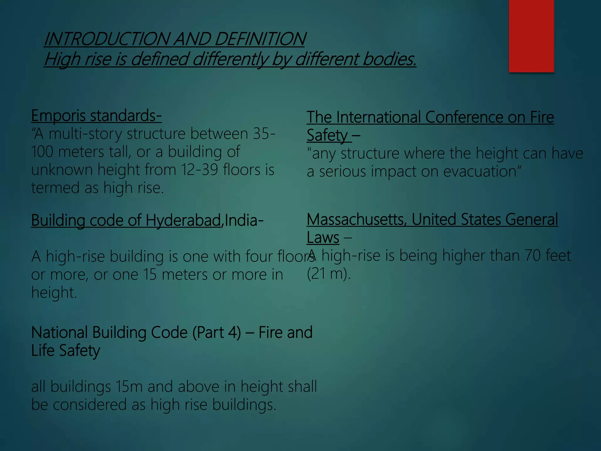
1) High rise buildings are becoming more common due to scarcity of land and demand for space. They are defined differently but generally refer to buildings over 15 meters tall.
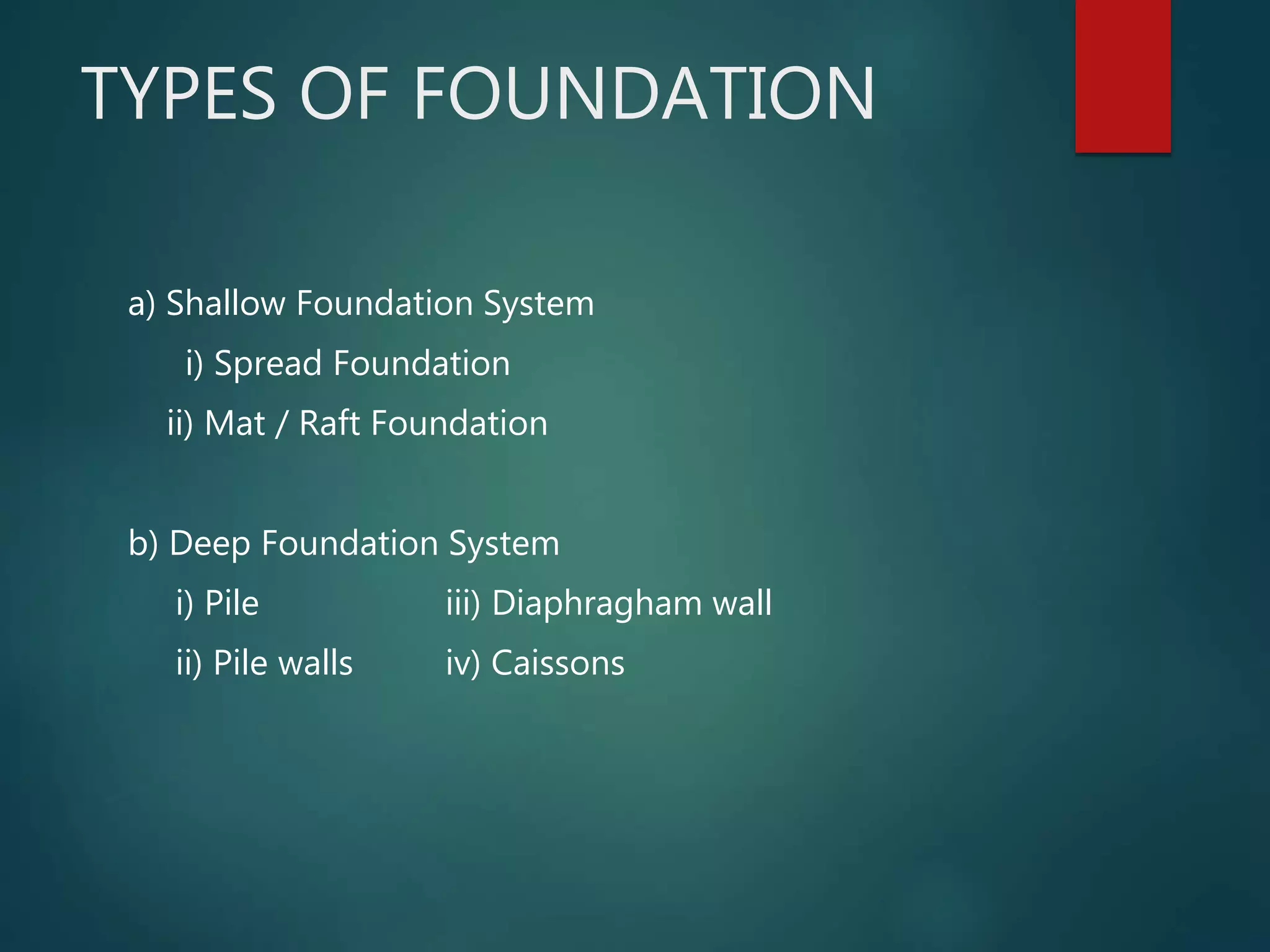
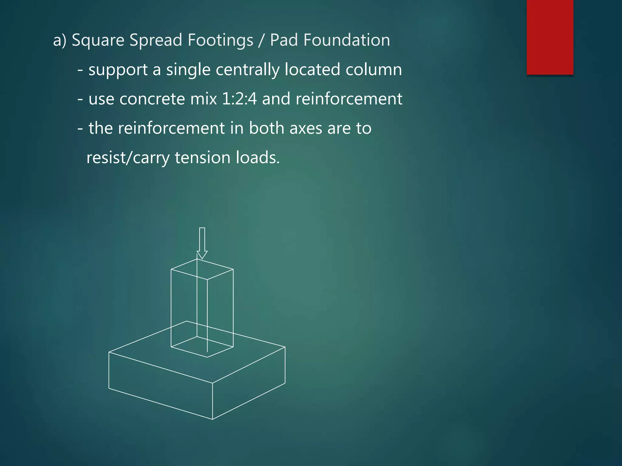
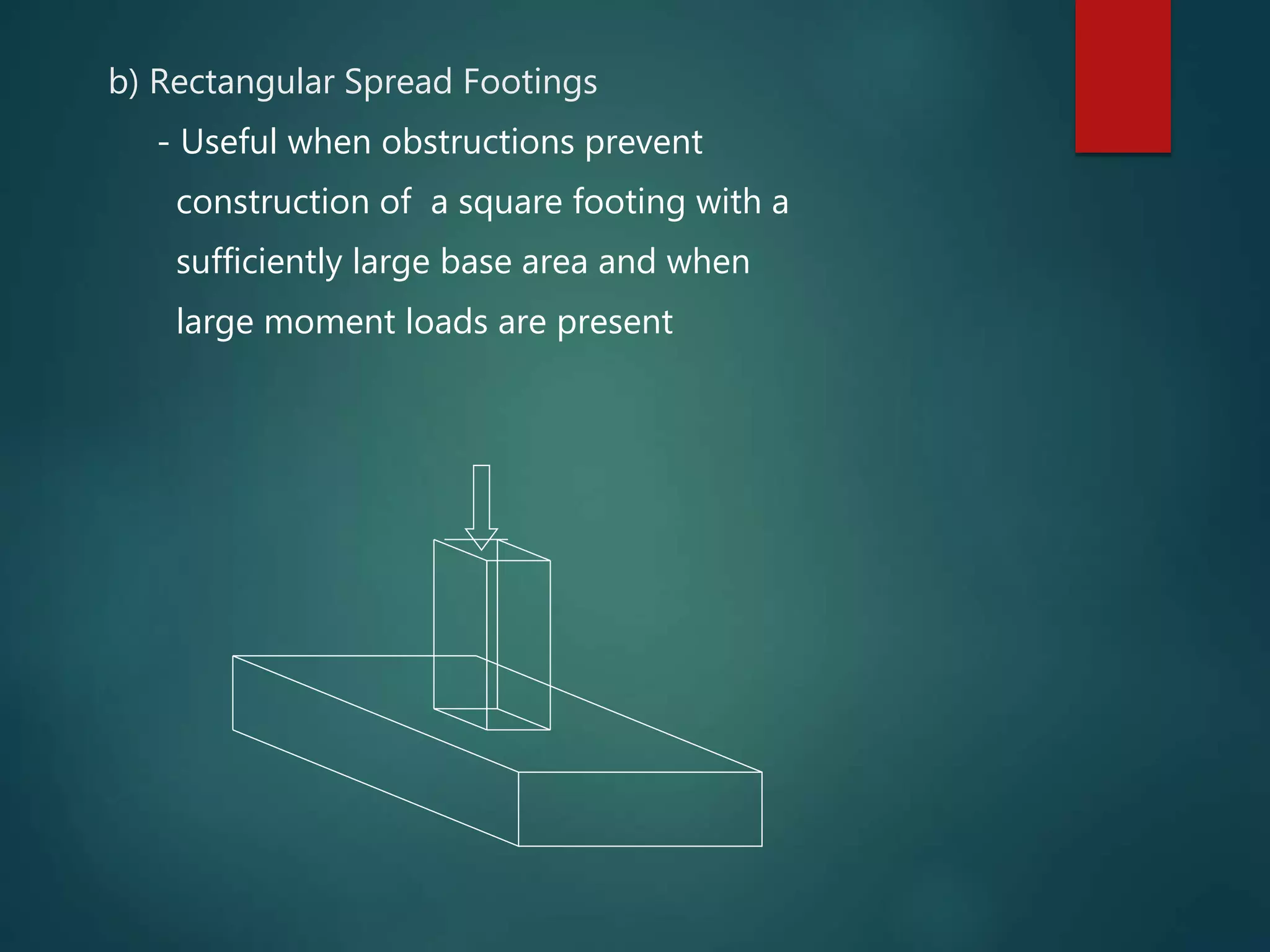
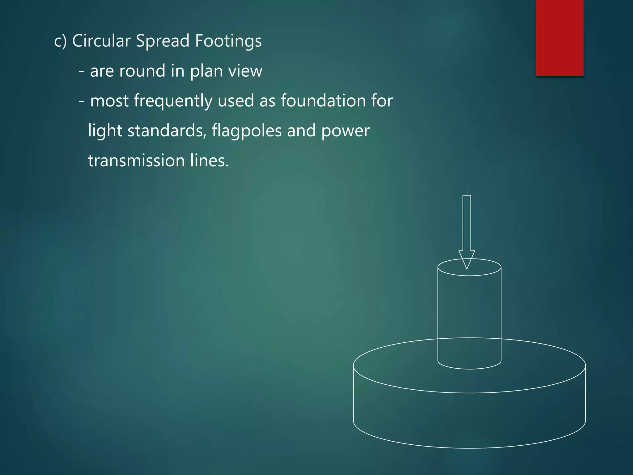
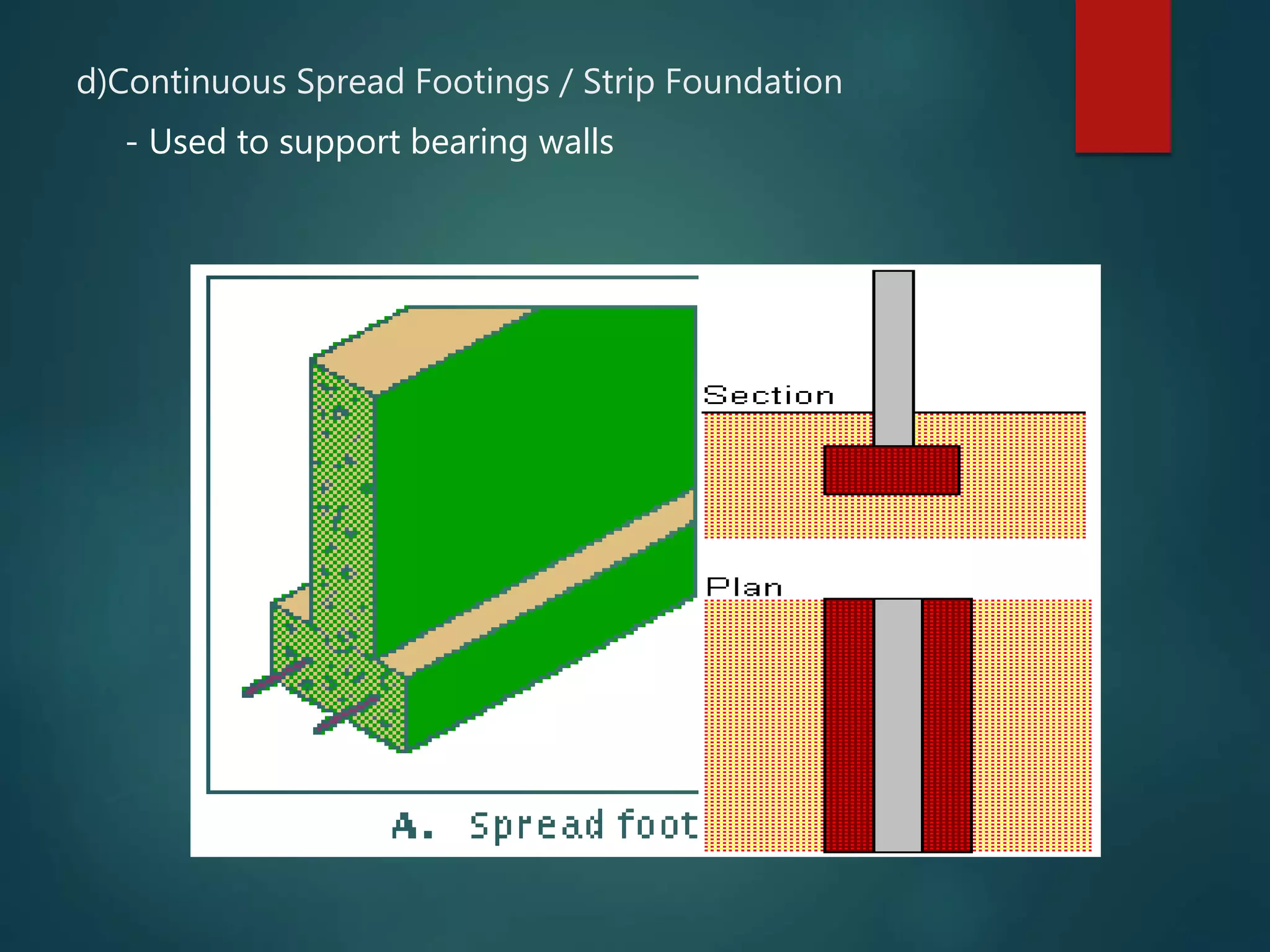
2) Foundations for high rise buildings include shallow foundations like spread footings and mat foundations, and deep foundations like piles. Piles transfer load through end bearing or friction along their length.
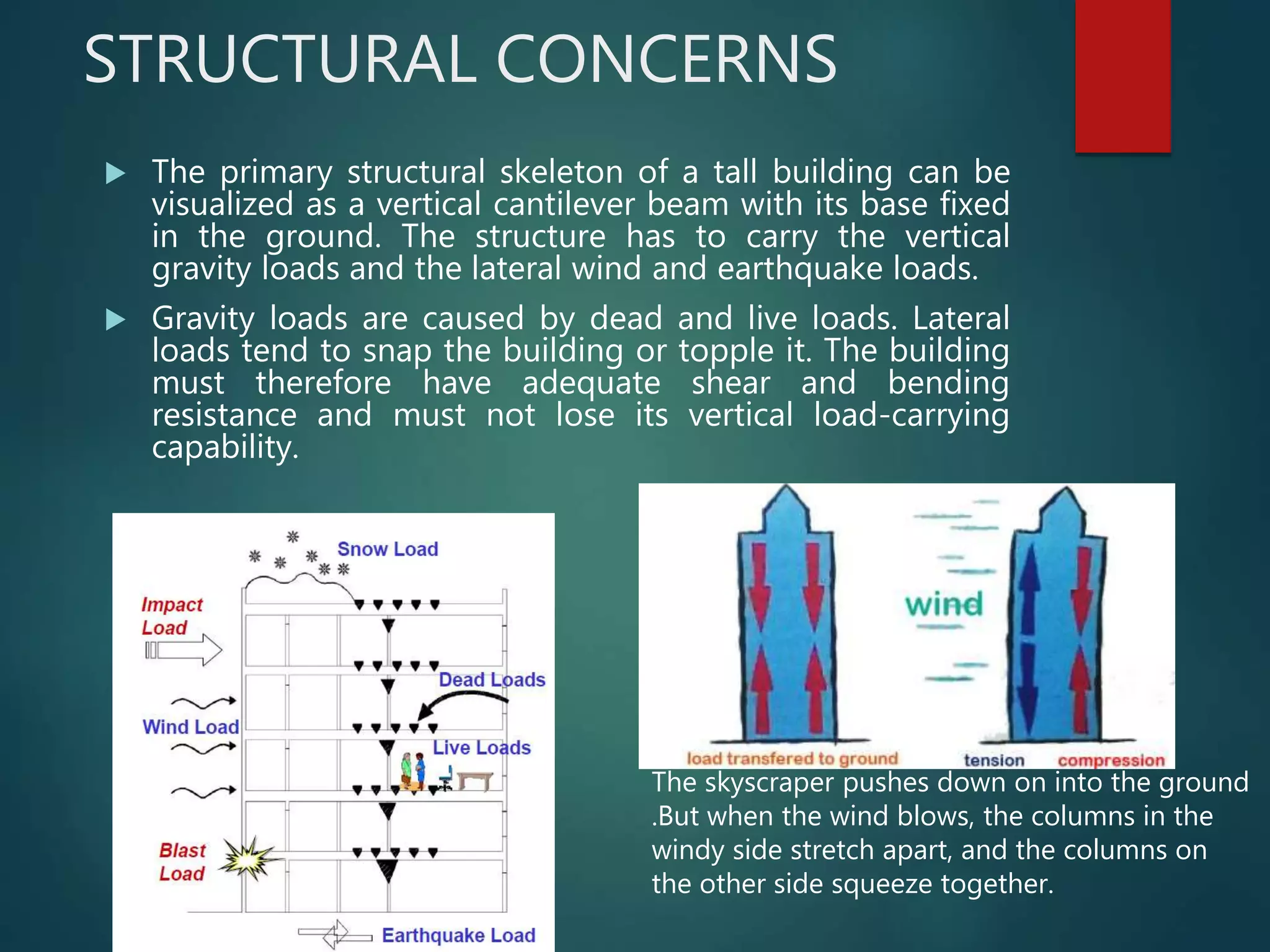
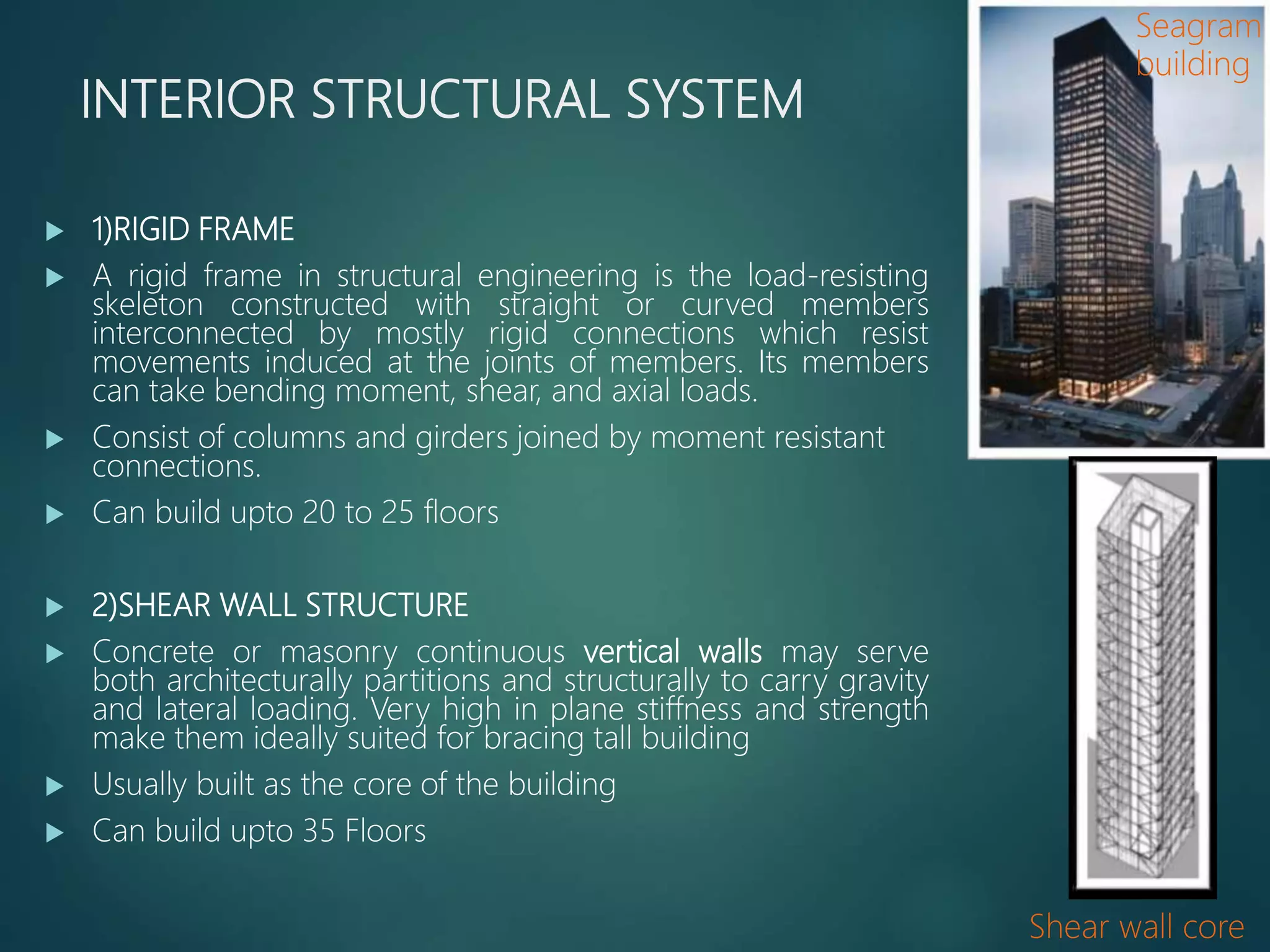
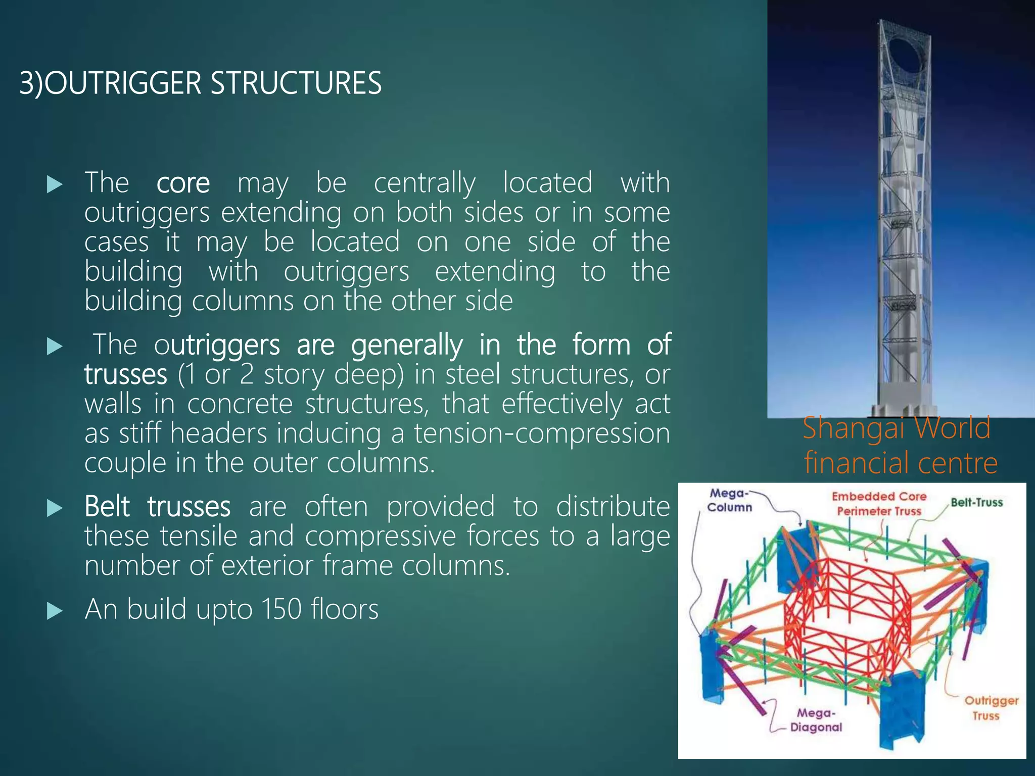
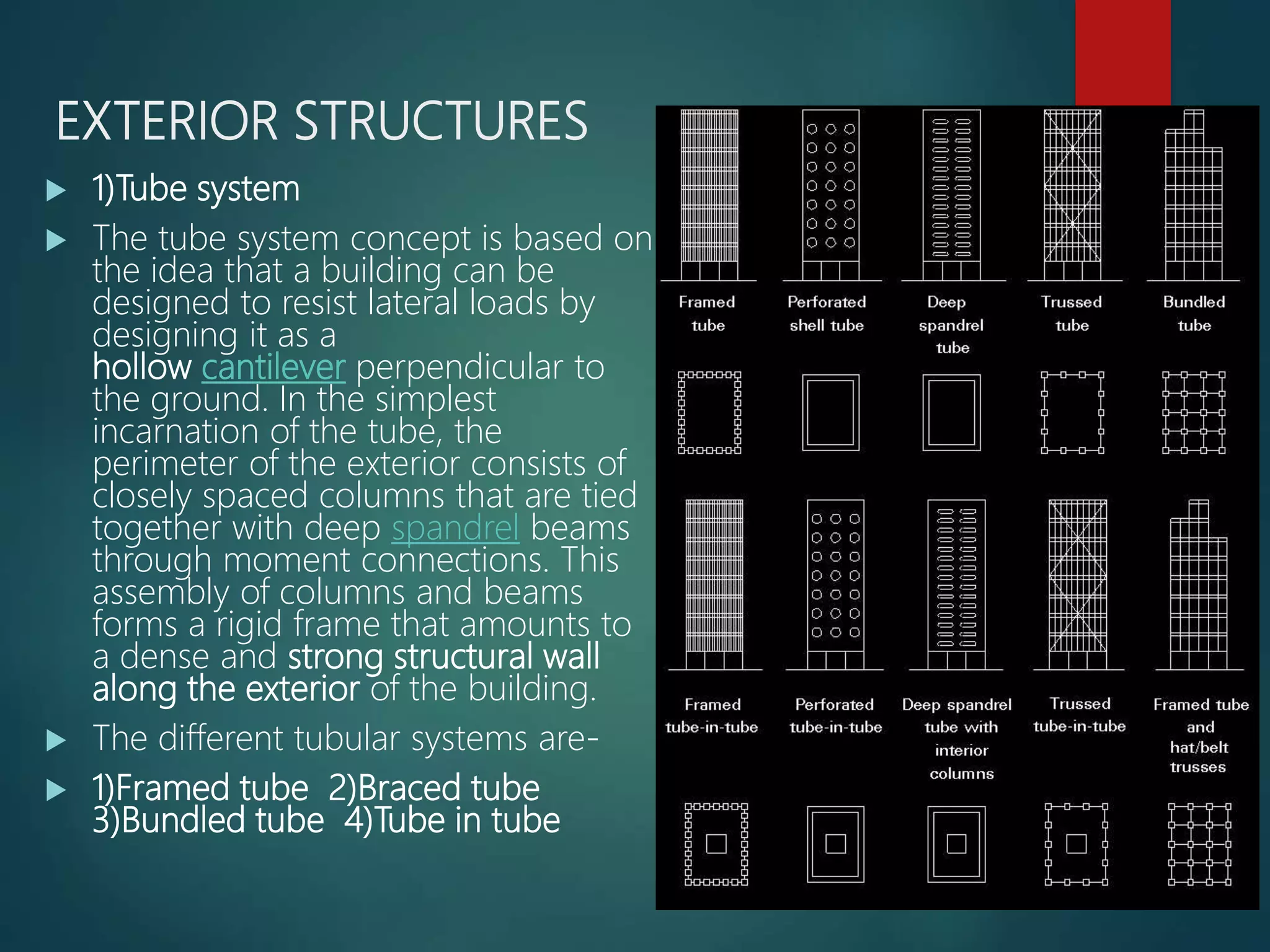
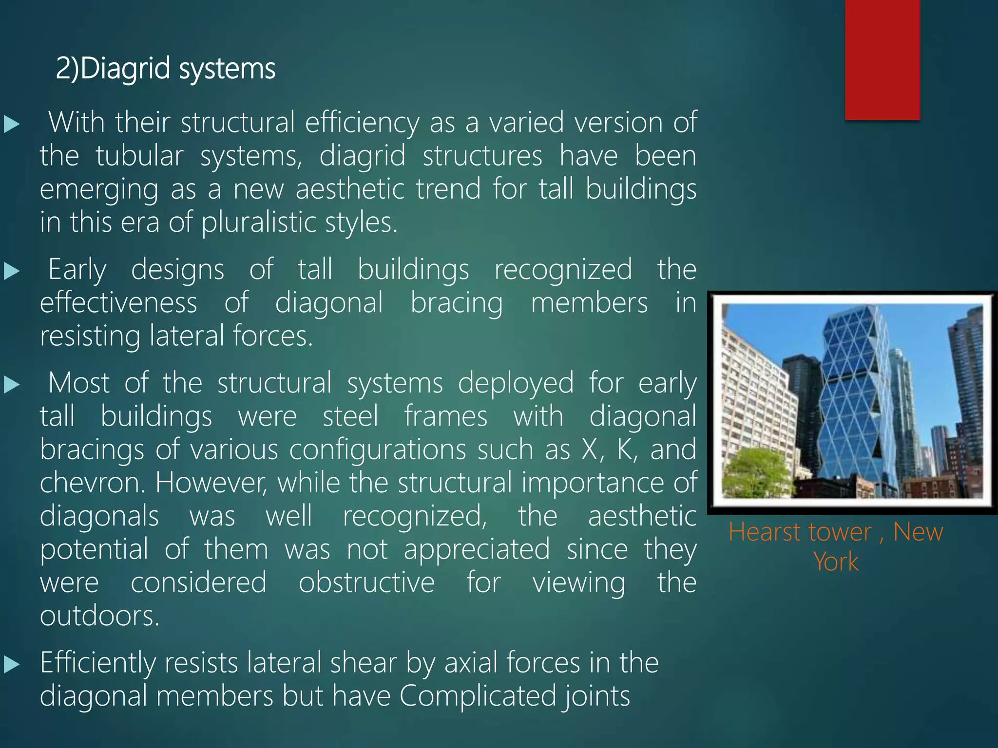
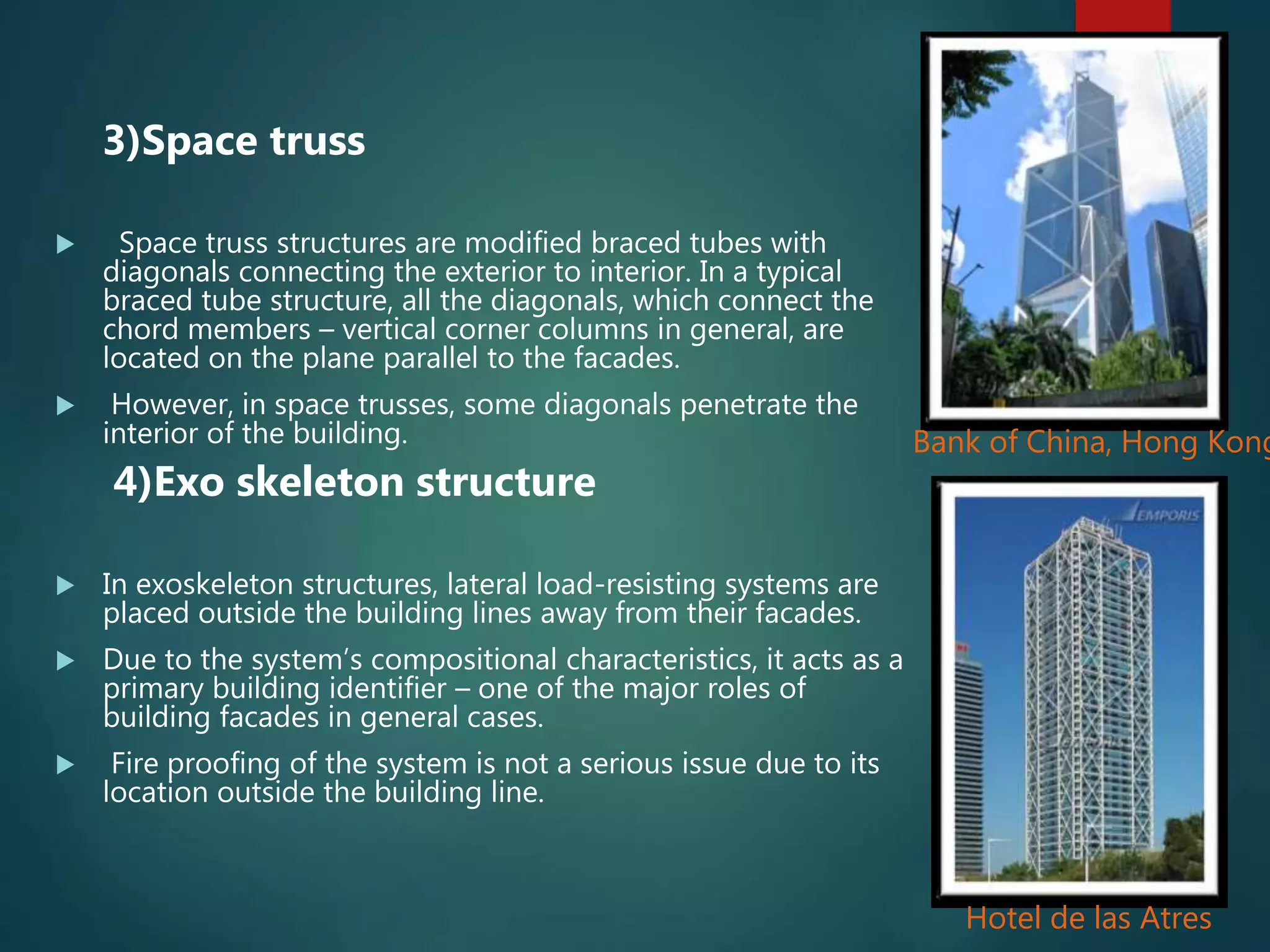
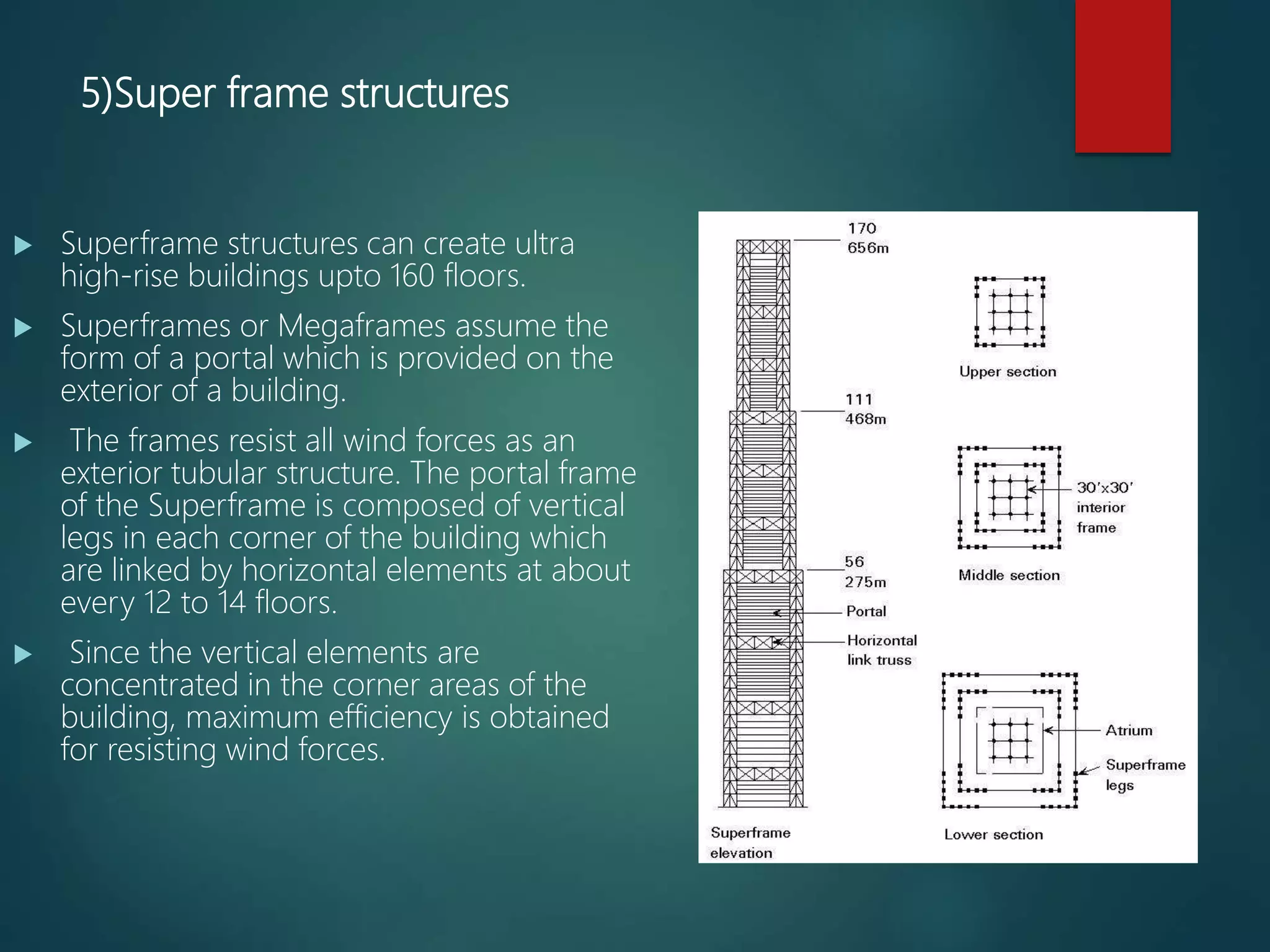
3) Structural systems for high rise buildings must resist both gravity and lateral loads. Interior systems include rigid frames and shear walls. Exterior systems such as tube and diagrid systems resist loads along the building perimeter.