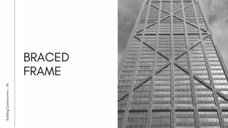
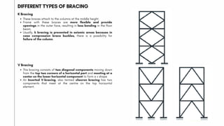
4. WHAT IS A SHEAR WALL?
Shear walls are also called structural walls.
Shear wall is a vertical element used to resist lateral
forces such as wind and seismic forces acting on a building
structure.
It works as a vertical cantilever beam supported at the
ground carrying vertical load together with columns.
They are mainly used in tall buildings.
They can be interior or exterior walls.
They generally start at the foundation and run the full
height of the building.
5. FUNCTIONS OF SHEAR WALLS
Resist Lateral loads, Seismic loads, Vertical Forces (gravity)
Reduces lateral sway of the building
Provide large strength and stiffness to buildings in the direction
of their orientation
The rigid vertical diaphragm transfers the loads into
Foundations
Well-distributed reinforcements
Minimize damages to structural and Nonstructural elements
6. ADVANTAGES OF SHEAR WALLS
Thinner walls
Light weight
Fast construction time
Fast performance
Enough well distributed reinforcements
Cost effectiveness
Minimized damages to structural and Non structural elements.
ADVANTAGES
7. LOCATION OF THE SHEAR WALL
The location of the shear wall depends on the;
Structure plan.
1.
Core location.
2.
Building symmetry.
3.
The lateral force of the structure.
4.
Unsymmetric location is not desirable Symmetric location is desirable
The shear wall must be located in such a way that, there is a maximum probability of lateral load is predicted to apply along the plane of the shear
wall.
8. TYPES OF THE SHEAR WALL
Reinforced concrete shear wall
1) On the basis of the material used for construction
The concrete shear wall is the most effective wall used in order to increase the stiffness and decrease the lateral movement due to shear and lateral forces.
Steel-sheet shear wall
They do not break thus entire shear resistance is governed by ductile behavior and flexural strength. These walls can act as plate girders along with the analogy of
columns as flanges, the wall sheet(plate) as the web, and the beam as stiffeners.
Wooden shear wall
They contain the vertical and horizontal struts for compression and tension forces attached at the back of the ply or planks. Sometimes even bracings (diagonal
supports) are provided to increase the stiffness and decrease the shear action.
Hollow concrete blocks
They are economical methods to construct the shear wall and used instead of the RCC shear wall. But their structural performance is comparatively less than the RC
shear wall.
9. COUPLED SHEAR WALL
Coupled Shear Wall When two shear walls are
interconnected by beams through their height then the
shear wall
A coupled shear wall is part of a shear wall system, made of
coupling beams and wall piers.
It provides more openings, which increase the
functional flexibility in architecture.
Coupled shear walls are one of the systems commonly used
in medium and high rise structures to resist lateral forces.
12. A simplified drawing of an infilled frame structure showing floor slabs supported by beams
A framework of beams and columns in which some bays of frames are infilled with masonry walls that may or may not be mechanically
connected to the frame. Due to great stiffness and strength in their planes, infill walls do not allow the beams and columns to bend under
horizontal loading, changing the structural performance of the frame.
STRUCTURAL SYSTEM
13. Diagonal Strut Model for infill frames
During an earthquake, diagonal compression struts form in the infills so the structure behaves more like a Braced Frame rather than a Moment
Frame. Infill walls can be part-height or completely fill the frame.
EARTHQUAKE RESISTANT
14. Additional measures can be taken to improve the behaviour of infilled frames subjected to seismic actions.
The use of tapered beam-columns joints with diagonal reinforcement contributes to a reduction of the distortion of the masonry panel by
limiting the opening of the joints .
This improves the transfer of the lateral forces from the frame to the panel and increases the width of the compressive strut.
CONSTRUCTIONS DETAILS
Reinforcing details for infilled frames Detail of the tapered beam-column joints.
15. Diagonal Strut Model for infill frames
Due to random nature of masonry infill, it is difficult to predict the stiffness and strength of this system.
No method of analyzing infilled frames has gained general acceptance.
LIMITATIONS
16. Reinforced concrete frame with brick masonry infill walls, India
EXAMPLES
Reinforced concrete frame with brick masonry infills under
construction, India
17. Reinforced concrete frame building with concrete block infill
walls, Padang, Indonesia
EXAMPLES
Reinforced concrete frame building with brick infill walls under
construction, Kathmandu, Nepal
18. Reinforced concrete frame building with hollow clay tile infills
in Algiers
EXAMPLES
Reinforced concrete frame infilled with stone masonry panels
in M'Sila
19. Reinforced concrete frame with masonry infills, Tangier,
Morocco
EXAMPLES
Detail of a reinforced concrete frame with hollow clay tile
infill, Rabbat, Morocco
20. SUMMARY
Infilled frame structure system consists of beam and column
framework that some of the bays infilled with masonry,
reinforced concrete, or block walls.
Infill walls can be part-height or completely fill the frame.
The walls may or may not be connected to the formwork.
Great in plan stiffness and strength of the walls prevent
bending of beams and columns under horizontal loads. As a
result, frame structural performance will be improved.
During an earthquake, diagonal compression struts form in
the infills so the structure behaves more like a Braced Frame
rather than a Moment Frame.
It can build up to 30 storey buildings.
INFILL WALL STRUCTURE SYSTEM
22. A braced frame is a very strong structural
system that is commonly used in structures
subject to lateral loads such as wind and
seismic pressure.
The members in a braced frame are generally
made of structural steel, which can work
effectively both in tension and compression.
The beams and columns that form the frame
carry vertical loads, and the bracing system
carries the lateral loads.
WHAT ARE BRACED FRAME ?
23. Horizontal bracing system
Vertical bracing system
TYPES OF BRACING SYSTEM
Horizontal bracing system
The horizontal bracing system includes bracing at each floor in a horizontal plane offers load paths for the lateral forces to transfer
them to vertical bracing planes.
It is essential at each floor level. Still, the floor system may provide sufficient resistance, but roofs may demand bracing.
This bracing system aims to transmit lateral loads from columns at the structure's perimeter to the vertical bracing planes.
The pressure of wind forces on the structure's cladding generates horizontal forces on columns at the edge.
Vertical bracing system
A vertical bracing system is used in a vertical plane in the middle of column lines that offers load paths for moving lateral loads to the
ground level.
This system gives lateral stability by transmitting horizontal loads to the foundations and resists the structure's overall sway.
Vertical bracings are positioned between lines of two columns.
24. Types of bracing
Single diagonals
Cross-bracing
V-bracing
K-bracing
DIFFERENT TYPES OF BRACING
Single diagonals
In this bracing, triangulation is created by placing diagonal
structural components into rectangular areas of a structural
frame to stabilize the structure.
It is planned to withstand both compression and tension
forces.
If the inclination of the bracing component is less than 45° from
vertical, then structure sway sensitivity may increase.
Cross-bracing
Cross-bracing utilizes two diagonal components intersecting
each other and are required to resist tension only.
Depending on the direction of loading, a single brace acts to
oppose sideways forces promptly.
Cross bracing on the outer building front can interrupt the
position and function of openings, resulting in more significant
bending in floor beams.
Thus, tensile components give required lateral stability, and the
floor beams function as a part of the bracing system.
25. CANNON PLACE, LONDON
Location - Greater London, England
Completed year -
Floor Count - Eight floors
HOTEL ARTS , SPAIN
Location - Barcelona, Catalonia, Spain
Completed year - 1994
Architects - Bruce Graham
(Skidmore, Owings & Merrill)
Floor Count - 44 Storeys
154 m
Height -
26. DIFFERENT TYPES OF BRACING
K Bracing
These braces attach to the columns at the middle height.
Frame with these braces are more flexible and provide
openings in the outer face, resulting in less bending in the floor
beam.
Usually, k bracing is prevented in seismic areas because in
case compression brace buckles, there is a possibility for
failure of the column.
V Bracing
This bracing consists of two diagonal components moving down
from the top two corners of a horizontal part and meeting at a
center on the lower horizontal component to form a v shape
An Inverted V-bracing, also termed chevron bracing has two
components that meet at the centre on the top horizontal
element.
27. Bracing helps for retrofitting and strengthening an existing structure.
1.
The bracing system significantly influences the restriction to the relative floor-to-floor lateral displacement.
2.
Bracing System helps to reduce inter-story drift significantly.
3.
Bracing helps to resist wind and seismic force in a more excellent way.
4.
It has the flexibility to design to achieve the demanded strength and stiffness.
5.
A significant advantage of providing bracing is the lowering in lateral displacement.
6.
In this case, concentric (X) bracing performs better than Eccentric (V) bracing.
7.
It is easy to install, engages less space.
8.
ADVANTAGES OF BRACING
It has a restricted span length of 40 feet when reinforced.
1.
Skilled labourers are required for the construction of the braced structure.
2.
DISADVANTAGES OF BRACING