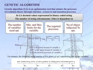
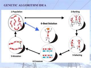
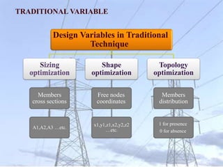
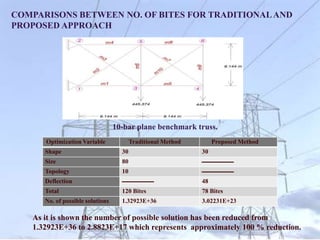
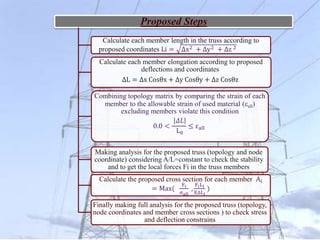
This document summarizes a thesis on using genetic algorithms to optimize space trusses. It begins with background information on the thesis author and supervisors. It then discusses the importance of structural optimization to reduce weight while maintaining safety. The research objectives are outlined as developing a new approach to overcome drawbacks of classical optimization methods by using different design variables. The document provides details on the genetic algorithm approach and compares the proposed method to traditional techniques. Several case studies are presented to demonstrate applying the proposed approach to optimize benchmark space truss problems. Results are compared to other studies to validate the effectiveness of the method.


![Shape, Sizing and Topology optimized 25-bar space truss
structure Model in Matlab .
Size, shape and topology optimized 25-bar space
truss literature results
Members and its groups
Wu [48] Wenyan [22] H. Rahami [23]
This study
1995 2005 2008
Cross section area (in2)
1,2 Group 1 0.1 Removed Removed Removed
2,6
Group 2
0.2 0.10 0.10 0.10
1,5 0.2 0.10 0.10 0.10
2,3 0.2 0.10 0.10 0.10
1,4 0.2 0.10 0.10 Removed
1,6
Group 3
1.1 0.90 0.90 0.90
1,3 1.1 0.90 0.90 0.90
2,5 1.1 0.90 0.90 0.90
2,4 1.1 0.90 0.90 0.90
6,5
Group 4
0.2 Removed Removed Removed
3,4 0.2 Removed Removed Removed
5,4
Group 5
0.3 Removed Removed Removed
6,3 0.3 Removed Removed Removed
4,9
Group 6
0.10 0.10 0.10 0.10
5,8 0.10 0.10 0.10 0.10
6,7 0.10 0.10 0.10 0.10
3,10 0.10 0.10 0.10 0.10
6,9
Group 7
0.2 0.10 0.10 0.10
5,10 0.2 0.10 0.10 0.10
4,7 0.2 0.10 0.10 0.10
3,8 0.2 0.10 0.10 0.10
5,9
Group 8
0.90 1.00 1.00 1.00
6,10 0.90 1.00 1.00 1.00
4,8 0.90 1.00 1.00 1.00
3,7 0.90 1.00 1.00 1.00
X4 41.07 39.91 38.7913 40.60
Y4 53.47 61.99 66.111 58.40
Z4 124.6 118.23 112.9787 123.80
X8 50.8 53.13 48.7924 56.20
Y8 131.48 138.49 138.891 139.20
Weight (lb.) 136.2 114.74 114.3701 114.171
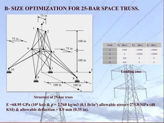
C- SIZE, SHAPE AND TOPOLOGY OPTIMIZATION FOR 25-BAR SPACE TRUSS.
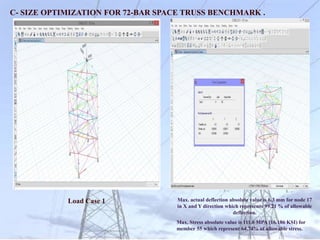
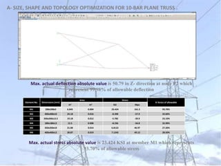
Max. actual deflection absolute value is 8.8889 mm at node
1 in Y direction which represents 99.87% of allowable
deflection.
Max. actual stress absolute value is 119.62 MPA (17.35 KSI)
in member 2,5 which represents 43.73% of allowable stress .
Node 3,4,5& 6 are free in X,Y & Z Dir.
Node 7,8,9&10 are free in X& Y Dir.](https://image.slidesharecdn.com/masterpresentaion-230514105438-4afd55e5/85/Structural-optimization-pptx-20-320.jpg)