Downloaded 459 times


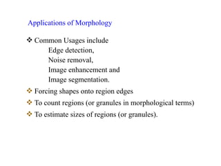
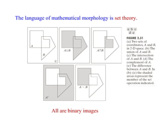
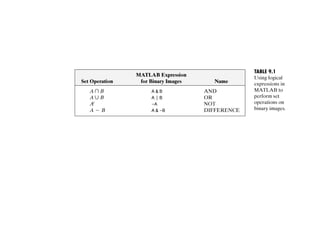
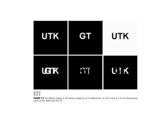
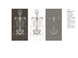
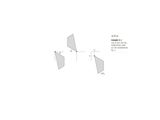
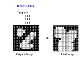
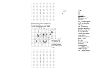
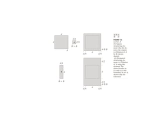
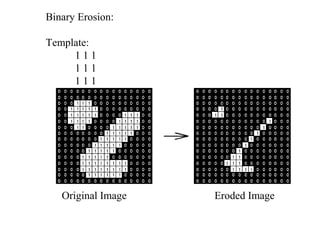
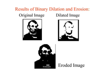
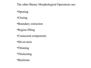
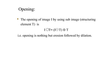
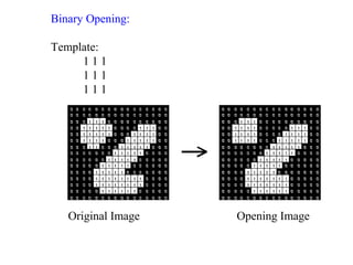
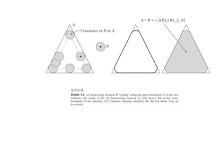
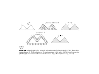


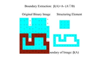
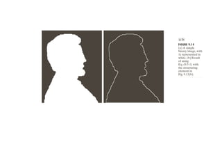
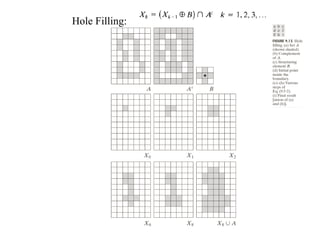
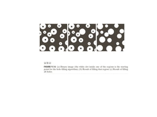
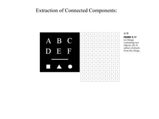
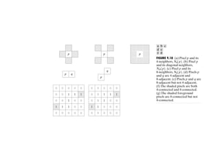
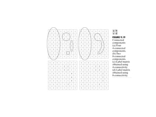
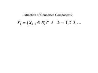
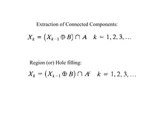
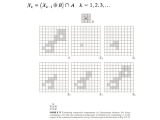
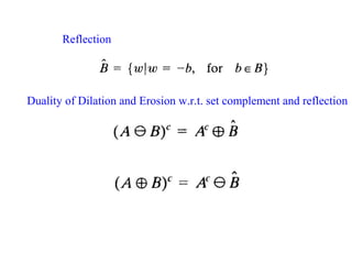
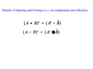
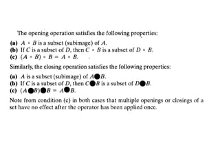
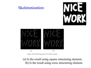
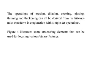
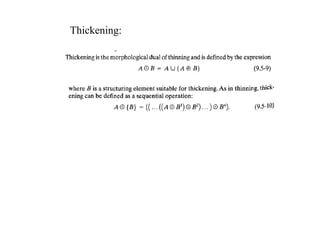

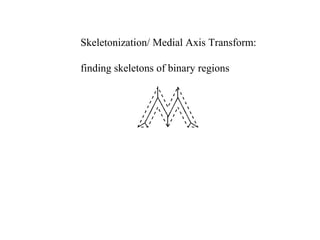
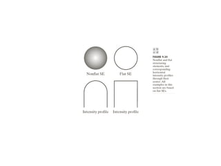
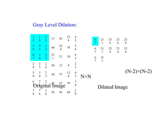
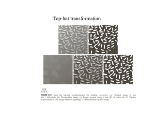
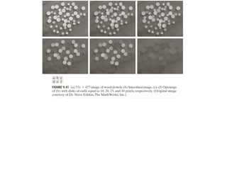
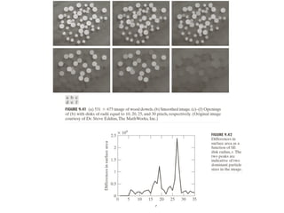
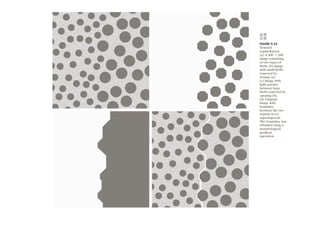
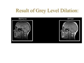
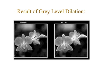
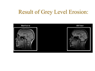
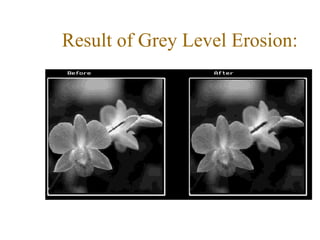

The document discusses various morphological image processing techniques including binary morphology, grayscale morphology, dilation, erosion, opening, closing, boundary extraction, region filling, connected components, hit-or-miss, thinning, thickening, and skeletonization. Morphological operations can be used for tasks like edge detection, noise removal, image enhancement, and image segmentation. The key morphological operations of dilation and erosion expand and shrink binary images using a structuring element, while opening and closing combine these operations to remove noise or fill holes.