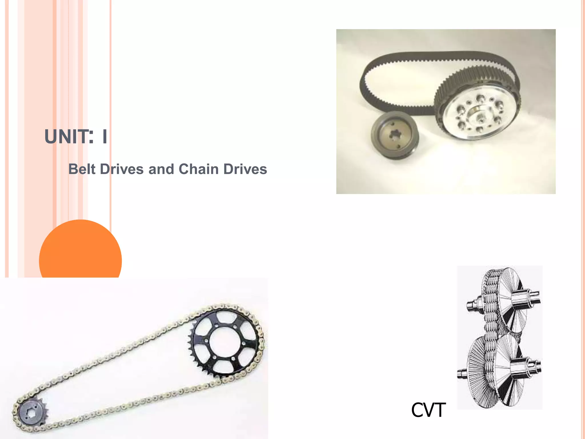
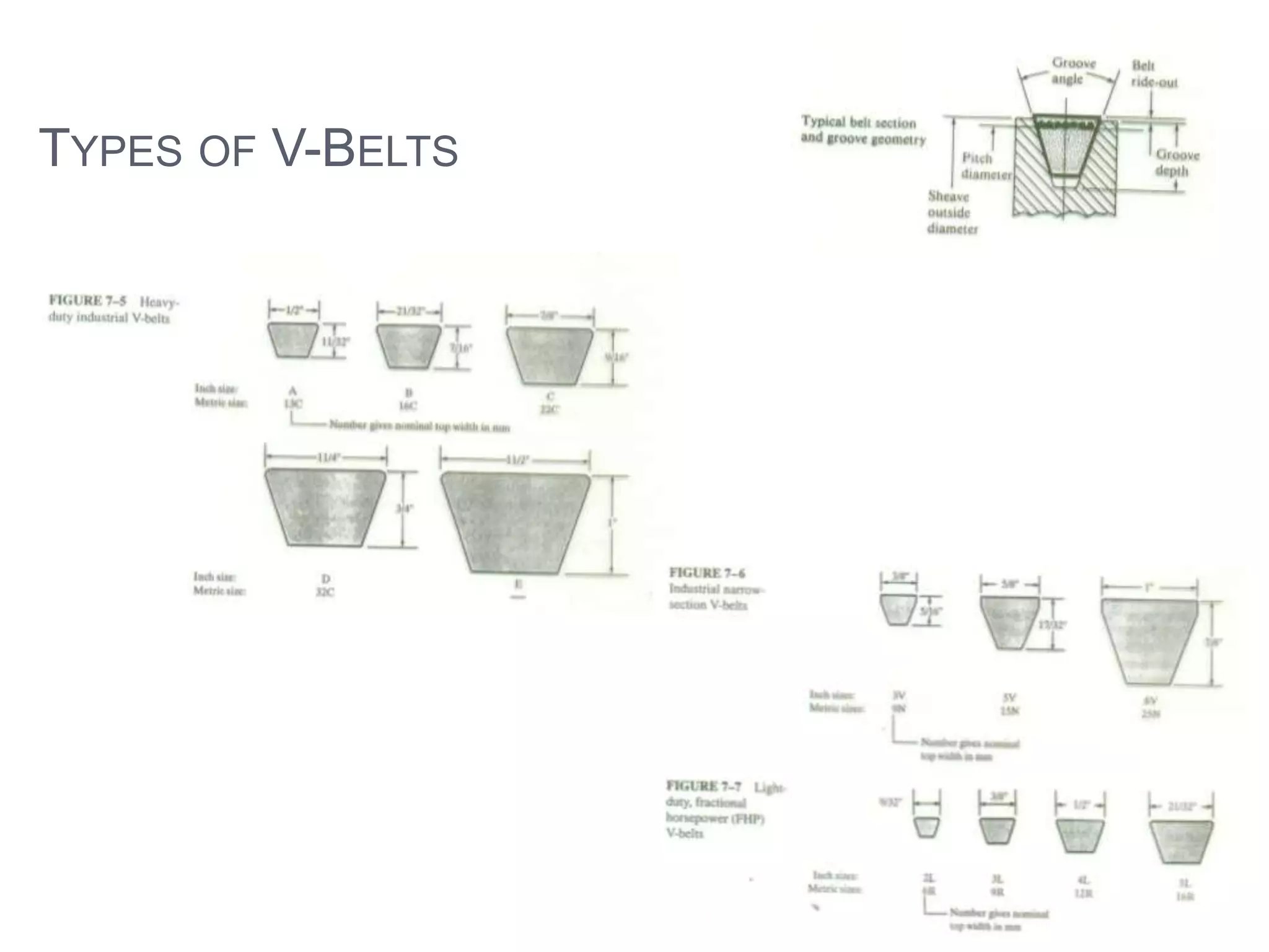
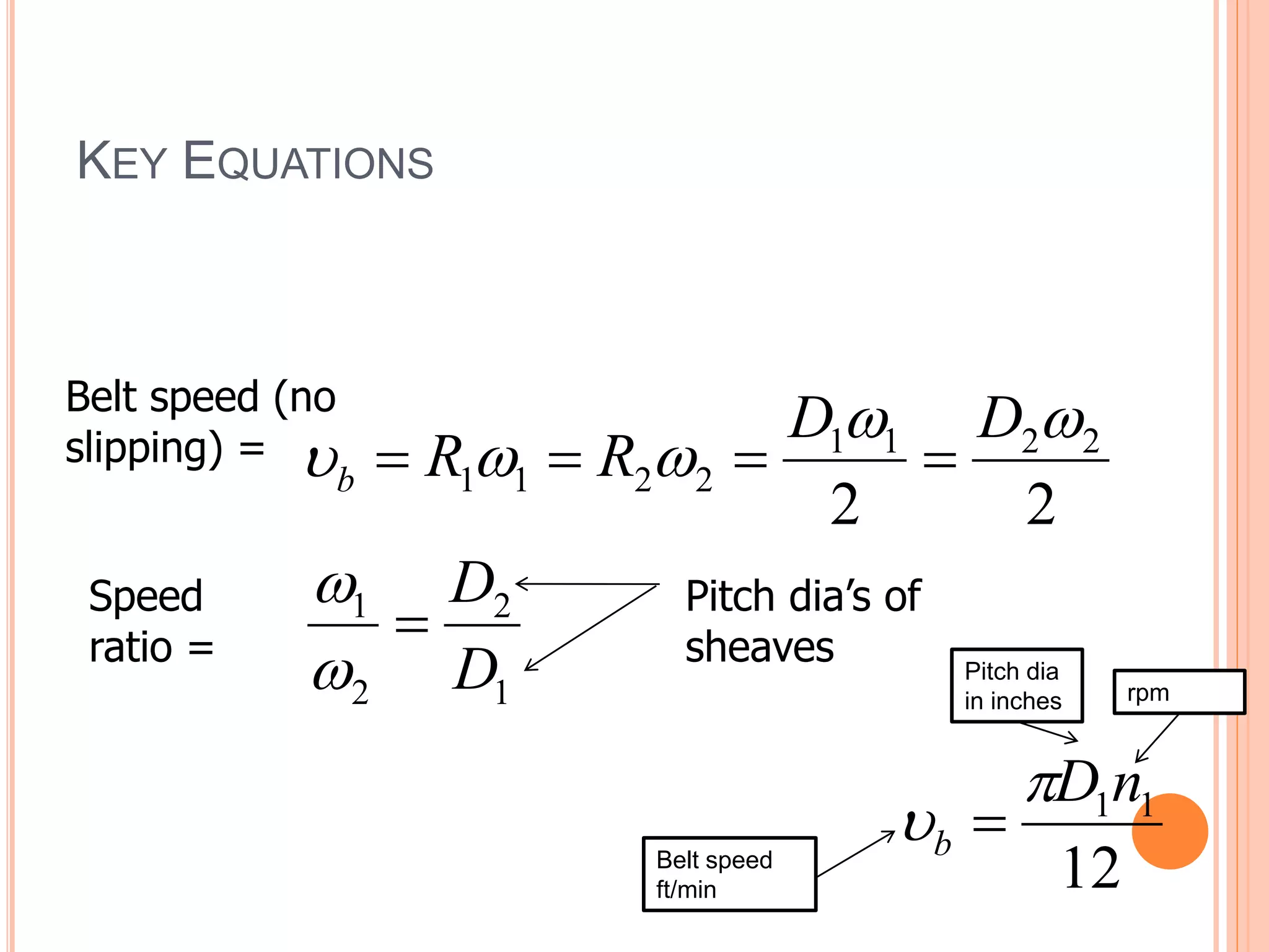
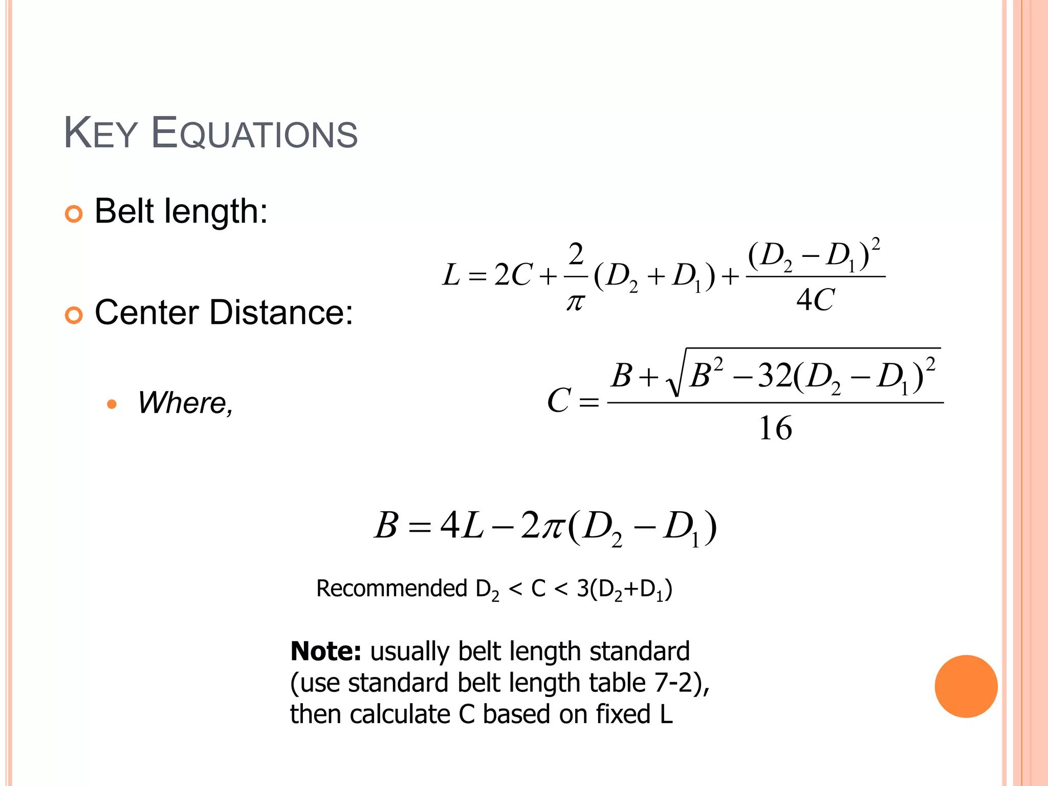
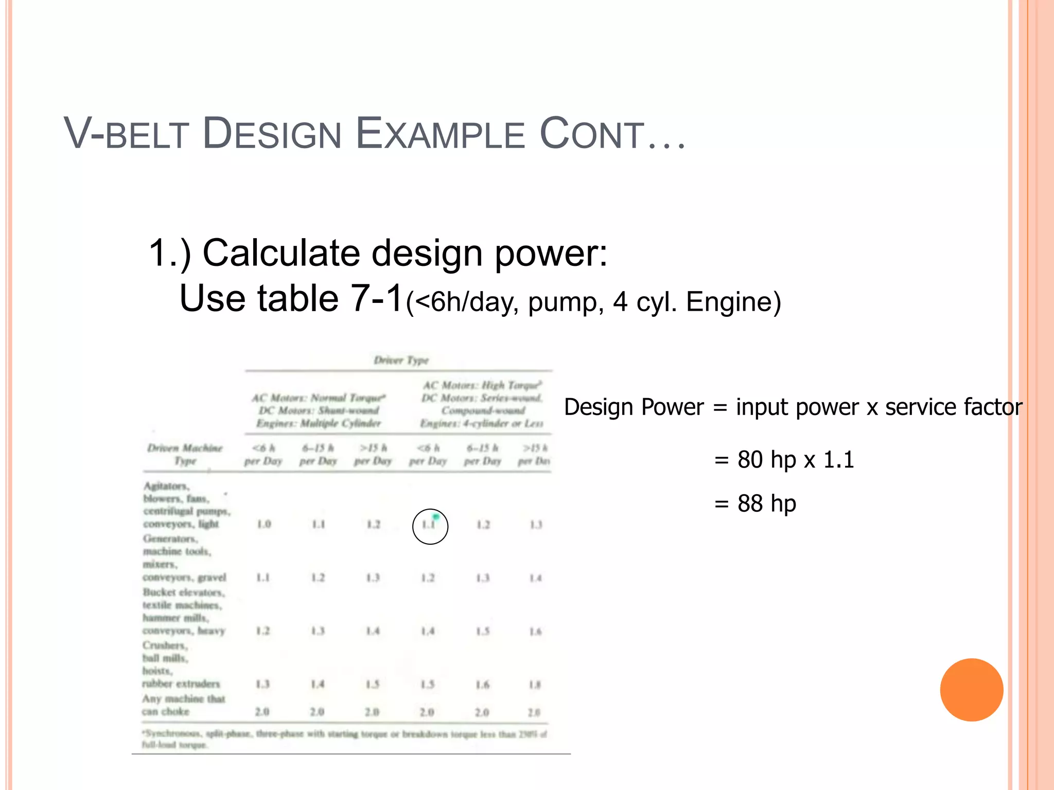
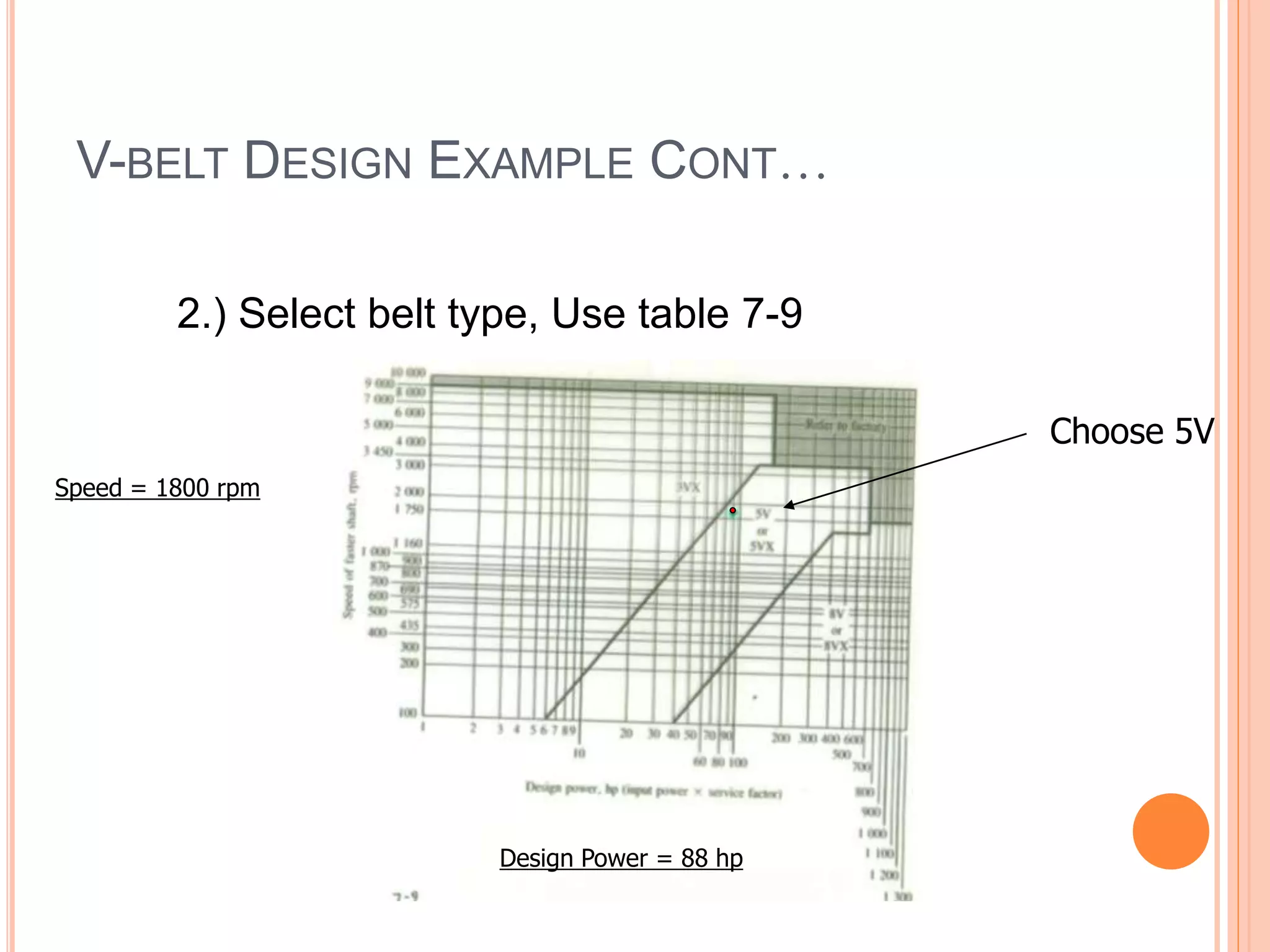
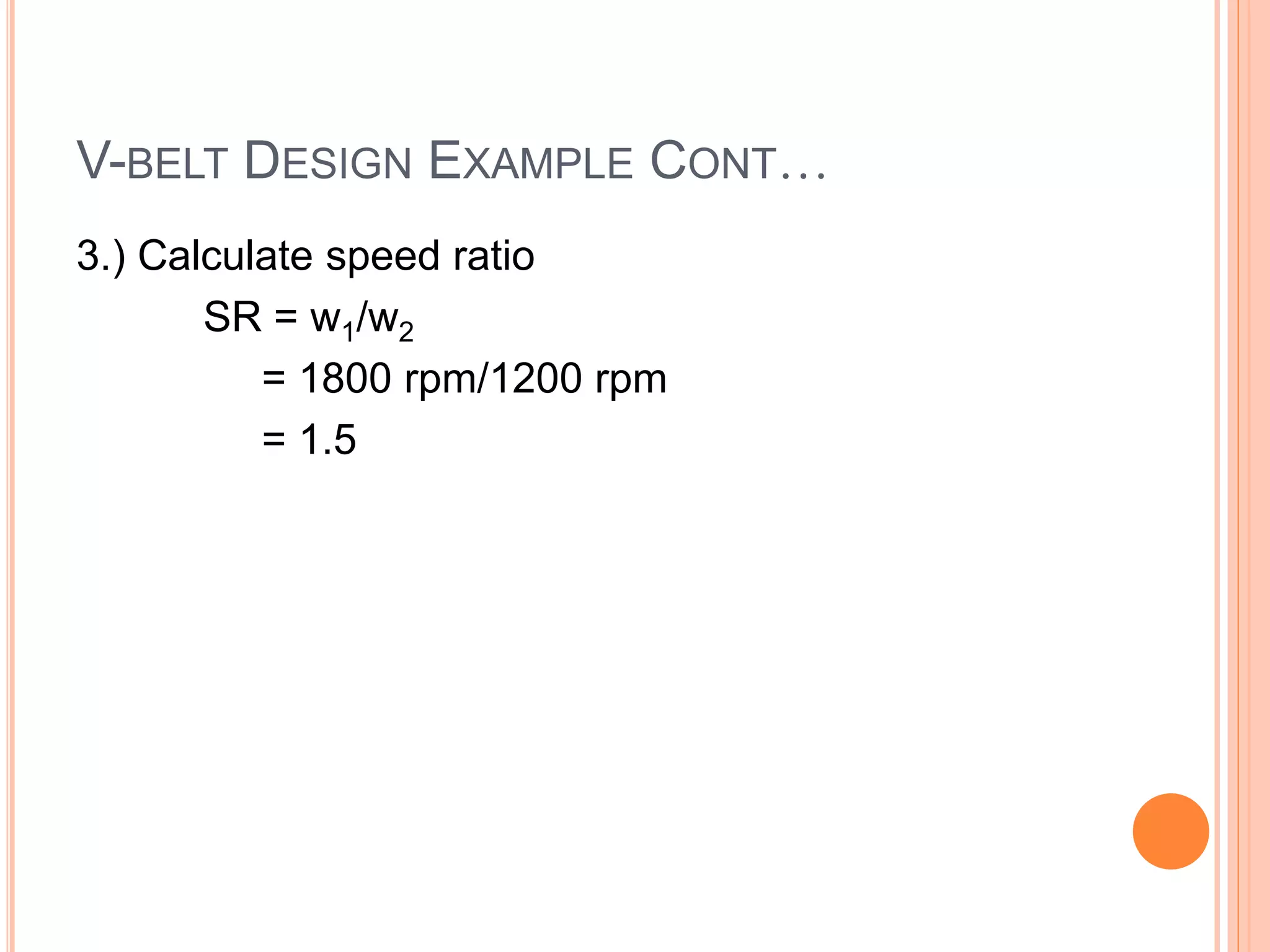
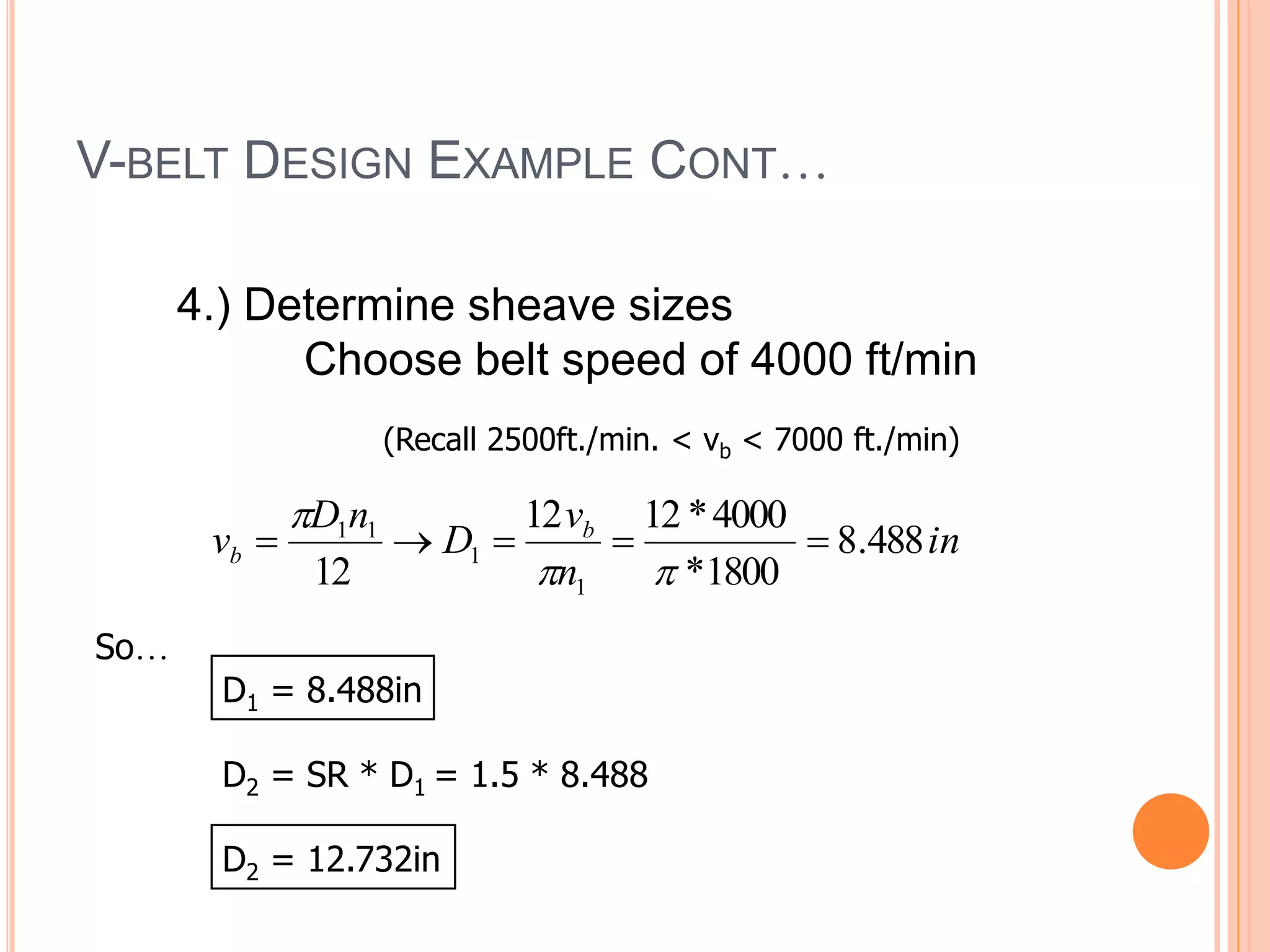
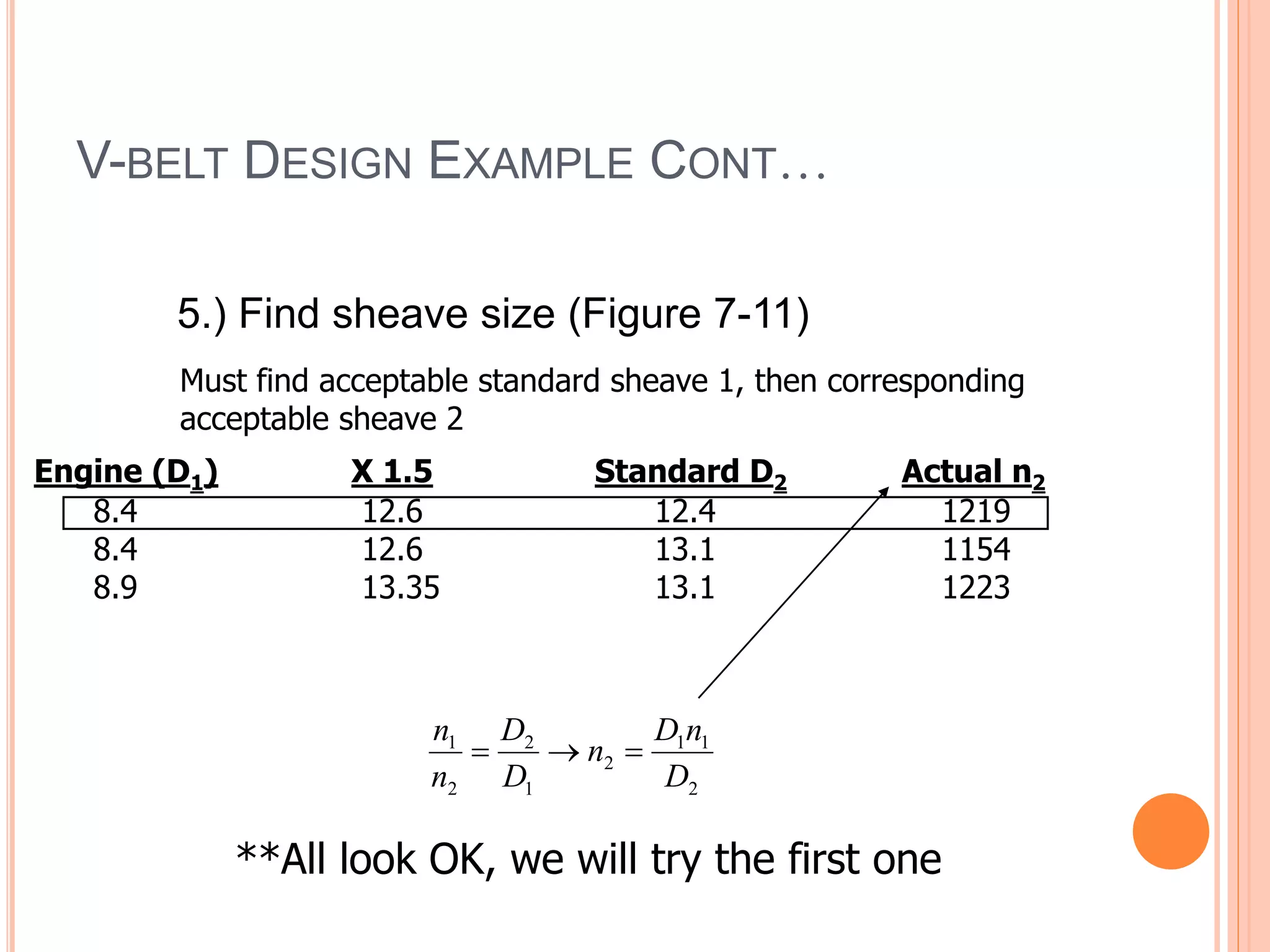
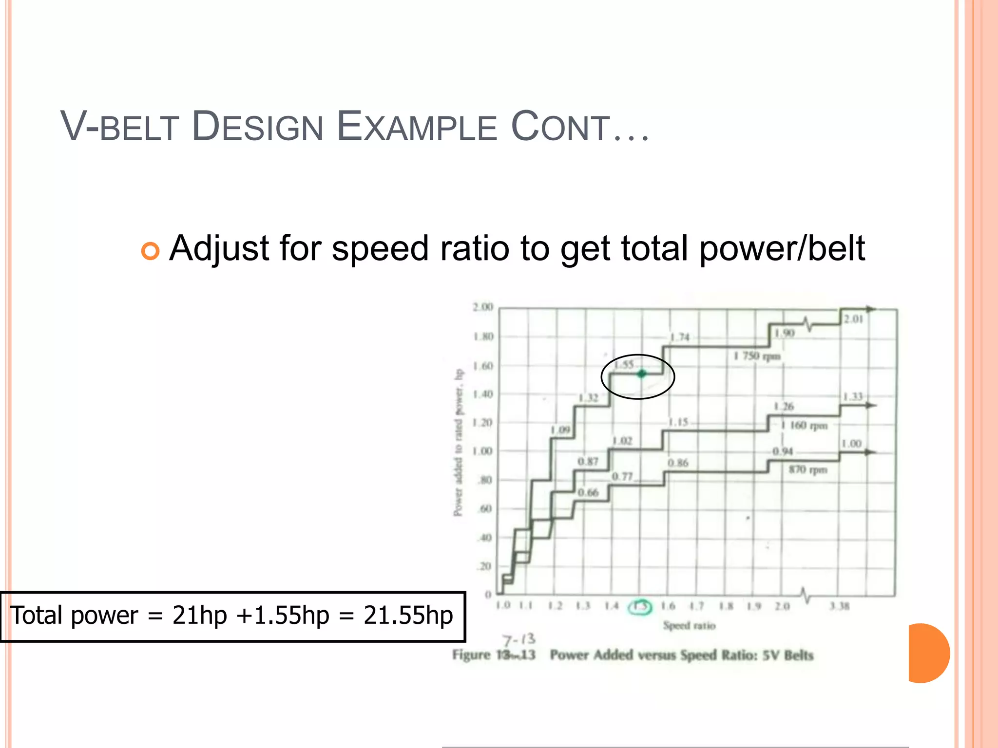
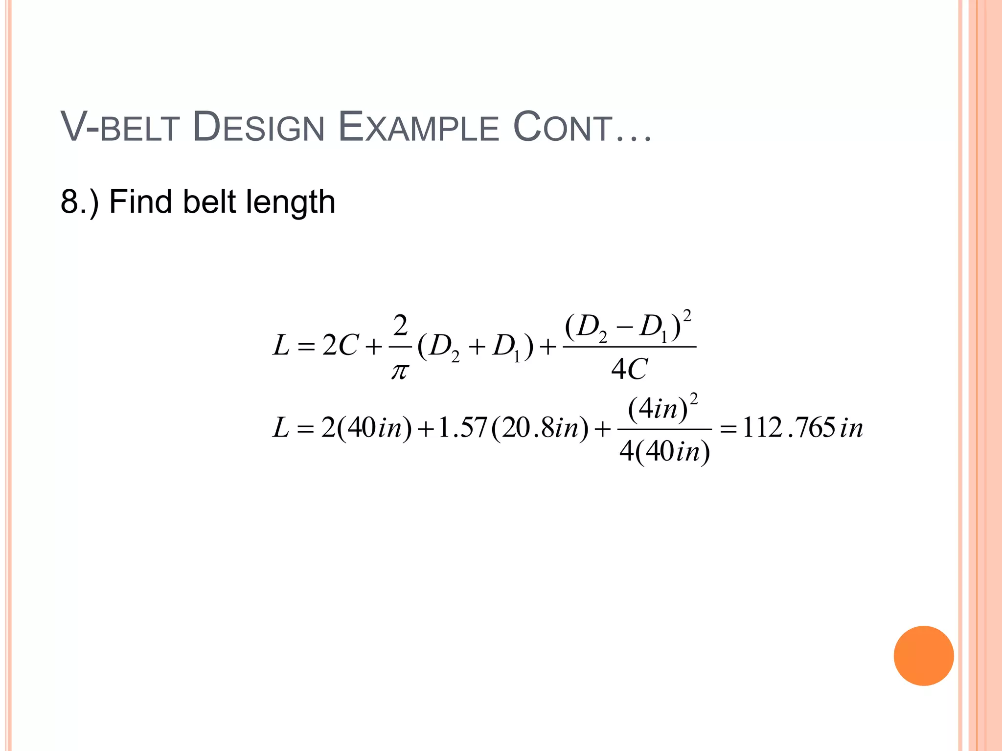
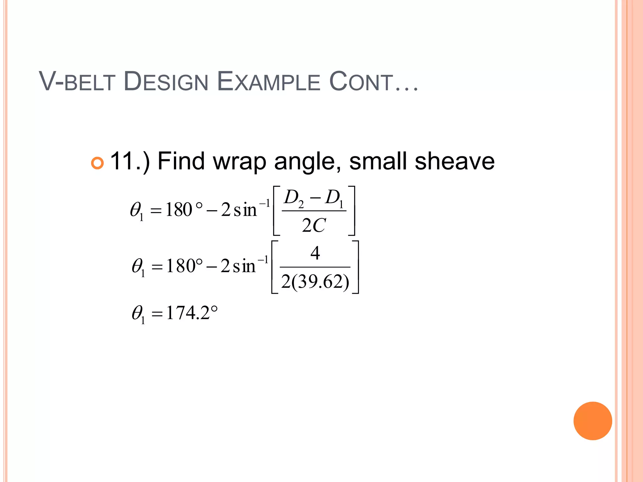
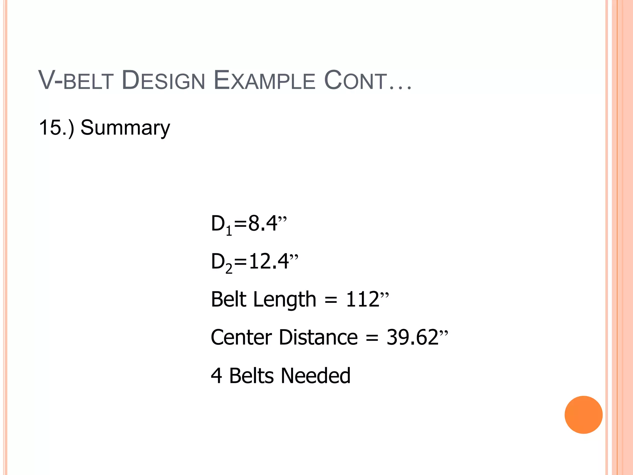
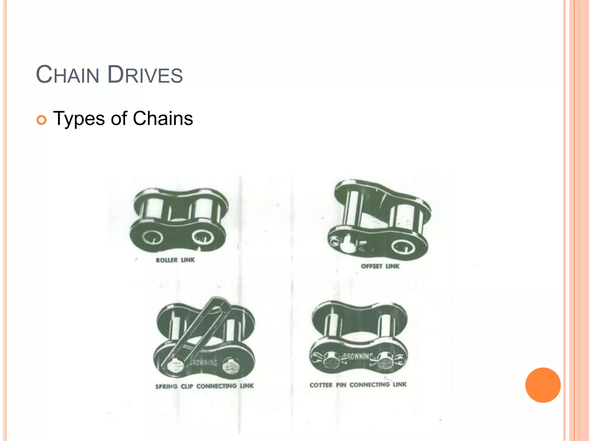
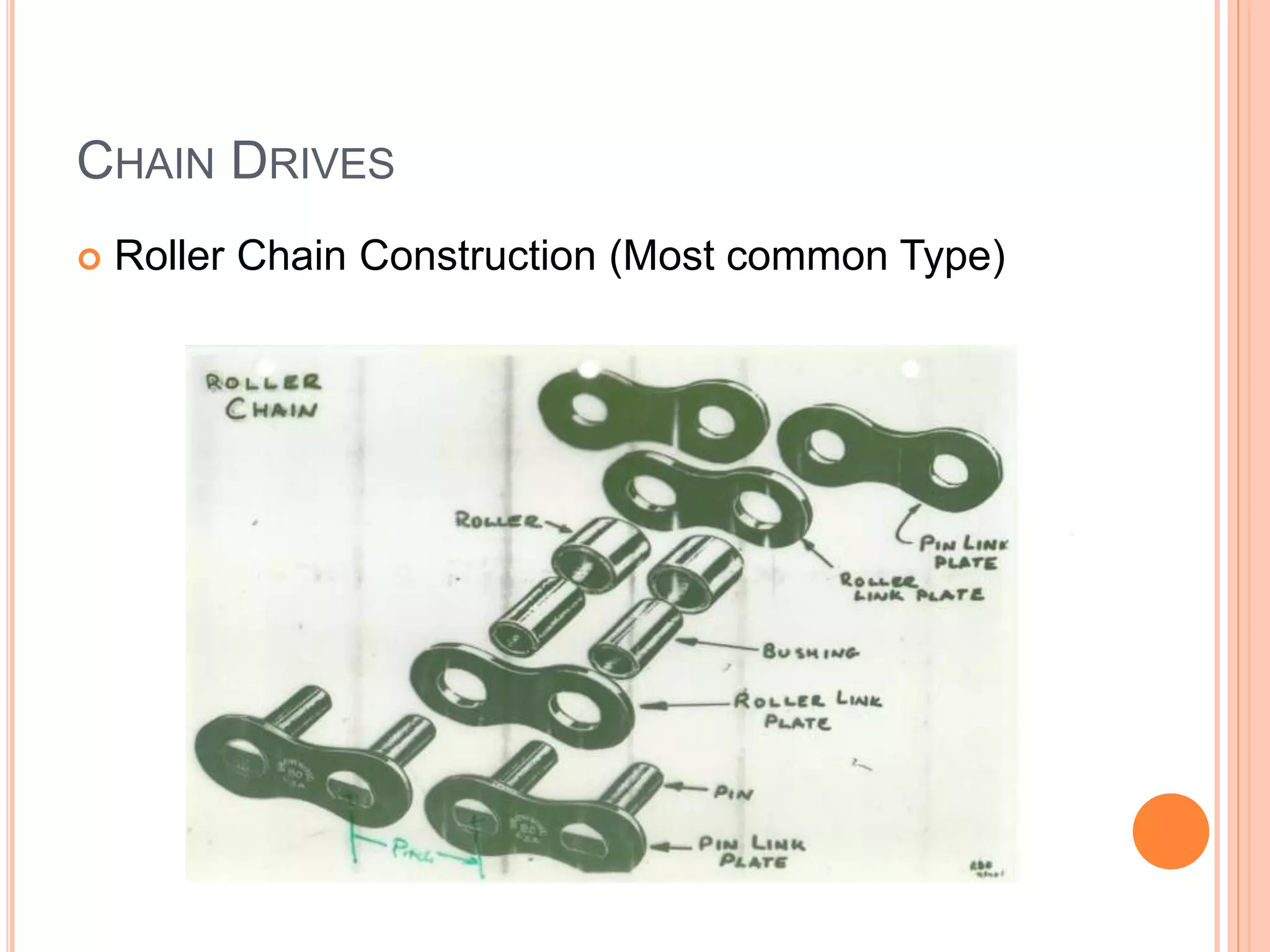
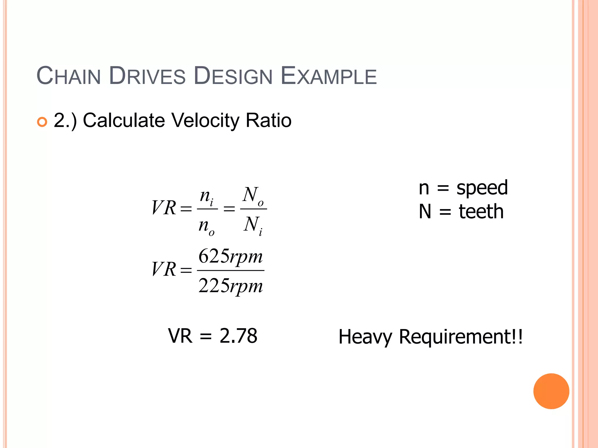
UNIT: I
Belt Drives and Chain Drives
CVT
OVERVIEW – WHY USED?
1.) Transfer power (torque) from one location to
another. From driver: motor,peddles,
engine,windmill,turbine to driven: conveyor belt,
back wheels/bike,generator rock crusher,dryer.
2.) Used to span large distances or need flexible x-
mission elements. Gear drives have a higher
torque capability but not flexible or cheap.
3.) Often used as torque increaser (speed reducer),
max speed ratio: 3.5:1. Gear drives?? Virtually
unlimited!
Applications? Show rust abrader, glove factory, draw sample drive of rust abrader, show slides from mechanism book.
Sometimes
desirable to
have both chain
and belt drive
(Fig 7.1)
Belt: high
speed/low
torque
Chain: Low
speed/high
torque
BELTS VS. CHAINS
Belts
Chains
Use When:
Speed:
Dis:
Advs:
High Speed, Low T High T, Low Speed
2500 < Vt < 7000 ft./min. V < 1500 ft./min.
Must design with standard
lengths, wear, creep,
corrosive environment, slip,
temp., when must have
tension need idler
Must be lubricated,
wear, noise, weight,
vibration
Quiet, flexible, cost Strength, length
flexibility
TYPES OF BELTS:
a)V-belt most common for
machine design, several
types (Fig. 7.5 – 7.8)
•Timing belt (c & d) have
mating pulleys to
minimize slippage
•c) Pos retention due to
mating pulleys
•d) Pos retention due to
increased contact area
•Flat belt
(rubber/leather) not
shown, run on tapered
pulleys
Add notes
TYPES OF V-BELTS
V-BELT DRIVE DESIGN PROCESS
 Need rated power of the driving motor/prime mover. BASE sizing
on this.
 Service factor based on type of driver and driven load.
 Center distance (adjustment for center distance must be provided or
use idler pulley) nominal range D2 < C < 3(D2 + D1)
 Power rating for one belt as a function of size and speed of the
smaller sheave
 Belt length (then choose standard size)
 Sizing of sheaves (use standard size). Most commercially available
sheaves should be limited to 6500 ft/min belt speed.
 Belt length correction factor
 Angle of wrap correction factor. Angle of wrap on smaller sheave
should be greater than 120 deg.
 Number of belts
 Initial tension in belts
KEY EQUATIONS
1
2
2
1
2
2
1
1
2
2
1
1
2
2
D
D
D
D
R
R
b












Belt speed (no
slipping) =
Speed
ratio =
Pitch dia’s of
sheaves
12
1
1n
D
b

 
Belt speed
ft/min
Pitch dia
in inches rpm
KEY EQUATIONS
 Belt length:
 Center Distance:
 Where,
C
D
D
D
D
C
L
4
)
(
)
(
2
2
2
1
2
1
2






16
)
(
32 2
1
2
2
D
D
B
B
C




)
(
2
4 1
2 D
D
L
B 

 
Note: usually belt length standard
(use standard belt length table 7-2),
then calculate C based on fixed L
Recommended D2 < C < 3(D2+D1)
KEY EQUATIONS CONT…
 Angle of contact of belt on each sheave





 


 
C
D
D
2
sin
2
180 1
2
1
1






 


 
C
D
D
2
sin
2
180 1
2
1
2

Note: Select D’s and C’s so maximum contact (Ѳ1 + Ѳ2 = 180º). If
less then smaller sheave could slip and will need reduction factor
(Table 7-14).
V-BELT DESIGN EXAMPLE
 Given: 4 cylinder Diesel runs @ 80hp, 1800 rpm to
drive a water pump (1200 rpm) for less than 6
hr./day
 Find: Design V-belt drive
V-BELT DESIGN EXAMPLE CONT…
1.) Calculate design power:
Use table 7-1(<6h/day, pump, 4 cyl. Engine)
Design Power = input power x service factor
= 80 hp x 1.1
= 88 hp
V-BELT DESIGN EXAMPLE CONT…
2.) Select belt type, Use table 7-9
Design Power = 88 hp
Speed = 1800 rpm
Choose 5V
V-BELT DESIGN EXAMPLE CONT…
3.) Calculate speed ratio
SR = w1/w2
= 1800 rpm/1200 rpm
= 1.5
V-BELT DESIGN EXAMPLE CONT…
4.) Determine sheave sizes
Choose belt speed of 4000 ft/min
(Recall 2500ft./min. < vb < 7000 ft./min)
in
n
v
D
n
D
v b
b 488
.
8
1800
*
4000
*
12
12
12 1
1
1
1








So…
D1 = 8.488in
D2 = SR * D1 = 1.5 * 8.488
D2 = 12.732in
V-BELT DESIGN EXAMPLE CONT…
5.) Find sheave size (Figure 7-11)
Engine (D1)
8.4
8.4
8.9
X 1.5
12.6
12.6
13.35
Standard D2
12.4
13.1
13.1
Actual n2
1219
1154
1223
**All look OK, we will try the first one
Must find acceptable standard sheave 1, then corresponding
acceptable sheave 2
2
1
1
2
1
2
2
1
D
n
D
n
D
D
n
n



V-BELT DESIGN EXAMPLE CONT…
6.) Find rated power (use figure 7-11 again)
Rated Power = 21 hp
V-BELT DESIGN EXAMPLE CONT…
 Adjust for speed ratio to get total power/belt
Total power = 21hp +1.55hp = 21.55hp
V-BELT DESIGN EXAMPLE CONT…
7.) Find estimated center distance
D2 < C < 3(D2+D1)
12.4 < C < 3 (12.4 + 8.4)
Notice – using standard
sheave sizes found
earlier, not calculated
diameters
12.4 < C < 62.4
To provide service access will try towards long end,
try C = 40”
V-BELT DESIGN EXAMPLE CONT…
8.) Find belt length
C
D
D
D
D
C
L
4
)
(
)
(
2
2
2
1
2
1
2






in
in
in
in
in
L 765
.
112
)
40
(
4
)
4
(
)
8
.
20
(
57
.
1
)
40
(
2
2




V-BELT DESIGN EXAMPLE CONT…
9.) Select standard belt length
Lcalc = 112.765
Choose 112”
V-BELT DESIGN EXAMPLE CONT…
10.) Calculate actual center distance
)
(
2
4 1
2 D
D
L
B 

 
"
367
.
317
)
8
.
20
(
28
.
6
)
112
(
4



B
B
16
)
(
32 2
1
2
2
D
D
B
B
C




"
62
.
39
16
)
4
(
32
367
.
317
367
.
317 2
2




C
C
V-BELT DESIGN EXAMPLE CONT…
 11.) Find wrap angle, small sheave





 


 
C
D
D
2
sin
2
180 1
2
1
1











 
2
.
174
)
62
.
39
(
2
4
sin
2
180
1
1
1


V-BELT DESIGN EXAMPLE CONT…
12.) Determine correction factors
98
.


C 98
.

L
C
V-BELT DESIGN EXAMPLE CONT…
13.) Calculate corrected power
hp
hp
P
C
C
Power
Corrected L
61
.
21
)
5
.
22
)(
98
)(.
98
(.


 
V-BELT DESIGN EXAMPLE CONT…
14.) Belts needed
07
.
4
/
61
.
21
88
#
Power/belt
Corrected
(hp)
Power
Design
#



belt
hp
hp
belts
belts
Use 4 belts!
V-BELT DESIGN EXAMPLE CONT…
15.) Summary
D1=8.4”
D2=12.4”
Belt Length = 112”
Center Distance = 39.62”
4 Belts Needed
CHAIN DRIVES
CHAIN DRIVES
 Types of Chains
CHAIN DRIVES
 Roller Chain Construction (Most common Type)
CHAIN DESIGN PROCESS
 1.) # of sprocket teeth, N1 (smaller sprocket) > 17 (unless low
speed < 100 rpm.)
 2.) Speed ratio = n1/n2 7
 3.) 30 x Pitch Length < Center Distance < 50 x Pitch Length
 4.) Angle of contact of chain on smaller sprocket > 120°
 5.) # sprocket teeth, N2 (longer sprocket) < 120

CHAIN DRIVES
CHAIN DRIVES DESIGN EXAMPLE
 Given:
 Driver: Hydraulic Motor
 Driven: Rock Crusher
 ni = 625 rpm, 100 hp
 no = 225 rpm
 Find:
 Design belt drive
CHAIN DRIVES DESIGN EXAMPLE
 1.) Design Power
DP = SF x HP
DP = 1.4 ( Table 7-8) x 100 hp
DP = 140 hp
CHAIN DRIVES DESIGN EXAMPLE
 2.) Calculate Velocity Ratio
rpm
rpm
VR
N
N
n
n
VR
i
o
o
i
225
625



VR = 2.78
n = speed
N = teeth
Heavy Requirement!!
CHAIN DRIVES DESIGN EXAMPLE
 3.) Choose:
 Size - (40, 60, 80) 80 (1in)
 # Strands – use 4
Required HP/chain = 140hp/3.3
= 42.42 hp/chain
Number of Roller
Chain Strands
Multiple Strand
Factor
2 1.7
3 2.5
4 3.3
5 3.9
6 4.6
25
78
.
2 o
i
o N
N
N
VR 


No = 69.5  use 70 teeth
CHAIN DRIVES DESIGN EXAMPLE
 Conclusion:
 4 Strands
 No. 80 Chain
 Ni = 25 Teeth
 No= 70 Teeth
CHAIN DRIVE DESIGN EXAMPLE
Guess center distance: 40 Pitches
)
40
(
4
)
25
70
(
2
25
70
)
40
(
2
)
(
4
)
(
2
2
)
(
2
2
2
2
1
2
1
2












pitches
L
C
N
N
N
N
C
pitches
L
L = 128.8 pitches  use 130 pitches
CHAIN DRIVES DESIGN EXAMPLE
Actual Center Distance, C







 






 












 






 





2
2
2
2
2
1
2
2
1
2
1
2
4
)
25
70
(
8
2
25
75
130
2
25
70
130
4
1
)
(
4
)
(
8
2
2
4
1
)
(


pitches
C
N
N
N
N
L
N
N
L
pitches
C
C = 40.6  use 40 Pitches

DTS Unit i

  • 1.
    UNIT: I Belt Drivesand Chain Drives CVT
  • 2.
    OVERVIEW – WHYUSED? 1.) Transfer power (torque) from one location to another. From driver: motor,peddles, engine,windmill,turbine to driven: conveyor belt, back wheels/bike,generator rock crusher,dryer. 2.) Used to span large distances or need flexible x- mission elements. Gear drives have a higher torque capability but not flexible or cheap. 3.) Often used as torque increaser (speed reducer), max speed ratio: 3.5:1. Gear drives?? Virtually unlimited! Applications? Show rust abrader, glove factory, draw sample drive of rust abrader, show slides from mechanism book.
  • 3.
    Sometimes desirable to have bothchain and belt drive (Fig 7.1) Belt: high speed/low torque Chain: Low speed/high torque
  • 4.
    BELTS VS. CHAINS Belts Chains UseWhen: Speed: Dis: Advs: High Speed, Low T High T, Low Speed 2500 < Vt < 7000 ft./min. V < 1500 ft./min. Must design with standard lengths, wear, creep, corrosive environment, slip, temp., when must have tension need idler Must be lubricated, wear, noise, weight, vibration Quiet, flexible, cost Strength, length flexibility
  • 5.
    TYPES OF BELTS: a)V-beltmost common for machine design, several types (Fig. 7.5 – 7.8) •Timing belt (c & d) have mating pulleys to minimize slippage •c) Pos retention due to mating pulleys •d) Pos retention due to increased contact area •Flat belt (rubber/leather) not shown, run on tapered pulleys Add notes
  • 6.
  • 7.
    V-BELT DRIVE DESIGNPROCESS  Need rated power of the driving motor/prime mover. BASE sizing on this.  Service factor based on type of driver and driven load.  Center distance (adjustment for center distance must be provided or use idler pulley) nominal range D2 < C < 3(D2 + D1)  Power rating for one belt as a function of size and speed of the smaller sheave  Belt length (then choose standard size)  Sizing of sheaves (use standard size). Most commercially available sheaves should be limited to 6500 ft/min belt speed.  Belt length correction factor  Angle of wrap correction factor. Angle of wrap on smaller sheave should be greater than 120 deg.  Number of belts  Initial tension in belts
  • 8.
    KEY EQUATIONS 1 2 2 1 2 2 1 1 2 2 1 1 2 2 D D D D R R b             Belt speed(no slipping) = Speed ratio = Pitch dia’s of sheaves 12 1 1n D b    Belt speed ft/min Pitch dia in inches rpm
  • 9.
    KEY EQUATIONS  Beltlength:  Center Distance:  Where, C D D D D C L 4 ) ( ) ( 2 2 2 1 2 1 2       16 ) ( 32 2 1 2 2 D D B B C     ) ( 2 4 1 2 D D L B     Note: usually belt length standard (use standard belt length table 7-2), then calculate C based on fixed L Recommended D2 < C < 3(D2+D1)
  • 10.
    KEY EQUATIONS CONT… Angle of contact of belt on each sheave            C D D 2 sin 2 180 1 2 1 1             C D D 2 sin 2 180 1 2 1 2  Note: Select D’s and C’s so maximum contact (Ѳ1 + Ѳ2 = 180º). If less then smaller sheave could slip and will need reduction factor (Table 7-14).
  • 11.
    V-BELT DESIGN EXAMPLE Given: 4 cylinder Diesel runs @ 80hp, 1800 rpm to drive a water pump (1200 rpm) for less than 6 hr./day  Find: Design V-belt drive
  • 12.
    V-BELT DESIGN EXAMPLECONT… 1.) Calculate design power: Use table 7-1(<6h/day, pump, 4 cyl. Engine) Design Power = input power x service factor = 80 hp x 1.1 = 88 hp
  • 13.
    V-BELT DESIGN EXAMPLECONT… 2.) Select belt type, Use table 7-9 Design Power = 88 hp Speed = 1800 rpm Choose 5V
  • 14.
    V-BELT DESIGN EXAMPLECONT… 3.) Calculate speed ratio SR = w1/w2 = 1800 rpm/1200 rpm = 1.5
  • 15.
    V-BELT DESIGN EXAMPLECONT… 4.) Determine sheave sizes Choose belt speed of 4000 ft/min (Recall 2500ft./min. < vb < 7000 ft./min) in n v D n D v b b 488 . 8 1800 * 4000 * 12 12 12 1 1 1 1         So… D1 = 8.488in D2 = SR * D1 = 1.5 * 8.488 D2 = 12.732in
  • 16.
    V-BELT DESIGN EXAMPLECONT… 5.) Find sheave size (Figure 7-11) Engine (D1) 8.4 8.4 8.9 X 1.5 12.6 12.6 13.35 Standard D2 12.4 13.1 13.1 Actual n2 1219 1154 1223 **All look OK, we will try the first one Must find acceptable standard sheave 1, then corresponding acceptable sheave 2 2 1 1 2 1 2 2 1 D n D n D D n n   
  • 17.
    V-BELT DESIGN EXAMPLECONT… 6.) Find rated power (use figure 7-11 again) Rated Power = 21 hp
  • 18.
    V-BELT DESIGN EXAMPLECONT…  Adjust for speed ratio to get total power/belt Total power = 21hp +1.55hp = 21.55hp
  • 19.
    V-BELT DESIGN EXAMPLECONT… 7.) Find estimated center distance D2 < C < 3(D2+D1) 12.4 < C < 3 (12.4 + 8.4) Notice – using standard sheave sizes found earlier, not calculated diameters 12.4 < C < 62.4 To provide service access will try towards long end, try C = 40”
  • 20.
    V-BELT DESIGN EXAMPLECONT… 8.) Find belt length C D D D D C L 4 ) ( ) ( 2 2 2 1 2 1 2       in in in in in L 765 . 112 ) 40 ( 4 ) 4 ( ) 8 . 20 ( 57 . 1 ) 40 ( 2 2    
  • 21.
    V-BELT DESIGN EXAMPLECONT… 9.) Select standard belt length Lcalc = 112.765 Choose 112”
  • 22.
    V-BELT DESIGN EXAMPLECONT… 10.) Calculate actual center distance ) ( 2 4 1 2 D D L B     " 367 . 317 ) 8 . 20 ( 28 . 6 ) 112 ( 4    B B 16 ) ( 32 2 1 2 2 D D B B C     " 62 . 39 16 ) 4 ( 32 367 . 317 367 . 317 2 2     C C
  • 23.
    V-BELT DESIGN EXAMPLECONT…  11.) Find wrap angle, small sheave            C D D 2 sin 2 180 1 2 1 1              2 . 174 ) 62 . 39 ( 2 4 sin 2 180 1 1 1  
  • 24.
    V-BELT DESIGN EXAMPLECONT… 12.) Determine correction factors 98 .   C 98 .  L C
  • 25.
    V-BELT DESIGN EXAMPLECONT… 13.) Calculate corrected power hp hp P C C Power Corrected L 61 . 21 ) 5 . 22 )( 98 )(. 98 (.    
  • 26.
    V-BELT DESIGN EXAMPLECONT… 14.) Belts needed 07 . 4 / 61 . 21 88 # Power/belt Corrected (hp) Power Design #    belt hp hp belts belts Use 4 belts!
  • 27.
    V-BELT DESIGN EXAMPLECONT… 15.) Summary D1=8.4” D2=12.4” Belt Length = 112” Center Distance = 39.62” 4 Belts Needed
  • 28.
  • 29.
  • 30.
    CHAIN DRIVES  RollerChain Construction (Most common Type)
  • 31.
    CHAIN DESIGN PROCESS 1.) # of sprocket teeth, N1 (smaller sprocket) > 17 (unless low speed < 100 rpm.)  2.) Speed ratio = n1/n2 7  3.) 30 x Pitch Length < Center Distance < 50 x Pitch Length  4.) Angle of contact of chain on smaller sprocket > 120°  5.) # sprocket teeth, N2 (longer sprocket) < 120 
  • 32.
  • 33.
    CHAIN DRIVES DESIGNEXAMPLE  Given:  Driver: Hydraulic Motor  Driven: Rock Crusher  ni = 625 rpm, 100 hp  no = 225 rpm  Find:  Design belt drive
  • 34.
    CHAIN DRIVES DESIGNEXAMPLE  1.) Design Power DP = SF x HP DP = 1.4 ( Table 7-8) x 100 hp DP = 140 hp
  • 35.
    CHAIN DRIVES DESIGNEXAMPLE  2.) Calculate Velocity Ratio rpm rpm VR N N n n VR i o o i 225 625    VR = 2.78 n = speed N = teeth Heavy Requirement!!
  • 36.
    CHAIN DRIVES DESIGNEXAMPLE  3.) Choose:  Size - (40, 60, 80) 80 (1in)  # Strands – use 4 Required HP/chain = 140hp/3.3 = 42.42 hp/chain Number of Roller Chain Strands Multiple Strand Factor 2 1.7 3 2.5 4 3.3 5 3.9 6 4.6 25 78 . 2 o i o N N N VR    No = 69.5  use 70 teeth
  • 37.
    CHAIN DRIVES DESIGNEXAMPLE  Conclusion:  4 Strands  No. 80 Chain  Ni = 25 Teeth  No= 70 Teeth
  • 38.
    CHAIN DRIVE DESIGNEXAMPLE Guess center distance: 40 Pitches ) 40 ( 4 ) 25 70 ( 2 25 70 ) 40 ( 2 ) ( 4 ) ( 2 2 ) ( 2 2 2 2 1 2 1 2             pitches L C N N N N C pitches L L = 128.8 pitches  use 130 pitches
  • 39.
    CHAIN DRIVES DESIGNEXAMPLE Actual Center Distance, C                                             2 2 2 2 2 1 2 2 1 2 1 2 4 ) 25 70 ( 8 2 25 75 130 2 25 70 130 4 1 ) ( 4 ) ( 8 2 2 4 1 ) (   pitches C N N N N L N N L pitches C C = 40.6  use 40 Pitches