Downloaded 1,132 times


![References
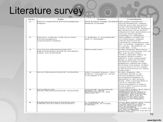
• [1]Atulkumarsingh, PrabhatRanjanTripathi, Microcontrolled Electromagnetic Engine, 2011, International
Conference on Advances in Electrical and Electronics Engineering (ICAEE'2011)
• [2]J.Rithula,J.Jeyashruthi and Y Anandhi,Electric Vehicle with Zero-fuel ElectromagneticAutomobile
Engine,2013,1,2&3Department of Electrical & Electronics Engineering, Sri Sairam Engineering College, West
Tambaram, Chennai, India. Volume 6, Number 4 (2013), pp. 483-486
• [3]Shirsendu Das,An ELECTROMAGNETIC MECHANISM WHICH WORKS LIKE AN ENGINE, IJETT- Volume 4
Issue 6-June 2013
• [4]Abil Joseph Eapen, AbyEshowVarughese, Arun T.P,Athul T.N, 2014,
ELECTROMAGNETIC ENGINE, International Journal of Research in Engineering and Technology.
• [5]AmarnathJayaprakash, Balaji, G., Bala Subramanian, S. and Naveen, N.,STUDIES ON ELECTROMAGNETIC
ENGINE International Journal of Development Research Vol. 4, Issue, 3, pp. 519-524, March, 2014
• [6]C. Sudhakar, K. Premkumar, K.Vijith, S.Balaji,“EMISSIONLESS ENGINE BY USING ELECTRO MAGNET”,
2014
• [7]K.Mahadevan and L.Balaveera Reddy “DESIGN DATA HAND BOOK” for Mechanical Engineers, Third
Edition.
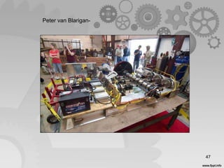
• [8]Peter van Blarigan, “ADVANCED INTERNAL COMBUSTION ENGINE RESEARCH ” Proceedings of the 2000
DOE Hydrogen Program Review.
48](https://image.slidesharecdn.com/ecmfinale-150617071145-lva1-app6892/85/ELECTROMAGNETIC-ENGINE-48-320.jpg)
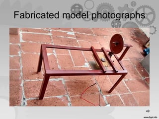
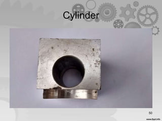
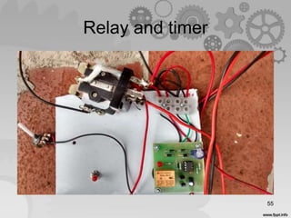
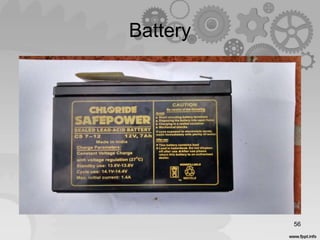
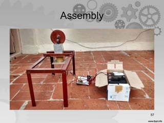
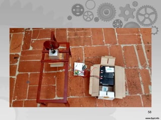


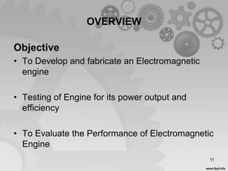
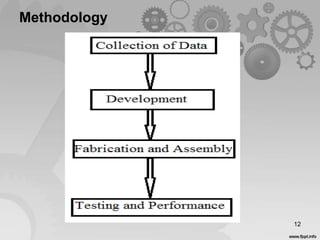
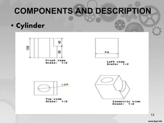
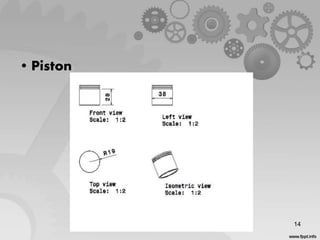
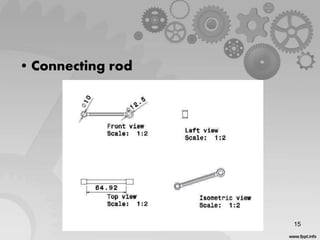
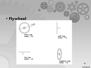
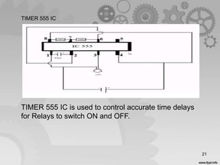
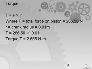
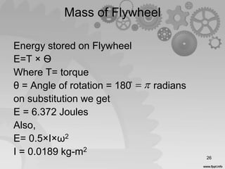
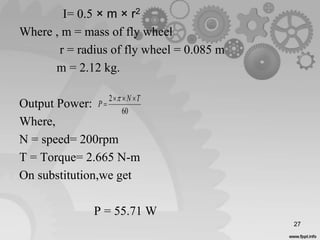
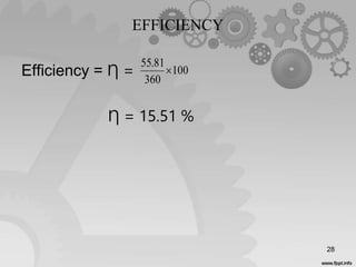
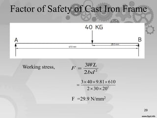
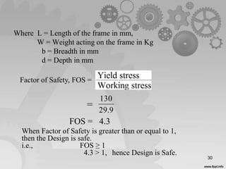
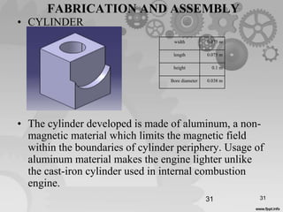
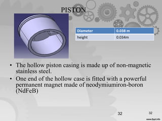
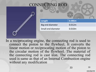
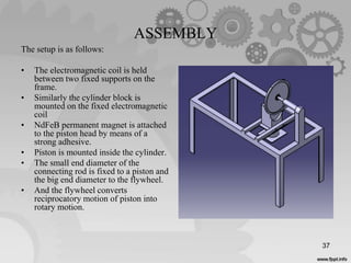
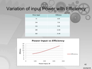
The document outlines a project proposal for the development and fabrication of an electromagnetic engine, detailing its objectives, components, design calculations, and testing results. It highlights the advantages of an electromagnetic engine over conventional internal combustion engines, including reduced pollution and the potential for enhanced efficiency through design modifications. The prototype demonstrated a maximum efficiency of 15.81% and an output power of 55.81 W, with recommendations for future improvements to increase its commercial viability.


