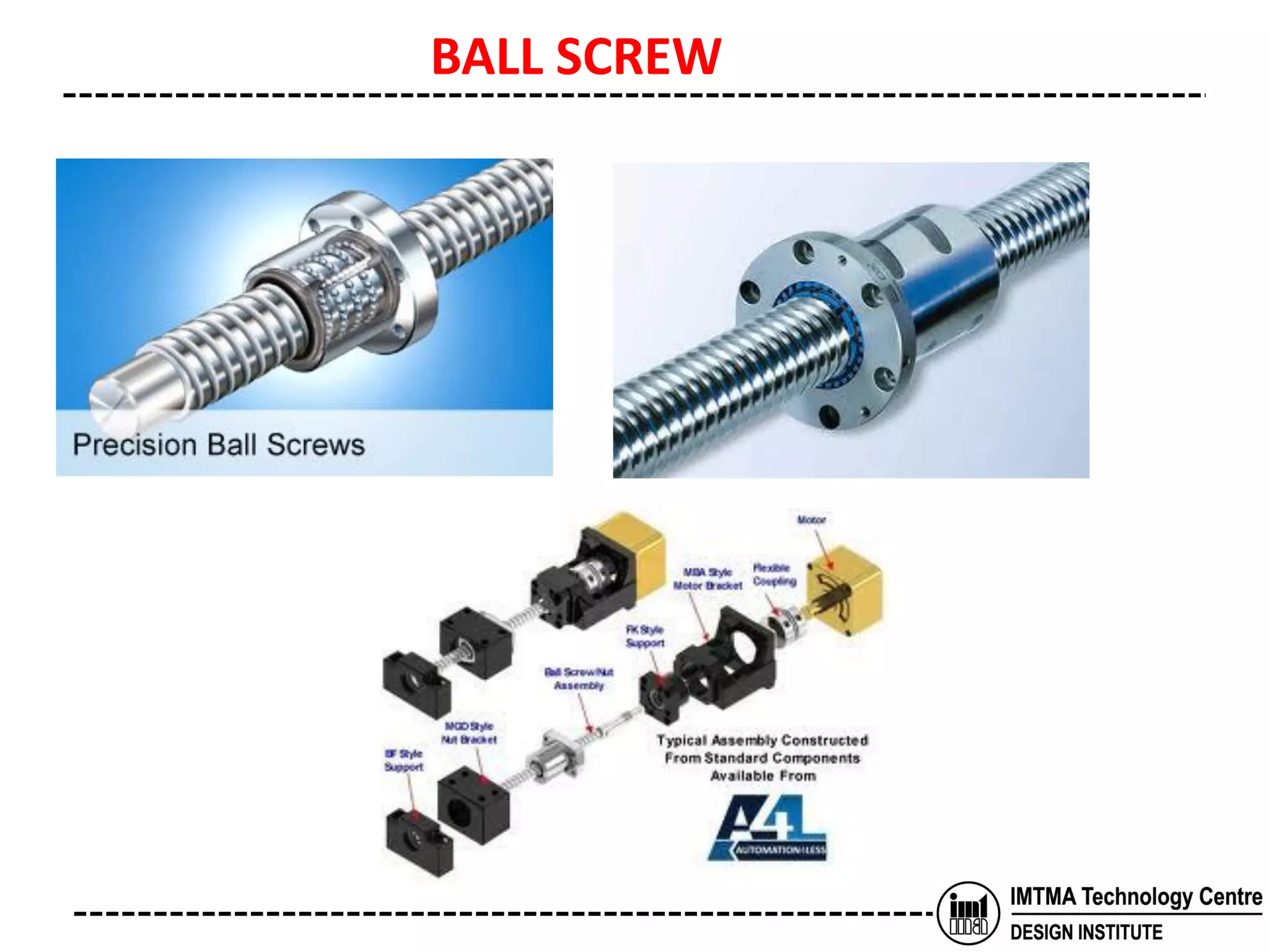
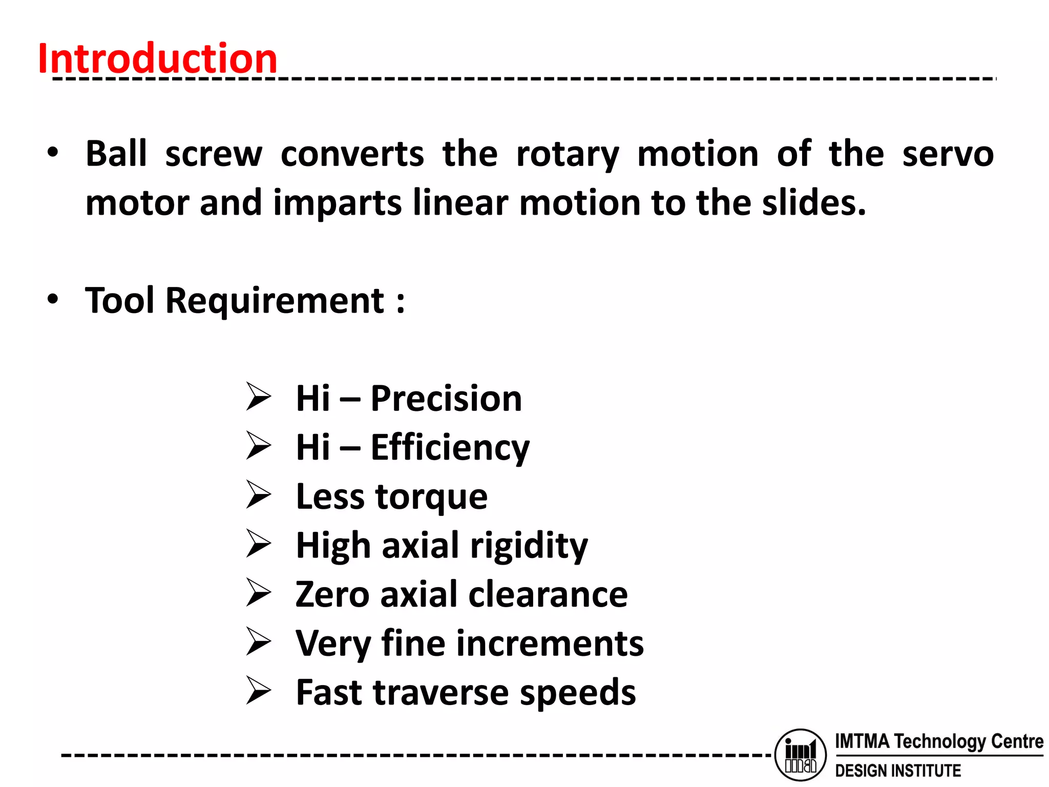
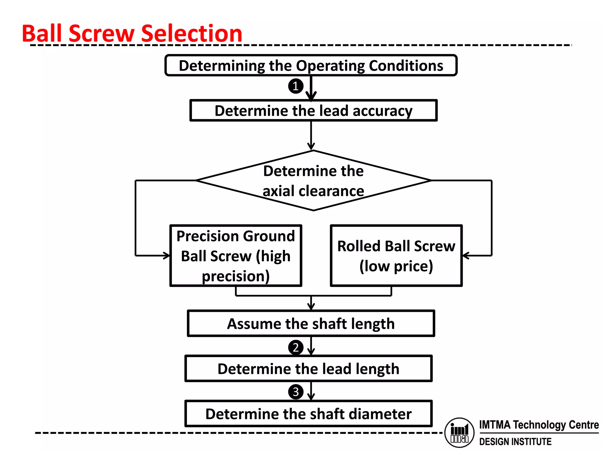
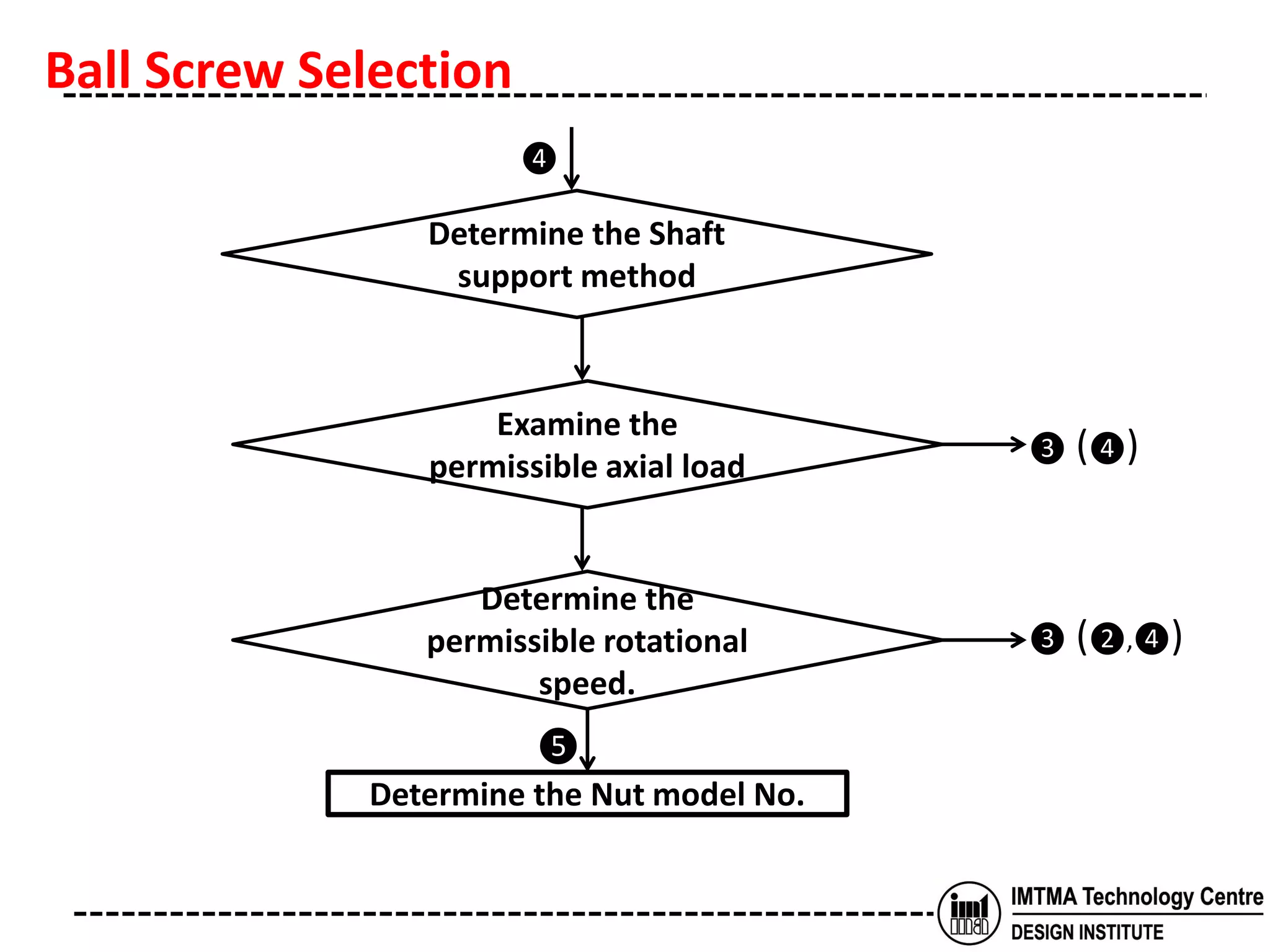
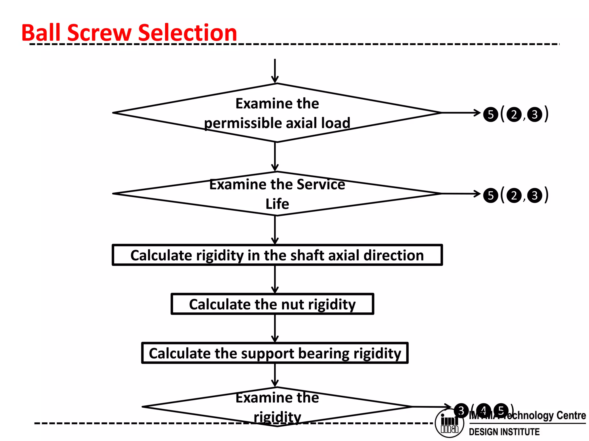
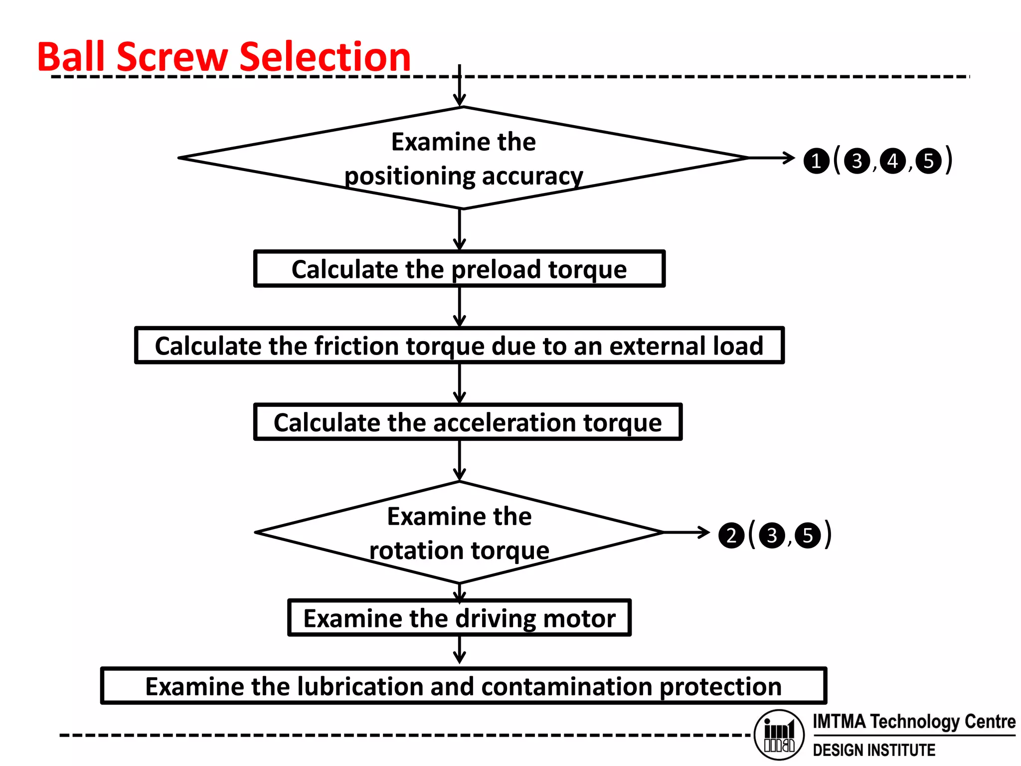
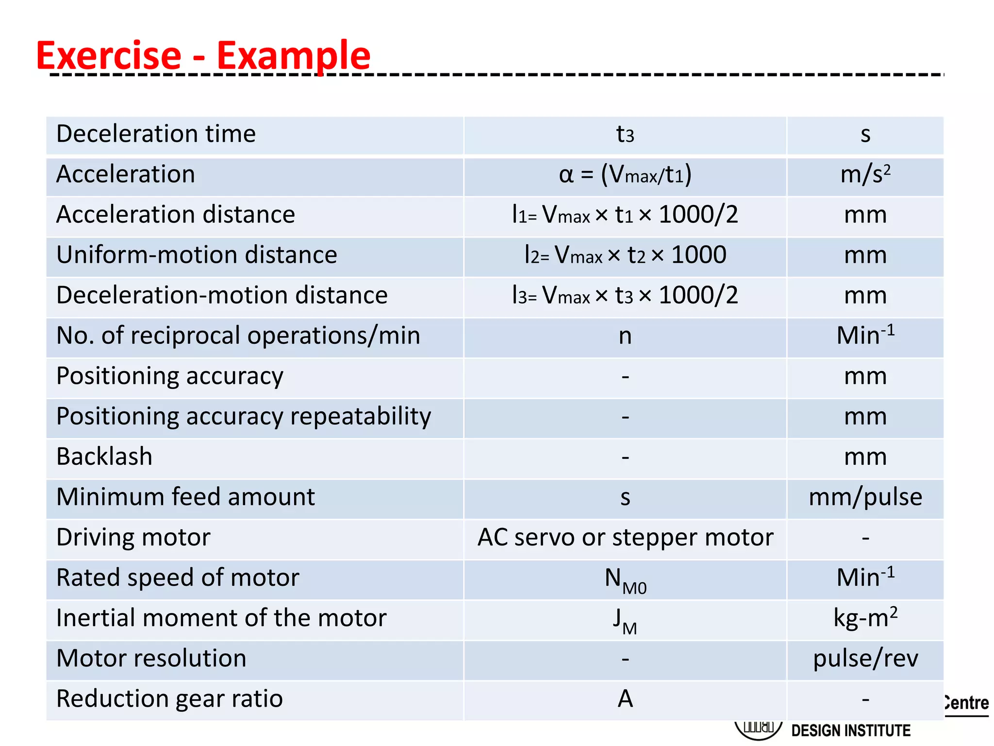
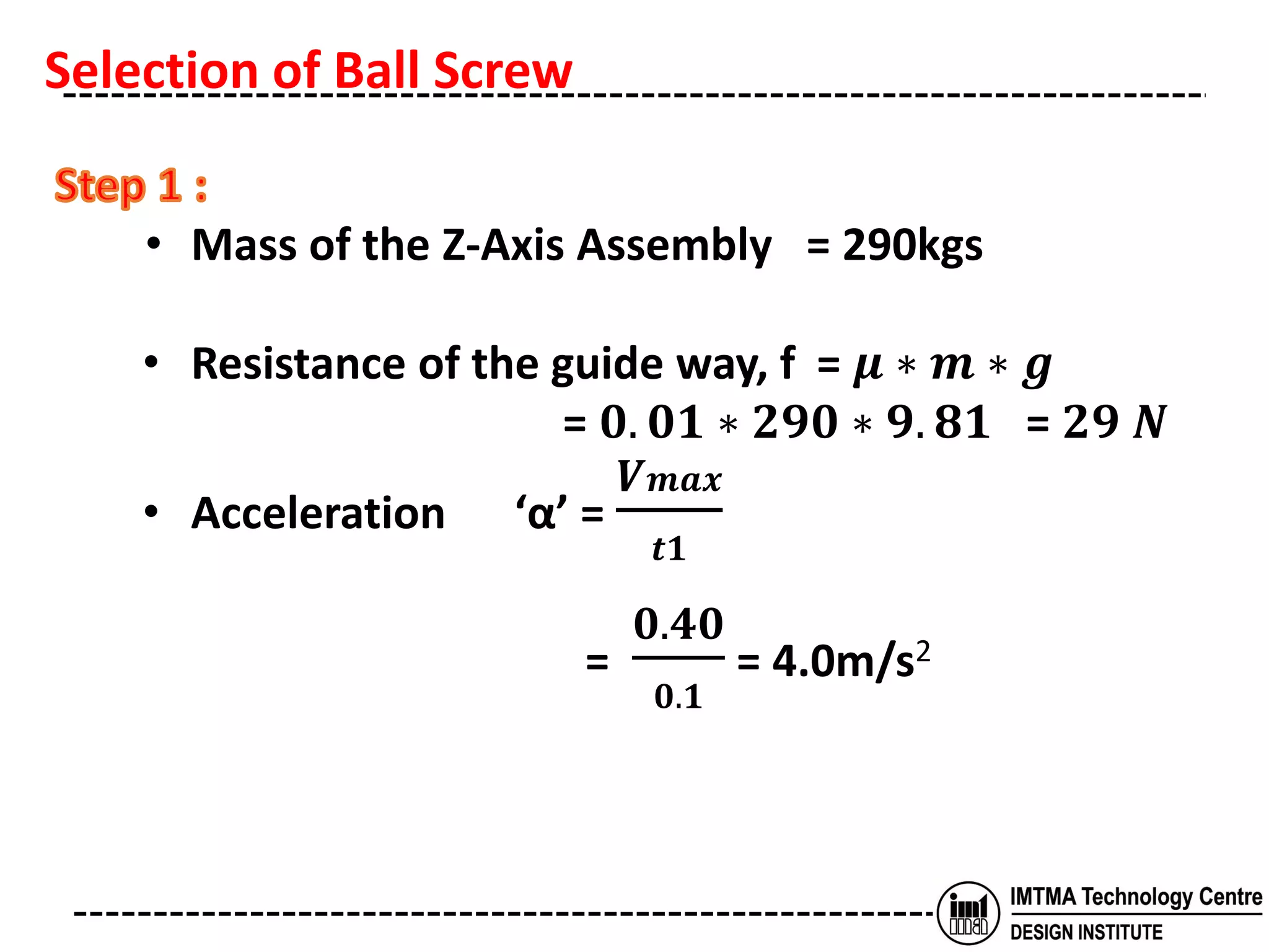
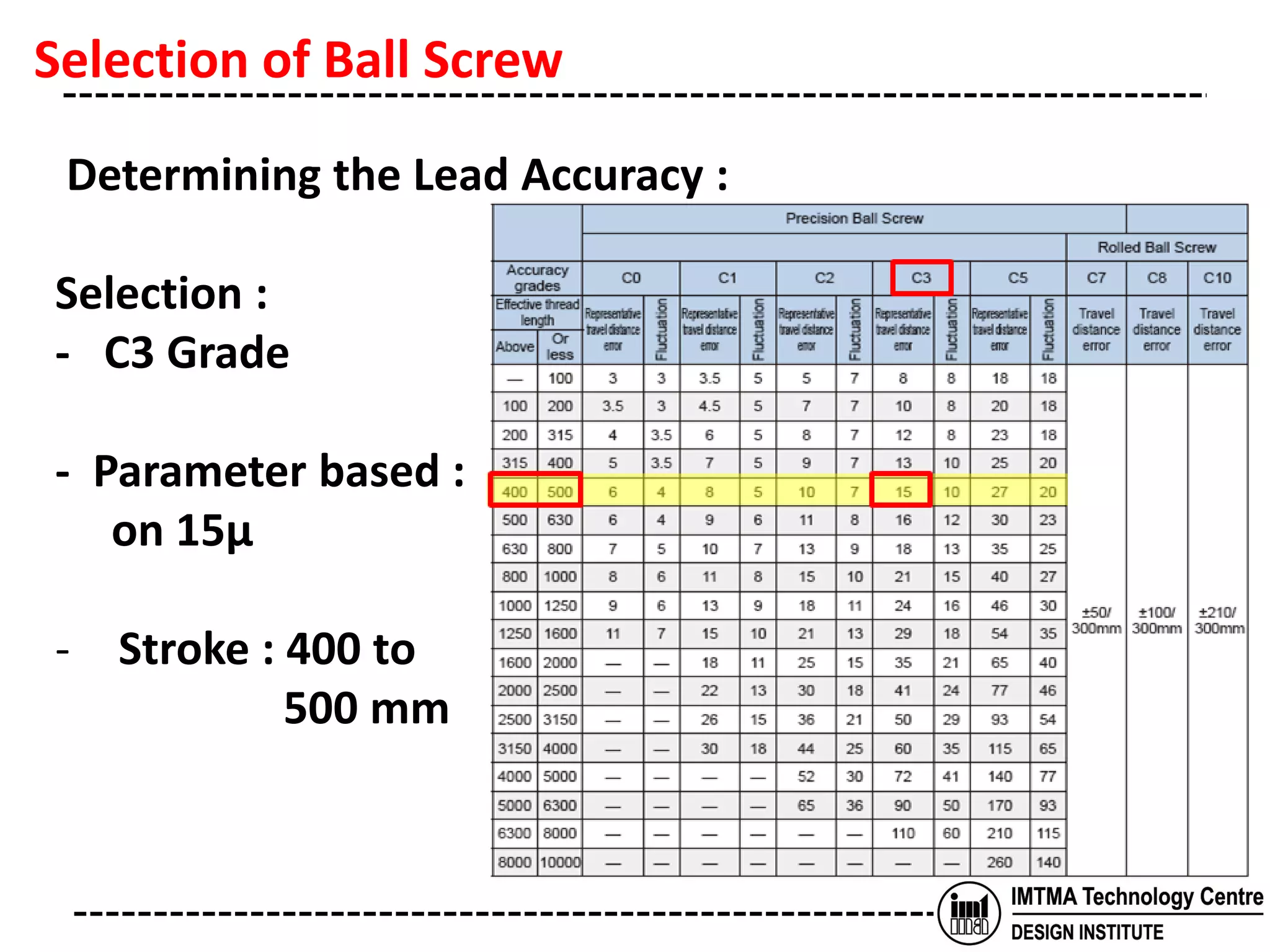
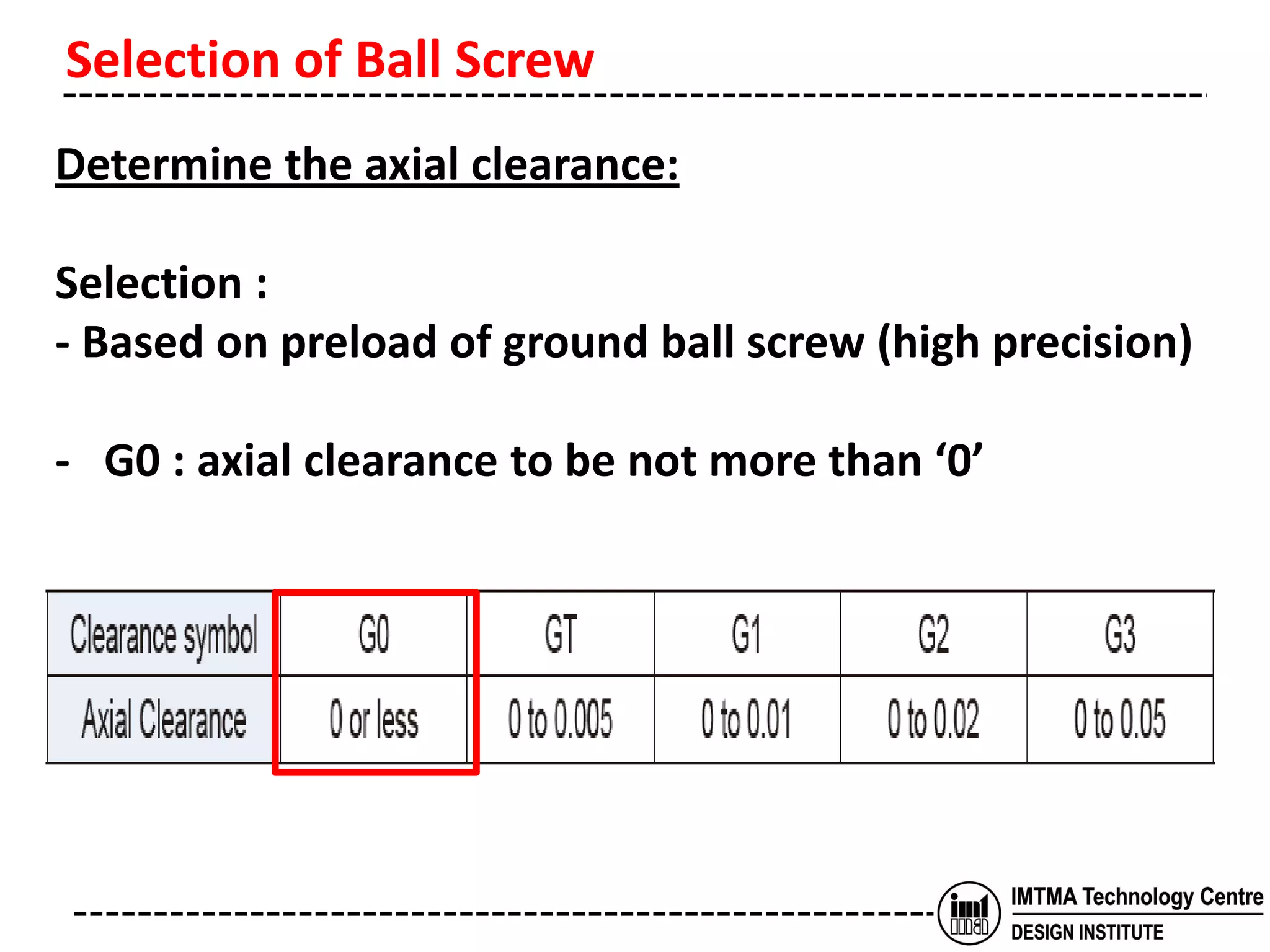
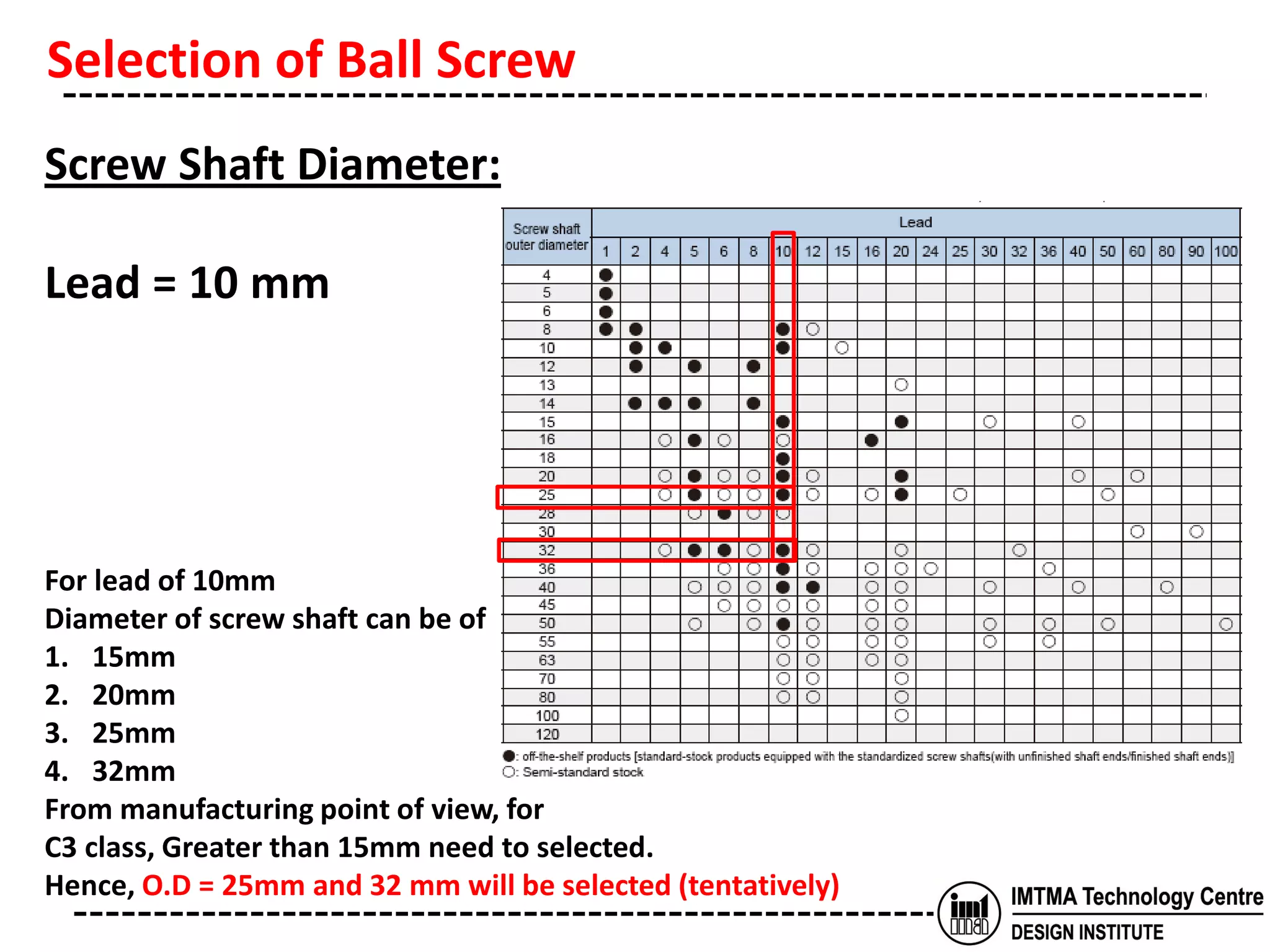
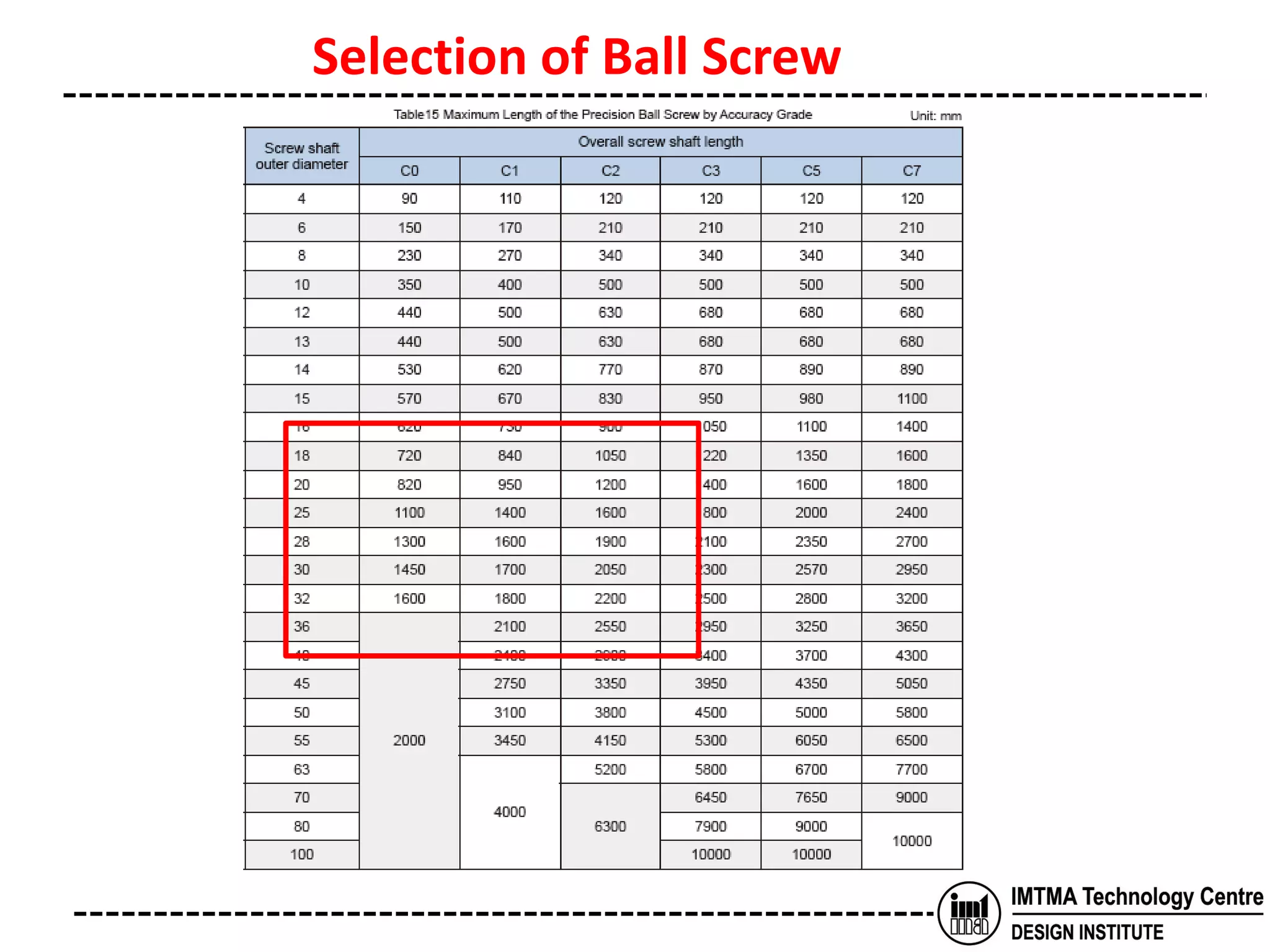
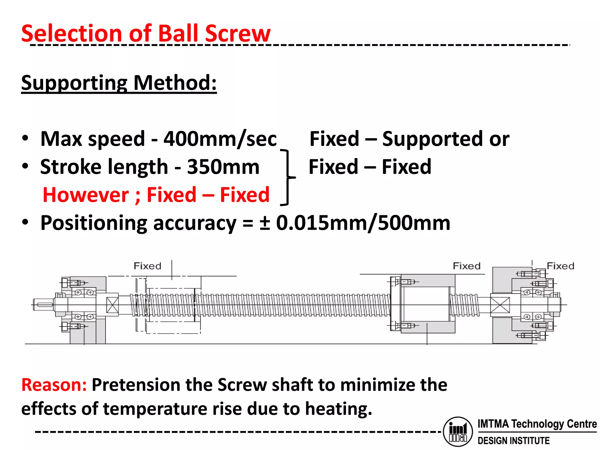
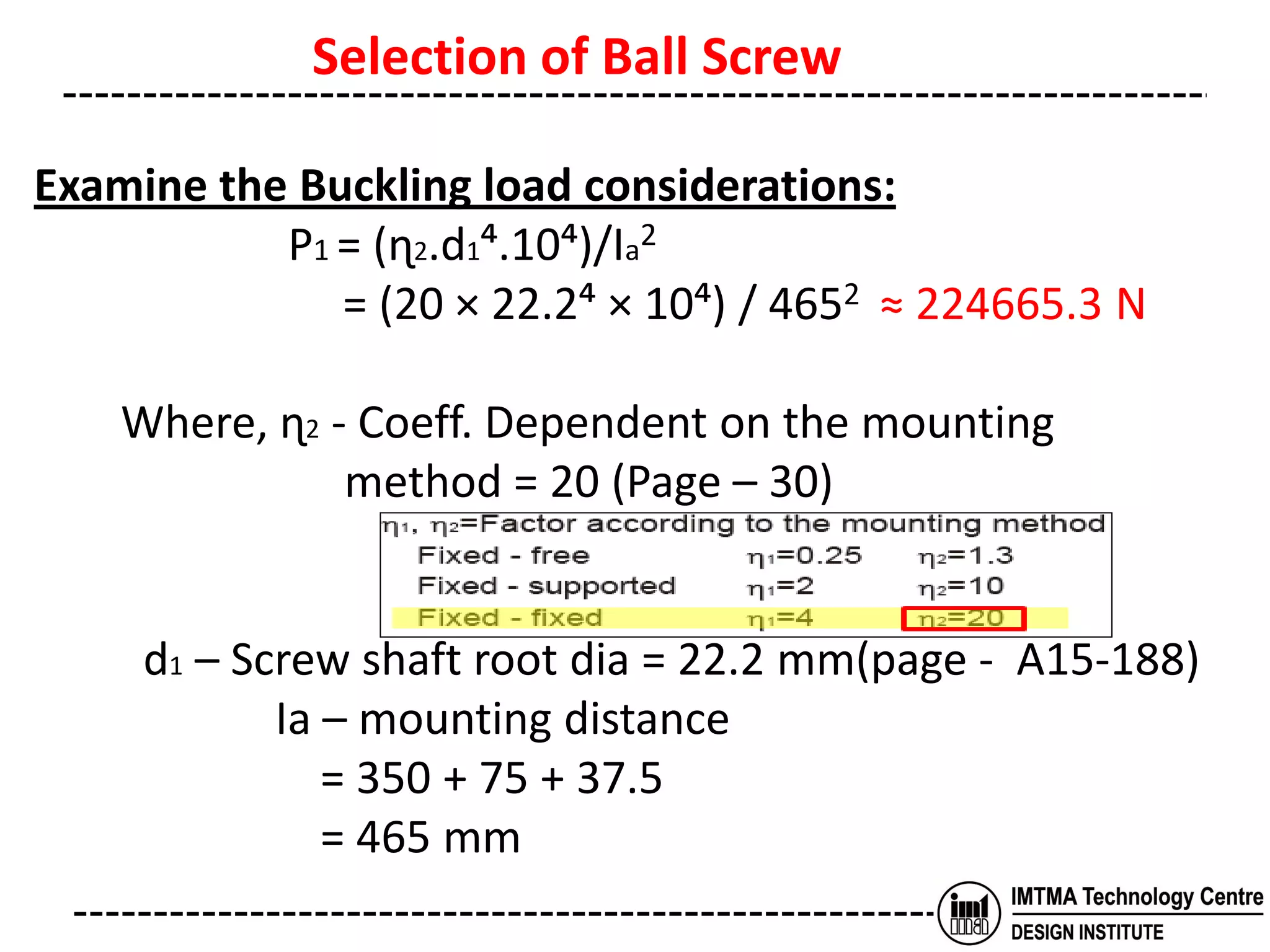
The document discusses the selection of a ball screw for a machine tool based on its operating conditions and design specifications. It outlines the steps to determine the key parameters for the ball screw like lead accuracy, axial clearance, screw length and diameter, support method, permissible axial load and rotational speed, nut model, rigidity, positioning accuracy, torques required, and motor specifications. An example selection process is provided based on the given design data and machine specifications for a lathe machine. Key factors like buckling load, tensile strength and critical speeds are examined to ensure safe design of the ball screw.
Design procedure for Cast iron pulley, Flat belt drive, V belt drive, Chain d...Dr.S.Thirumalvalavan
Title: UNIT-I; Design Procedure of Cast iron pulley, Flat belt drive, V belt drive, Chain drive & Wire ropes.
Subject Name: ME8651 - Design of Transmission Systems (DTS) B.E. Mechanical Engineering
Third Year, VI Semester
[Anna University R-2017]
Machine design, machine element, Belt drives and chain drives, selection of Belt - sheave and chain - sprocket, perancangan elemen mesin, transmisi sabuk dan rantai, pemilihan sabuk-puli dan rantai-sproket
Basics of Tube Bending explores the fundamentals of bending with a mandrel, bending tube with a plug mandrel, a ball mandrel and wiper die, and also explores and troubleshoots some of the most common tube bending problems and issues!
“V - Belts” - Design of Machine Element Umang Parmar
Introduction to V-Belts.
Construction of V-Belts.
Types of Standard Cross Section of V-Belts.
Designation of V-Belts.
Advantages of V-Belts & Limitation of V-Belts.
Application of V-Belts.
Method to calculate the press fit force for device as servo presses, hydraulic presses and other devices used to fit componets in automated assembly line
Design of Belt Drives With Pulley Theory By Prof. Sagar A. DhotareSagar Dhotare
It covers following points :-
Introduction flat and V Belt
Types of Belts
Calculations for Tensions
Maximum Torque Transmitted
pulley design
Advantage and disadvantages of V belt over flat belt
This project aim is to produce electricity using the concept of rotating wind turbine. Wind caused by moving train is used to generate electricity. The idea is to design wind turbine that can be installed between the slippers on the track. As a train passes by, wind pressure drives the turbine to generate the electricity, this device could be placed along railway line and make good use of waste resources. An electrical power generation system comprises of variable capacitors and power sources. Power sources is used in the form of generator to prime variable capacitor that effectively multiplies the priming energy of power source by extracting energy from passing vehicle
hello folks;
In this documentation, A 2 stage bevel reduction gearbox is designed.
The example taken is of the gearbox requirement for the Box-shipping conveyor. All the necessary design calculations for gears and shafts are carried out in a proper and easy-to-understand sequence. The material selection, standardized components (keys, oil seals likewise)selection from the design databook is also discussed with reasoning. As and when needed concepts are explained with the help of suitable graphs, visuals, and drawings.
This report is authorized by the team member's name mentioned on Slide.
Thank you!!
If you find it helpful do like&l share it with your engineering friends
The main objective of project is to understand the working of cone
type CVT which offers a continuum of gear ratios between the fixed
desired limits . It includes the analysis of
1) Design of CVT.
2) Fabrication of CVT model.
3) Performance analysis and testing
Vertical Screw Conveyor Design Project for MEX5277 - Machine Design
Step by step guide on how to create a Vertical Screw Conveyor.
Power calculation of a vertical screw conveyor.
SMD gearbox offers an industrial solution for motion transmission. as a trailblazer in the manufacturing of various types of industrial gearbox in Taiwan. SMD is one of the largest manufacturers and exporters of high precision gearbox solutions. SMD developed professional manufacturing capabilities offering various types of solutions such as inline planetary gearbox with flange-end, right angle gearbox, planetary gearbox with shaft-end, hollow rotary gearbox, and harmonic gearbox.
Visit us:- www.smdgearbox.com
Harnessing WebAssembly for Real-time Stateless Streaming PipelinesChristina Lin
Traditionally, dealing with real-time data pipelines has involved significant overhead, even for straightforward tasks like data transformation or masking. However, in this talk, we’ll venture into the dynamic realm of WebAssembly (WASM) and discover how it can revolutionize the creation of stateless streaming pipelines within a Kafka (Redpanda) broker. These pipelines are adept at managing low-latency, high-data-volume scenarios.
6th International Conference on Machine Learning & Applications (CMLA 2024)ClaraZara1
6th International Conference on Machine Learning & Applications (CMLA 2024) will provide an excellent international forum for sharing knowledge and results in theory, methodology and applications of on Machine Learning & Applications.
HEAP SORT ILLUSTRATED WITH HEAPIFY, BUILD HEAP FOR DYNAMIC ARRAYS.
Heap sort is a comparison-based sorting technique based on Binary Heap data structure. It is similar to the selection sort where we first find the minimum element and place the minimum element at the beginning. Repeat the same process for the remaining elements.
Understanding Inductive Bias in Machine LearningSUTEJAS
This presentation explores the concept of inductive bias in machine learning. It explains how algorithms come with built-in assumptions and preferences that guide the learning process. You'll learn about the different types of inductive bias and how they can impact the performance and generalizability of machine learning models.
The presentation also covers the positive and negative aspects of inductive bias, along with strategies for mitigating potential drawbacks. We'll explore examples of how bias manifests in algorithms like neural networks and decision trees.
By understanding inductive bias, you can gain valuable insights into how machine learning models work and make informed decisions when building and deploying them.
A review on techniques and modelling methodologies used for checking electrom...nooriasukmaningtyas
The proper function of the integrated circuit (IC) in an inhibiting electromagnetic environment has always been a serious concern throughout the decades of revolution in the world of electronics, from disjunct devices to today’s integrated circuit technology, where billions of transistors are combined on a single chip. The automotive industry and smart vehicles in particular, are confronting design issues such as being prone to electromagnetic interference (EMI). Electronic control devices calculate incorrect outputs because of EMI and sensors give misleading values which can prove fatal in case of automotives. In this paper, the authors have non exhaustively tried to review research work concerned with the investigation of EMI in ICs and prediction of this EMI using various modelling methodologies and measurement setups.
NO1 Uk best vashikaran specialist in delhi vashikaran baba near me online vas...Amil Baba Dawood bangali
Contact with Dawood Bhai Just call on +92322-6382012 and we'll help you. We'll solve all your problems within 12 to 24 hours and with 101% guarantee and with astrology systematic. If you want to take any personal or professional advice then also you can call us on +92322-6382012 , ONLINE LOVE PROBLEM & Other all types of Daily Life Problem's.Then CALL or WHATSAPP us on +92322-6382012 and Get all these problems solutions here by Amil Baba DAWOOD BANGALI
#vashikaranspecialist #astrologer #palmistry #amliyaat #taweez #manpasandshadi #horoscope #spiritual #lovelife #lovespell #marriagespell#aamilbabainpakistan #amilbabainkarachi #powerfullblackmagicspell #kalajadumantarspecialist #realamilbaba #AmilbabainPakistan #astrologerincanada #astrologerindubai #lovespellsmaster #kalajaduspecialist #lovespellsthatwork #aamilbabainlahore#blackmagicformarriage #aamilbaba #kalajadu #kalailam #taweez #wazifaexpert #jadumantar #vashikaranspecialist #astrologer #palmistry #amliyaat #taweez #manpasandshadi #horoscope #spiritual #lovelife #lovespell #marriagespell#aamilbabainpakistan #amilbabainkarachi #powerfullblackmagicspell #kalajadumantarspecialist #realamilbaba #AmilbabainPakistan #astrologerincanada #astrologerindubai #lovespellsmaster #kalajaduspecialist #lovespellsthatwork #aamilbabainlahore #blackmagicforlove #blackmagicformarriage #aamilbaba #kalajadu #kalailam #taweez #wazifaexpert #jadumantar #vashikaranspecialist #astrologer #palmistry #amliyaat #taweez #manpasandshadi #horoscope #spiritual #lovelife #lovespell #marriagespell#aamilbabainpakistan #amilbabainkarachi #powerfullblackmagicspell #kalajadumantarspecialist #realamilbaba #AmilbabainPakistan #astrologerincanada #astrologerindubai #lovespellsmaster #kalajaduspecialist #lovespellsthatwork #aamilbabainlahore #Amilbabainuk #amilbabainspain #amilbabaindubai #Amilbabainnorway #amilbabainkrachi #amilbabainlahore #amilbabaingujranwalan #amilbabainislamabad
Hierarchical Digital Twin of a Naval Power SystemKerry Sado
A hierarchical digital twin of a Naval DC power system has been developed and experimentally verified. Similar to other state-of-the-art digital twins, this technology creates a digital replica of the physical system executed in real-time or faster, which can modify hardware controls. However, its advantage stems from distributing computational efforts by utilizing a hierarchical structure composed of lower-level digital twin blocks and a higher-level system digital twin. Each digital twin block is associated with a physical subsystem of the hardware and communicates with a singular system digital twin, which creates a system-level response. By extracting information from each level of the hierarchy, power system controls of the hardware were reconfigured autonomously. This hierarchical digital twin development offers several advantages over other digital twins, particularly in the field of naval power systems. The hierarchical structure allows for greater computational efficiency and scalability while the ability to autonomously reconfigure hardware controls offers increased flexibility and responsiveness. The hierarchical decomposition and models utilized were well aligned with the physical twin, as indicated by the maximum deviations between the developed digital twin hierarchy and the hardware.
4. Ball Screw Mountings
• Precision angular contact bearings of class P3 is
employed to give high running accuracy.
• Bearings with 60° contact angle is used for high axial
load. (Ex: Metal removal)
• Fixed-Fixed arrangement for high speeds and pre-
stretched to compensate thermal expansion.
5. • The ball screw on the support end is free to expand if
temperature rise is beyond the pre-stretched limit,
hence buckling due to thermal effects is avoided.
• The ball screw and motor assembly are placed
centrally to guideways for minimizing the tilting
moment.
Ball Screw Mountings
6. • Ball screw converts the rotary motion of the servo
motor and imparts linear motion to the slides.
• Tool Requirement :
Hi – Precision
Hi – Efficiency
Less torque
High axial rigidity
Zero axial clearance
Very fine increments
Fast traverse speeds
Introduction
7. • Ball screw require 1/3 less torque compared to a
conventional sliding screw.
• Easy to convert rotary to linear and vice versa.
• Due to intricacies of the ball screw, its selection
should be very meticulous based on various
calculations.
Introduction
8. Ball Screw Selection
Determining the Operating Conditions
Determine the lead accuracy
❶
Determine the
axial clearance
Precision Ground
Ball Screw (high
precision)
Rolled Ball Screw
(low price)
Assume the shaft length
Determine the lead length
❷
Determine the shaft diameter
❸
9. Ball Screw Selection
Determine the Shaft
support method
❹
Examine the
permissible axial load
❸ (❹)
Determine the
permissible rotational
speed.
❸ (❷,❹)
Determine the Nut model No.
❺
10. Ball Screw Selection
Examine the
permissible axial load
❺(❷,❸)
Examine the Service
Life
❺(❷,❸)
Calculate rigidity in the shaft axial direction
Calculate the nut rigidity
Calculate the support bearing rigidity
Examine the
rigidity ❸(❹❺)
11. Ball Screw Selection
Examine the
positioning accuracy
❶(❸,❹,❺)
Calculate the preload torque
Calculate the friction torque due to an external load
Calculate the acceleration torque
Examine the
rotation torque
❷(❸,❺)
Examine the driving motor
Examine the lubrication and contamination protection
12. Exercise
• Determining the operating conditions:
PARAMETERS SYMBOL UNIT
Transfer orientation horizontal,
vertical,etc
-
Transferred mass m kg
Table guide method sliding, rolling
Frictional coefficient of the guide
surface
µ
Guide surface resistance f N
External load in the axial direction F N
Desired service life time Lh h
Stroke length ls mm
Operating speed Vmax m/s
Acceleration time t1 s
Uniform-motion time t2 s
13. Deceleration time t3 s
Acceleration α = (Vmax/t1) m/s2
Acceleration distance l1= Vmax × t1 × 1000/2 mm
Uniform-motion distance l2= Vmax × t2 × 1000 mm
Deceleration-motion distance l3= Vmax × t3 × 1000/2 mm
No. of reciprocal operations/min n Min-1
Positioning accuracy - mm
Positioning accuracy repeatability - mm
Backlash - mm
Minimum feed amount s mm/pulse
Driving motor AC servo or stepper motor -
Rated speed of motor NM0 Min-1
Inertial moment of the motor JM kg-m2
Motor resolution - pulse/rev
Reduction gear ratio A -
Exercise - Example
14. Machine specification
Swing over Saddle mm 350
Swing over Cross Slide mm 220
Chuck Size mm 165
Distance b/w Centres mm 380
Turning Diameter max. mm 165
Turning Length max. mm 350
Nose A2-5
Bore taper MT-4
Power kW 5.5
Maximum Speed rpm 4000
Speed range at constant power rpm 1000-3500
Spindle Bore mm 40
Standard Bar Capacity mm 26
Stroke X-Axis mm 130
Stroke Z-Axis mm 350
Feed rate mm/min 0-5000
Rapid Traverse Rate m/min 24
Bed slant angle deg 45
MACHINE SPECIFICATION
Machine Capacity
Spindle
Travels & Feedrates
15. Design Data
• Cutting speed Vc = 150m/min
• Maximum velocity Vmax = 24m/min
• Mass of the Z slide assembly m1 = 110kgs
• Mass of the X slide assembly m2 = 27kgs
• Mass of the turret assembly m3 = 42kgs
• Mass m4 = 104kgs
• Stroke Ls = 350mm
• Deceleration time t1 = 0.1 sec
• Acceleration time t2 =0.1 Sec
• Positioning accuracy 0.01/500mm
• Cutting force Px = 440N
• Axial force Pz = 1465N
• Guide resistance f = 29N
• Motor speed n =3000rpm
• Motor Torque Tm = 4.7Nm
• Guide way co-efficient of friction µ = 0.003
• Ratio i = 1:1 ( direct coupling )
• Minimum feed amount s = 0.001mm/p
16. • Mass of the Z-Axis Assembly = 290kgs
• Resistance of the guide way, f = 𝝁 ∗ 𝒎 ∗ 𝒈
= 𝟎. 𝟎𝟏 ∗ 𝟐𝟗𝟎 ∗ 𝟗. 𝟖𝟏 = 𝟐𝟗 𝑵
• Acceleration ‘α’ =
𝑽𝒎𝒂𝒙
𝒕𝟏
=
𝟎.𝟒𝟎
𝟎.𝟏
= 4.0m/s2
Selection of Ball Screw
17. Determining the Lead Accuracy :
Selection :
- C3 Grade
- Parameter based :
on 15µ
- Stroke : 400 to
500 mm
Selection of Ball Screw
18. Determine the axial clearance:
Selection :
- Based on preload of ground ball screw (high precision)
- G0 : axial clearance to be not more than ‘0’
Selection of Ball Screw
19. Determine the overall screw length:
- Overall length of nut (assumed) = 150mm
- End length(assumed) = 200mm
- Stroke length = 350mm
- Overall length of screw shaft = 150+200+350
= 700mm
Selection of Ball Screw
20. Determining the lead:
The rated motor speed of 3000 rpm and a specified
max speed of 400mm/sec requires a ball screw lead:
Lead min = 𝑴𝒂𝒙. 𝒍𝒊𝒏𝒆𝒂𝒓 𝒔𝒑𝒆𝒆𝒅
𝑹𝒂𝒕𝒆𝒅 𝒎𝒐𝒕𝒐𝒓 𝒔𝒑𝒆𝒆𝒅
= 400 × 60
3000
= 8 mm or greater
Select the lead : 10mm
Selection of Ball Screw
21. Encoder Selection:
The Ball Screw and motor are directly coupled without
using a reduction gear, the min resolution is derived
from the resolution of the encoder which is attached to
the AC Servo motor.
To meet the minimum feed of 0.001 mm/pulse the
encoder must generate:
=
𝟏𝟎
𝟎.𝟎𝟎𝟏
= 10000 PPR
Selection of Ball Screw
22. Screw Shaft Diameter:
Lead = 10 mm
For lead of 10mm
Diameter of screw shaft can be of
1. 15mm
2. 20mm
3. 25mm
4. 32mm
From manufacturing point of view, for
C3 class, Greater than 15mm need to selected.
Hence, O.D = 25mm and 32 mm will be selected (tentatively)
Selection of Ball Screw
24. Supporting Method:
• Max speed - 400mm/sec Fixed – Supported or
• Stroke length - 350mm Fixed – Fixed
However ; Fixed – Fixed
• Positioning accuracy = ± 0.015mm/500mm
Reason: Pretension the Screw shaft to minimize the
effects of temperature rise due to heating.
Selection of Ball Screw
25. Examine the permissible axial load:
• Axial load in accelerating motion (Fa1) :
Fa1 = f + µ.g.m + mα
= 29 + 0.01 × 290 × 9.81 + 290 × 4.0 = 1218 N
• Axial load in constant speed motion (Fa2) :
Fa2 = µ.m.g + f
= 0.01 × 290 × 9.81 + 29 = 57.5 N
• Axial load in decelerating motion (Fa3) :
Fa3 = µ.m.g + f –mα
= 0.01 × 290 × 9.81 + 29 – 290 × 4.0 = -1102.5 N
Selection of Ball Screw
26. Examine the permissible axial load:
• Axial load in light cutting operation(Fa4) :
Fa4 = Cutting force Px (turning) + Fa2
= 450 + 57.5 =1284 N ≈ 507 N
• Axial load in heavy cutting operation (Fa5) :
Fa5 = Cutting force Px(drilling thrust)+ Fa2
= 5400 + 57.5 = 14534 ≈ 5475.5 N
∴ The max axial load acting on Ball Screw
Famax = 5,475.5N
Selection of Ball Screw
27. Examine the Buckling load considerations:
P1 = (ɳ2.d1⁴.10⁴)/Ia2
= (20 × 22.2⁴ × 10⁴) / 4652 ≈ 224665.3 N
Where, ɳ2 - Coeff. Dependent on the mounting
method = 20 (Page – 30)
d1 – Screw shaft root dia = 22.2 mm(page - A15-188)
Ia – mounting distance
= 350 + 75 + 37.5
= 465 mm
Selection of Ball Screw
28. Examine the Buckling load considerations:
Where,d1 – Screw shaft root dia = 22.2 mm(page - A15-188)
Ia – mounting distance
= 350 + 75 + 37.5 = 465 mm
Selection of Ball Screw
29. Allowable Tensile & Compressive load:
P2 = (116.d21)
= (116 × 21.42) ≈ 53123.36 N
∴ P1 & P2 > Famax
Hence, Design is SAFE
Selection of Ball Screw
30. Determine the permissible rotational speed:
• Maximum rotational speed (Nmax) :
Nmax = Vmax / I
Where, I – Lead of screw shaft
= 400/10
= 40 rps
= 2400 rpm
• Critical speed of screw shaft (N1) :
N1 = (λ2.d1.10⁷)/ Ib
2
= (21.9 × 21.4 × 10⁷)/5652
= 14681.2 rpm
Selection of Ball Screw
32. Determine the permissible rotational speed(N2):
• DN Value N2 = 70000/D
Where, D – ball center to center diameter (page A-15 188)
N2 = 70000/26.3
= 2661.59 rpm
OR
Selection of Ball Screw
33. DN not greater than 70,000 (Condition)
DN = 26.3 × 2400
= 63,120
∴ N2 < Nmax & DN < 70,000
HENCE THE DESIGN IS SAFE
Selection of Ball Screw
34. Exercise
Drive motor: Specification/Requirements
Frictional torque due to external load:
T1 = Fa . l . A / (2.π.ɳ)
Where, Reduction gear ratio ‘A’ = 1
Fa = F + .µFv = 2244 + 0.15 × 180 × 9.81
PARAMETERS SYMBOL VALUE
Vertical load Fv 180
Coefficient of friction b/w guideways µ 0.15
Ball screw effiency ɳ 0.9
Cutting force
(drilling thrust for 0.12 mm feed)
F 2244
36. Exercise
Torque due to pre loading of ball screw (Td)
Td = (0.05 (tan β) ˉ0.5 . Fa0 .l. 10ˉ3) /(2.π)
Where,
tan β = lead/(π. Ball center to center diameter)
tan β = 10/(π × 33.75)
= 0.094
Fa0 (Preloading load) = 10% of Ca
= 0.1 × 34.8
= 3.45 kN
38. Exercise
Rotational speed (Nm) and Resolution (B):
Rotational speed (Nm):
Nm = V / (I.A)
= 15000 / (10 × 1)
= 1500 rpm
Resolution (B):
B = (I.A)/S
Where, S = Min Feed = 0.001mm
= (10 × 1) / 0.001
= 10,000 ppr
39. Exercise
Torque required for acceleration:
TA = J.ω
J = m. (I /(2. π )) 2 .10⁶ + Js + JM + Jc
Where, J – Moment of Inertia
Js – Screw shaft moment of Inertia
= 8.08 × 10ˉ3 kg.m2
For length of 750 mm = 6.06 × 10ˉ4 kg.m2
JM – Moment of inertia of motor = 0.0026 kg.m2
Jc – Moment of inertia of coupling
= 0.000664 kg.m2
M = 180 Kgs
41. Exercise
Moment of inertia (JM):
JM = J/C
Where, C = Coefficient depending on the motor and driver
= 5
= 4.32 × 10ˉ3 / 5
= 8.64 × 10ˉ4 kg.m2
∴ Moment of inertia of the motor should not be less than
8.64 × 10ˉ4 kg.m2
42. Exercise
Selected - 6/2000
• Rated rotational speed not less than 1500 rpm.
• Resolution obtained from the encoder and driver should
be 10,000 ppr.
• Instantaneous maximum torque not less than 6.78Nm.
• Rated torque not less than 5.35Nm.
• Moment of inertia of the motor not less than 8.64×10ˉ4
kg.m2.
44. Exercise
Calculation of rigidity:
Axial rigidity of Nut (KN) :
KN = (K .Fao/(0.1.Ca))⅓
Where, KN = K Since , Fao is 10% of Ca
KN = 870 kN/µm
Axial rigidity of Support Bearings (KB) :
KB = 0.655 kN/µm
(From bearing catalogue)
45. Exercise
Calculation of rigidity:
Axial rigidity of Total ball screw system (K) :
(1/K) = (1/ Ks) + (1/ KN) + (1/ KB)
= (1/0.727) + (1/0.87) + (1/0.655)
= 4.05166
K = 0.2468 kN/µm
Lost motion : Due to resistance of guideway
R = (2.Fa1) / K
=(2 × 0.54) / 0.2468
= 2.188µm
(Also depends on motor, coupling, drive elements)
46. Exercise
Thermal displacement due to heat:
3 °C Provided corresponding to Pre tension
+
3 °C Doubt
Δl = - (ƿ.t.l)
= (12 × 10-6 × 3 × 620)
= - 0.02232mm
Pre Tension: Fs = Δl. Ksl
Where, Ksl = Rigidity of thread screw b/w support bearing
= Ks/4
47. Exercise
Thermal displacement due to heat:
Pre Tension: Fs = Δl. Ksl
Where, Ksl = Rigidity of thread screw b/w support bearing
= Ks/4
= 0.727/4
= 0.1875 kN/µm
Fs = Δl. Ksl
= 22.32 × 0.18175
= 4.05 KN
48. Design verification
Ball screw diameter….………30mm
Lead…………………………….12mm
Stroke…………………………..300mm
Rapid speed…………………..30m/min
Acceleration time…t1………..0.15sec
Deceleration time…t2………0.15 sec
Maximum velocity…V……….0.5m/s
Mass of the table…m1…………340kgs
Mass of the work…m2………...150kgs
Motor speed and torque……..3000rpm / 7Nm
Motor inertial moment………..0.012kgm^2
Tangential force…Ft ………..142Kgf
Distance b/w ball screw support …715mm
Data based on standards
52. Design verification
Total torque during accln. T = T1+T2
= 6600+6320
= 12920Nmm
Motor torque rated = 7000Nmm
Motor torque peak = 18000Nmm
Hence, Motor torque peak > Total torque during acceleration
18000Nmm>12920Nmm
( Hence the design is safe)
Effective torque value = (Tk^2*t1)+(T1^2*t2)+(tg^2*t3)+(Ts^2*t4)
------------------------------------------------------
(t1+t2+t3+t4)
= 4872Nmm
Hence, Motor rated torque > Effective torque value
7000Nmm > 4872Nmm
( Hence the design is safe)